Johnson Controls 100 Series Installation Operation & Maintenance

Johnson Controls 100 Series Installation Operation & Maintenance

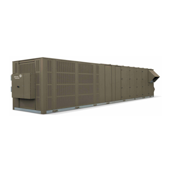
Single packaged unit sypal design level f with simplicity elite control
Hide thumbs Also See for 100 Series:
Table of Contents

Advertisement

Quick Links

PACKAGED ROOFTOP UNITS
Supersedes 100.50-NOM6 (316)
Form 100.50-NOM6 (817)
INSTALLATION, OPERATION, MAINTENANCE
035-21979-004
SERIES 100
SINGLE PACKAGED UNITS
YPAL DESIGN LEVEL F
WITH SIMPLICITY ELITE CONTROL
LD16707
50 THROUGH 65 TONS
Issue Date:
August 7, 2017

Advertisement

Table of Contents
loading
Need help?

Need help?

Do you have a question about the 100 Series and is the answer not in the manual?

Questions and answers

Summary of Contents for Johnson Controls 100 Series

  • Page 1 PACKAGED ROOFTOP UNITS Supersedes 100.50-NOM6 (316) Form 100.50-NOM6 (817) INSTALLATION, OPERATION, MAINTENANCE 035-21979-004 SERIES 100 SINGLE PACKAGED UNITS YPAL DESIGN LEVEL F WITH SIMPLICITY ELITE CONTROL LD16707 50 THROUGH 65 TONS Issue Date: August 7, 2017...
  • Page 2 All wiring must be in accor- dance with Johnson Controls’ published specifications and must be performed only by a qualified electrician. Johnson Controls will NOT be responsible for damage/problems resulting from improper connections to the controls or application of improper control signals.
  • Page 3 FORM 100.50-NOM6 ISSUE DATE: 8/07/2017 CHANGEABILITY OF THIS DOCUMENT In complying with Johnson Controls’ policy for con- regarding the applicability of these documents, rig- tinuous product improvement, the information con- ging, lifting, and operating/service personnel should tained in this document is subject to change without verify whether the equipment has been modified and notice.
  • Page 4 G :Staged Natural Gas Heat SS HX B :Bottom Supply M :Full Modulating Gas Heat L :Left Supply F :Full Modulating Gas Heat SS Staged HX R :Right Supply E :Electric Heat H :Hot Water Heat S :Steam Heat LD13270A JOHNSON CONTROLS...
  • Page 5 Single Point Power ..........................15 Dual Point Power ...........................15 Unit-Mounted Disconnect ........................16 Service And Installation ..........................16 Access Doors ............................16 Service Valves ............................16 Convenience Outlet ..........................16 Factory Run-Tested ..........................16 Gas Heat Sections ..........................16 Replaceable Core Filter Drier Option ....................16 JOHNSON CONTROLS...
  • Page 6: Table Of Contents

    Static Pressure Control Plastic Tubing ....................46 Duct Static Transducer ..........................46 Building Pressure Transducer ....................... 46 Static Pressure Probe Installation ......................46 Duct System ..............................48 Duct Connection Guidelines ........................48 Sound and Vibration Transmission ......................... 48 Gas Heating ..............................49 Gas Piping .............................49 JOHNSON CONTROLS...
  • Page 7 Fan Shaft Bearings ..........................62 Bearing Lock Devices ..........................63 Eccentric Type ............................63 Torquing of Set-screws .........................65 SECTION 5 – SEQUENCE OF OPERATION ......................67 Unit Type ................................ 67 Occupied / Unoccupied Mode ........................67 Constant Volume Mode (CV) .......................... 67 JOHNSON CONTROLS...
  • Page 8 Excessive SAT (Supply Air Temperature) Control ..................84 Cooling ..............................84 Heating ..............................85 Space Sensor With Setpoint Adjustment ......................86 Sequence of Operation .........................86 Space Sensor Fault Override Enable ......................86 Sequence of Operation .........................87 Remote Control .............................. 87 Sequence of Operation .........................87 JOHNSON CONTROLS...
  • Page 9 Alarm History ..............................99 SECTION 6 – USER INTERFACE ........................101 Interface Methods ............................101 Unit Controller Interface ..........................101 Program Button ............................101 Test/Up Button .............................. 102 Address / Down Button ..........................102 Alarm / Change ............................102 JOHNSON CONTROLS...
  • Page 10 Return Fan Pressure Transducer ......................152 Discharge Pressure Transducer ......................153 Suction Pressure Transducer ......................153 Humidity Sensors ..........................154 Sensor ............................154 Furnace Status Input ...........................154 Faults and Lockouts ............................. 159 Light Emitting Diode ..........................159 Alarm Codes ............................159 Alarm Troubleshooting ..........................161 JOHNSON CONTROLS...
  • Page 11 TABLE 42 - Furnace Status Input Staged Gas Heat .....................154 TABLE 43 - Humidity Sensor Outputs ........................154 TABLE 44 - Co Sensor Output ..........................155 TABLE 45 - Wiring Data ............................156 TABLE 46 - Alarm Code Descriptions ........................159 JOHNSON CONTROLS...
  • Page 12 FIGURE 29 - Eccentric Cam Locking Collar Bearing Installation ................64 FIGURE 30 - Split Bearing ............................65 FIGURE 31 - Condenser Fan VFD Potentiometer Settings ..................77 FIGURE 32 - Unit Controller Interface ........................101 FIGURE 33 - Connector Locations ........................155 JOHNSON CONTROLS...
  • Page 13: Figure 1 - Packaged Rooftop Air Conditioning Unit

    High-efficiency motors are standard. Motors are avail- occupied loads. The YORK YPAL system has 2 cir- able in ODP or TEFC construction. cuits in the unit. LD13271 FIGURE 1 - PACKAGED ROOFTOP AIR CONDITIONING UNIT JOHNSON CONTROLS...
  • Page 14 Allow for application of the YORK YPAL unit in HEATING SECTION sound-sensitive applications such as theaters and downtown areas. Contact Johnson Controls for more Staged Gas Heat details on site-specific requirements. The YORK YPAL rooftop gas furnace is an induced- draft gas furnace designed for high efficiency and reli- ability.
  • Page 15 This enables insulation from conditioned airstream. the unit to be operated in an emergency condition while minimizing power consumption. JOHNSON CONTROLS...
  • Page 16 Replaceable Core Filter Drier Option plify the service and repair task. Provides a means to remove moisture, dirt and debris from the refrigeration circuit in the event it is opened. JOHNSON CONTROLS...
  • Page 17: Section 2 - Installation

    750,000 BTU Input - 385-01866-002 ment must be commissioned and serviced 1,125,000 BTU Input - 385-01866-003 by an authorized Johnson Controls service mechanic or a qualified service person Not suitable for use with conventional venting systems. experienced in packaged rooftop instal- lation.
  • Page 18: Location

    In cases where space 6. Location of unit(s) should also be away from is limited, please call your local Johnson Controls rep- building flue stacks or exhaust ventilators to pre- resentative for additional information.
  • Page 19: Rigging And Handling

    Typical rigging using proper spreader bars and cables loads. Contact your Johnson Controls Sales Office if is shown in Figure 4 on page 19. See Figure 3 on you have any questions regarding unit weights.
  • Page 20: Unit Weights

    Supply Fan Motor - 15 HP Supply Fan Motor - 25 HP Supply Fan Motor - 30 HP Supply Fan Motor - 40 HP SUPPLY FAN VFD Supply Fan VFD - 5 - 10 HP Supply Fan VFD - 30 - 40 HP JOHNSON CONTROLS...
  • Page 21 Electric Heat - 150kW (Max) Electric Heat - 200kW (Max) Electric Heat - 250kW (Max) Gas Heat - 375 MBH (Max) Gas Heat - 750 MBH (Max) Gas Heat - 1125 MBH (Max) Hot Water Coil Steam Coil JOHNSON CONTROLS...
  • Page 22: Table 4 - Unit Center Of Gravity And Corner Loads

    BASIC UNIT W/ ECONO and HEATING (Hot Water Heat) 2347 2143 2491 2728 2346 2148 2502 2732 BASIC UNIT W/ ECONO and HEATING (Hot Water Heat) and 2673 2441 2509 2748 2672 2446 2519 2752 POWER EXHAUST (10HP motor, modulating damper, no VFD) JOHNSON CONTROLS...
  • Page 23 BASIC UNIT W/ ECONO and HEATING (Hot Water Heat) 2588 2378 2675 2911 2587 2383 2686 2915 BASIC UNIT W/ ECONO and HEATING (Hot Water Heat) and 2916 2679 2690 2929 2915 2684 2701 2933 POWER EXHAUST (10HP motor, modulating damper, no VFD) JOHNSON CONTROLS...
  • Page 24: Table 5 - Unit Corner Weights - 050-061 Models

    BASIC UNIT W/ ECONO and HEATING (Hot Water Heat) 2588 2378 2675 2911 2587 2383 2686 2915 BASIC UNIT W/ ECONO and HEATING (hot Water Heat) and POWER EXHAUST (10HP motor, modulating 2916 2679 2690 2929 2915 2684 2701 2933 damper, no VFD) JOHNSON CONTROLS...
  • Page 25: Unit Placement

    Johnson Controls will not be respon- sible for the unit fit up, leak integrity, or sound level Ground Level Locations with field fabricated roof curbs.
  • Page 26: Physical Data

    4 / 12 4 / 12 4 / 12 4 / 12 Size (Length x Width) (in.) 12X24 / 24X24 12X24 / 24X24 12X24 / 24X24 12X24 / 24X24 Total Filter Face Area (Square Feet) 61.6 61.6 61.6 JOHNSON CONTROLS...
  • Page 27: Table 7 - Physical Data - Compressors

    ZP137 ZP137 ZP137 13.58 13.58 13.58 13.58 25.0 50.0 75.0 100.0 MODEL 060 ZP182 ZP137 ZP182 ZP137 17.95 13.30 17.95 13.30 28.7 57.4 78.7 100.0 061 ZP182 ZP137 ZP182 ZP154 17.95 13.30 17.60 14.86 28.2 55.8 76.7 100.0 JOHNSON CONTROLS...
  • Page 28: Figure 4 - Location And Dimension Drawing / 050-061 Models, Bottom Supply / Bottom Return

    FORM 100.50-NOM6 SECTION 2 – INSTALLATION ISSUE DATE: 8/07/2017 LD08295B FIGURE 4 - LOCATION AND DIMENSION DRAWING / 050-061 MODELS, BOTTOM SUPPLY / BOTTOM RETURN, STANDARD CABINET JOHNSON CONTROLS...
  • Page 29: Figure 5 - Location And Dimension Drawing / 050-061 Models, Bottom Supply / Side Return

    FORM 100.50-NOM6 SECTION 2 – INSTALLATION ISSUE DATE: 8/07/2017 LD08370A FIGURE 5 - LOCATION AND DIMENSION DRAWING / 050-061 MODELS, BOTTOM SUPPLY / SIDE RETURN, STANDARD CABINET JOHNSON CONTROLS...
  • Page 30: Figure 6 - Location And Dimension Drawing / 050-061 Models, Side Supply / Rear Return

    FORM 100.50-NOM6 SECTION 2 – INSTALLATION ISSUE DATE: 8/07/2017 LD08296A FIGURE 6 - LOCATION AND DIMENSION DRAWING / 050-061 MODELS, SIDE SUPPLY / REAR RETURN, STANDARD CABINET JOHNSON CONTROLS...
  • Page 31: Figure 7 - Location And Dimension Drawing, / 050-061 Models, Bottom Supply / Bottom Return

    FORM 100.50-NOM6 SECTION 2 – INSTALLATION ISSUE DATE: 8/07/2017 LD14761 FIGURE 7 - LOCATION AND DIMENSION DRAWING, / 050-061 MODELS, BOTTOM SUPPLY / BOTTOM RETURN, EXTENDED CABINET JOHNSON CONTROLS...
  • Page 32: Figure 8 - Location And Dimension Drawing / 050-061 Models, Bottom Supply / Side Return

    FORM 100.50-NOM6 SECTION 2 – INSTALLATION ISSUE DATE: 8/07/2017 63.25 LD14762 FIGURE 8 - LOCATION AND DIMENSION DRAWING / 050-061 MODELS, BOTTOM SUPPLY / SIDE RETURN, EXTENDED CABINET JOHNSON CONTROLS...
  • Page 33: Figure 9 - Location And Dimension Drawing / 050-061 Models, Side Supply / Rear Return, Extended Cabinet

    FORM 100.50-NOM6 SECTION 2 – INSTALLATION ISSUE DATE: 8/07/2017 LD14763 FIGURE 9 - LOCATION AND DIMENSION DRAWING / 050-061 MODELS, SIDE SUPPLY / REAR RETURN, EXTENDED CABINET JOHNSON CONTROLS...
  • Page 34: Figure 10 - Curb Layout Drawing / 050-061 Models, Standard And Extended Cabinet

    2. Curb configuration for “bottom” return and “bottom” supply. 3. These drawings are not intended as construction documents for the field fabricated roof curbs. Johnson Controls will not be responsible for the unit fit up, leak integrity, or sound level for installation using field fabricated roof curbs.
  • Page 35: Electrical Data

    18.6 14.7 ZP182 55.7 26.9 23.7 ZP154 51.3 22.4 19.8 ZP182 55.7 25.0 23.7 ZP137 48.0 18.6 14.7 ZP182 55.7 25.0 23.7 TABLE 9 - POWER SUPPLY VOLTAGE LIMITS POWER SUPPLY MINIMUM VOLTAGE MAXIMUM VOLTAGE 208/230V/3Ph/60Hz 460V/3Ph/60Hz 575V/3Ph/60Hz JOHNSON CONTROLS...
  • Page 36: Table 10 - Supply And Exhaust Fan Motor Data - Odp

    208V/3PH/60HZ 230V/3PH/60HZ 460V/3PH/60HZ 575V/3PH/60HZ FANS 50-61 TONS 32.4 27.6 13.6 12.0 TABLE 14 - MISCELLANEOUS ELECTRICAL DATA NOMINAL VOLTAGE DESCRIPTION 208 / 230V 460V 575V 380V-60 AMPS AMPS AMPS AMPS CONTROL TRANSFORMER 500 VA CONVENIENCE OUTLET GAS HEAT JOHNSON CONTROLS...
  • Page 37: Filters

    6 on page 26. The unit should never be operated for DRAIN PAN any length of time without the proper filters installed NO. 3 - FAN RUNNING AND CONDENSATE in the unit. LD13269 FIGURE 11 - DRAIN TRAP SHOWING WATER LOCATION DURING DRAW THROUGH OPERATION STAGES JOHNSON CONTROLS...
  • Page 38: Condensate Drain

    W2, and W3. The four thermostat cooling inputs con- nect to the P2 and P3 terminal block on the Simplicity The trap and drain lines should be protected from control board to terminals Y1, Y2, Y3, and Y4. freezing. Plumbing must conform to local codes. Use JOHNSON CONTROLS...
  • Page 39: Fan Input

    • On VAV units set the supply fan output to 100% supply an external power supply for the sensor. This is in addition to the two wires connect to the unit. The • Turn the power exhaust fan ON JOHNSON CONTROLS...
  • Page 40: Bas Economizer Input

    • At 2.0VDC – the control uses the lower setpoint • Between 2.0 VDC and 10VDC the change in setpoint is proportional to the change in voltage. • At 10.0VDC – the control uses the upper setpoint JOHNSON CONTROLS...
  • Page 41: Figure 13 - Wiring Connections

    1. Wiring shown indicates typical wiring. Refer to the IOM manual for more detailed wiring methods and options. 2. All wiring is Class 2, low voltage. 3. Maximum power available from the 24 VAC terminal is 40 VA. 4. Use shielded wire where shown. FIGURE 13 - WIRING CONNECTIONS JOHNSON CONTROLS...
  • Page 42: Electrical Service Sizing

    100% of the rated load amps for all other loads includ- ed in the circuit, per N.E.C. Article 440-34. The minimum recommended disconnect switch is based on 115% of the rated load amps for all loads in- cluded in the circuit, per N.E.C. JOHNSON CONTROLS...
  • Page 43: Figure 14 - Single-Point Power Supply Wiring

    3. Minimum Circuit Ampacity (MCA) is based on U.L. Standard 1995, Section 36.14 (N.E.C. Section 440-34). 4. Maximum Dual Element Fuse size is based on U.L. Standard 1995, Section 36.15 (N.E.C. Section 440-22). 5. Use copper conductors only. FIGURE 14 - SINGLE-POINT POWER SUPPLY WIRING JOHNSON CONTROLS...
  • Page 44: Figure 15 - Single-Point Power Supply Wiring With Non-Fused Disconnect

    100, and is intended for isolating the unit from the available power supply to perform maintenance and troubleshooting. This disconnect switch is not intended to be a Load Break Device. FIGURE 15 - SINGLE-POINT POWER SUPPLY WIRING WITH NON-FUSED DISCONNECT JOHNSON CONTROLS...
  • Page 45: Figure 16 - Dual-Point Power Supply Wiring

    3. Minimum Circuit Ampacity (MCA) is based on U.L. Standard 1995, Section 36.14 (N.E.C. Section 440.34). 4. Maximum Dual Element Fuse size is based on U.L. Standard 1995, Section 36.15 (N.E.C. Section 440.22). 5. Use copper conductors only. FIGURE 16 - DUAL-POINT POWER SUPPLY WIRING JOHNSON CONTROLS...
  • Page 46: Controls

    The tap should never be placed above the ceiling. JOHNSON CONTROLS...
  • Page 47: Figure 17 - Atmospheric Sensor Probe

    Filter Compartment Compartment Economizer Economizer Compartment Compartment LD13127 The atmospheric probe should be mounted on the support post on the control side of the unit between the Economizer and the Filter compartment. FIGURE 17 - ATMOSPHERIC SENSOR PROBE JOHNSON CONTROLS...
  • Page 48: Duct System

    This diagram is provided as a visual reference of the York YPAL discharge and return air openings and locations for all sizes. Please refer to Figures 5 through 10 for exact size and location of panels and openings. FIGURE 18 - DISCHARGE AND RETURN AIR OPENINGS JOHNSON CONTROLS...
  • Page 49: Gas Heating

    Many local terial suitable for the purpose. NEVER USE A codes require that a shut off valve be located external FLAME! JOHNSON CONTROLS...
  • Page 50: Combustion Vent

    2. LD11766 4. See Figure 20 on page 50 for the proper ori- FIGURE 20 - COMBUSTION VENT entation of the combustion vent. The internal baffle(s) must direct the flue gases upward. JOHNSON CONTROLS...
  • Page 51: Section 3 - Start-Up

    To protect warranty, this equipment must CHECKING THE SYSTEM PRIOR TO INITIAL be installed and serviced by an authorized START (NO POWER) Johnson Controls service mechanic or a Unit Checks qualified service person experienced in air handling and condenser unit instal- 1.
  • Page 52: Unit Checks - Power Applied

    4. Insure proper compressor rotation - see following instruction on Verifying Compressor Rotation. Fan Hold Down EXHAUST FAN ASSEMBLY Brackets (4) Fan Hold Down Brackets (4) LD13268 SUPPLY FAN ASSEMBLY FIGURE 21 - FAN HOLD DOWN BRACKETS JOHNSON CONTROLS...
  • Page 53: Verifying Compressor Rotation

    Table 21 on page 53 from the discharge pressure to determine the equivalent saturation tem- perature. JOHNSON CONTROLS...
  • Page 54: Superheat (R-410A)

    Pressure as shown in Table 22 on page 55. capable of sensing refrigerant R-410A. If the unit is functioning satisfactorily during the initial operating period, no safeties trip and the unit controls are functioning properly, the rooftop unit is ready to be placed into operation. JOHNSON CONTROLS...
  • Page 55: Table 22 - R410-A Pressure / Temperature Chart

    FORM 100.50-NOM6 SECTION 3 – START-UP ISSUE DATE: 8/07/2017 TABLE 22 - R410-A PRESSURE / TEMPERATURE CHART PSIG TEMP °F PSIG TEMP °F JOHNSON CONTROLS...
  • Page 56: Gas Heat Models

    NATURAL 4.5 “WC 13.5 “WC 1.2 “WC 3.5 “WC valve. On staged gas heat, as soon as the limit closes PROPANE 11.0 “WC 13.5 “WC 4.2 “WC 10.0”WC the ignition control will reinitiate the ignition sequence. JOHNSON CONTROLS...
  • Page 57: Manifold Gas Pressure Adjustment

    23 on page 56. TABLE 24 - GAS HEAT PERFORMANCE DATA AIRFLOW GAS INPUT CAPACITY MAXIMUM OUTPUT CAPACITY TEMP. RISE UNIT (BTU/HR X 1000) (BTU/HR X 1000) (°F) MIN. MAX. 7,500 24,000 50-61 14,000 24,000 1125 21,000 24,000 JOHNSON CONTROLS...
  • Page 58 FORM 100.50-NOM6 SECTION 3 – START-UP ISSUE DATE: 8/07/2017 THIS PAGE INTENTIONALLY LEFT BLANK. JOHNSON CONTROLS...
  • Page 59: Section 4 - Maintenance

    If a system failure compressor. occurs due to improper maintenance during the warran- ty period, Johnson Controls will not be liable for costs Fan Bearing Lubrication incurred to return the unit to satisfactory operation.
  • Page 60: Periodic Maintenance - Three To Six Months

    A belt ten- for proper operation. sioned too tightly can overload the motor electrical, causing nuisance tripping of the motor overloads and/ or motor failure and/or shaft failure. JOHNSON CONTROLS...
  • Page 61: Belt Replacement

    A Browning Belt tension gauge is used in Figure 25 on page 61 to properly tension belts. LD06355 LD06354 FIGURE 26 - EXAMPLE OF FC FAN SHAFT/WHEEL FIGURE 25 - BELT TENSIONING GAUGE MARKING JOHNSON CONTROLS...
  • Page 62: Forward Curved Fans

    If necessary, use a brass bar or pipe against the inner race to drift bearing into 11. Torque all hardware. JOHNSON CONTROLS...
  • Page 63: Bearing Lock Devices

    If an adapter or grease fitting of improper size and length is used, the locking pin may be either too tight or loose and can affect the alignment and re-lubrication of the bearing. JOHNSON CONTROLS...
  • Page 64: Table 26 - Set Screw Torque

    228 - 296 19.0 - 24.7 7/16 7/32 348 - 452 29.0 - 37.7 1/2 1/4 504 - 655 42.0 - 54.6 LD06358 5/8 5/16 1104 - 1435 92.0 - 119.6 FIGURE 29 - ECCENTRIC CAM LOCKING COLLAR BEARING INSTALLATION JOHNSON CONTROLS...
  • Page 65: Torquing Of Set-Screws

    It is extremely important to ensure that proper radial clearances are observed between the roller bearings and outer face. Failure to make proper adjustments will cause prema- ture failure of the bearing. 00536vip Seal FIGURE 30 - SPLIT BEARING JOHNSON CONTROLS...
  • Page 66 FORM 100.50-NOM6 SECTION 4 – MAINTENANCE ISSUE DATE: 8/07/2017 THIS PAGE INTENTIONALLY LEFT BLANK. JOHNSON CONTROLS...
  • Page 67: Section 5 - Sequence Of Operation

    SYSTEMS OPTIONS tab in the Simplicity PC • “COOLING MODE OPERATION ENABLED” software package. – must be enabled using Parameter 53 under the PROGRAM key on the Simplicity control board or under the COOLING SETUP tab in the Sim- plicity PC software package. JOHNSON CONTROLS...
  • Page 68: Thermostat Input

    A programmable thermostat would be required in order • Y1 – First Stage of Cooling – 1st compressor from to change the heating temperature settings between oc- System 1. cupied and unoccupied. • Y2 – Second Stage of Cooling – 2nd compressor from System 1. JOHNSON CONTROLS...
  • Page 69: Space Sensor - Hard Wired Or Communicated

    COOLING SETUP tab of the in the – If the space temperature is greater than 2.0° F Simplicity PC software package. or more above the “CV OCCUPIED COOLING SETPOINT” or “CV UNOCCUPIED COOLING SETPOINT” the control will bring on the first JOHNSON CONTROLS...
  • Page 70: Stand Alone

    • If after 3 or 5 minutes the return air temperature is • “CV OCCUPIED HEATING SETPOINT” – using between 1.5° F and 1.9° F above the “CV OCCU- Parameter 11 under the PROGRAM key on the JOHNSON CONTROLS...
  • Page 71: Variable Air Volume (Vav)

    “CV OCCUPIED HEATING” or “CV PROGRAM key on the Simplicity control board UNOCCUPIED HEATING SETPOINT” the con- or under the COOLING SETUP tab in the Sim- trol energizes the first stage of heat. plicity PC software package. JOHNSON CONTROLS...
  • Page 72: Cooling - Unoccupied With Thermostat

    • “VAV COOLING SUPPLY AIR TEMP UPPER SAT SETPOINT” or “VAV COOLING SUPPLY SETPOINT” – using Parameter 23 under the AIR TEMP LOWER SETPOINT”. If turning a PROGRAM key on the Simplicity control board compressor ON would result in the specified drop JOHNSON CONTROLS...
  • Page 73: Cooling - Unoccupied With A Hard Wired Or Communicated Space Sensor

    Simplicity control board or under the HEAT- The supply air temperature is still 5.0° F or ING SETUP tab in the Simplicity PC software more, greater than the “VAV UPPER COOLING package. SAT SETPOINT” or “VAV LOWER COOLING SAT SETPOINT”. JOHNSON CONTROLS...
  • Page 74: Heating - Unoccupied With A Hard Wired Or Communicated Space Sensor

    ON. the Simplicity PC software package. • The same logic will be used to stage ON compres- The Simplicity Control will control the operation of sor 3 and 4. the compressors as follows: JOHNSON CONTROLS...
  • Page 75: Cooling - Unoccupied Stand Alone

    A call for the third stage of compressor operation will “MORNING WARM UP / VAV RETURN AIR close an output at CF2, terminal 2 of the P13 connec- TEMP SETPOINT”. tor. The 24VAC output will energize the 8M contactor and turn on condenser fan 3. JOHNSON CONTROLS...
  • Page 76: Cooling Compressor Lockout

    The VFD controls the speed of the fan based on a dis- 350 PSIG 80 PSIG charge pressure setpoint and a differential range. When 6 O’CLOCK 6 O’CLOCK discharge pressure reaches approximately 270 PSIG, the VFD will start the fan if the Unit Controller is call- JOHNSON CONTROLS...
  • Page 77: Supply Fan Operation

    “APS” connections at the P11 connector on the Sim- til the control receives a signal that the gas valve plicity control board. If this input does not go to the is energized. high state in this time frame the Simplicity Control will JOHNSON CONTROLS...
  • Page 78: Variable Air Volume (Vav)

    SETPOINT” by varying the speed of the supply fan. As have timed out. The “HEAT, FAN OFF DELAY” the duct static pressure goes up the speed goes down. timer does not start until the control receives a sig- nal that the gas valve is de-energized. JOHNSON CONTROLS...
  • Page 79: Economizer

    1.0 • The outside air temperature is less than or equal to BTU/LB below the “ECONOMIZER OUTSIDE the “ECONOMIZER OUTSIDE AIR TEMP EN- AIR ENTHALPY SETPOINT”. ABLE SETPOINT”. • The Simplicity Control has a demand for cooling operation. JOHNSON CONTROLS...
  • Page 80: Dual Enthalpy

    Simplicity PC software package. • “ECONOMIZER INSTALLED” - must be dis- abled using Parameter 32 under the PROGRAM key on the Simplicity Control board or under the ECONOMIZER/EXHAUST tab in the Simplicity PC software package. JOHNSON CONTROLS...
  • Page 81: Variable Air Volume Economizer Setpoint

    3-minutes until all the compressor have been turned off. • When the space temperature is equal to or greater than 2.0° F above the “VAV SUPPLY AIR TEMP RESET SETPOINT” the Simplicity Control will use the “VAV COOLING SUPPLY AIR TEMP LOWER SETPOINT”. JOHNSON CONTROLS...
  • Page 82: Economizer Pi Loop (Proportional And Integral)

    • The unit must be in an occupied or unoccupied SETPOINT” or “VAV COOLING SUPPLY AIR cooling mode. TEMP LOWER SETPOINT” the Simplicity Con- trol will turn off the compressor close the econo- mizer damper to its minimum position. JOHNSON CONTROLS...
  • Page 83: Comfort Ventilation

    TURN OFF WITHIN BELOW OPEN TURN OFF WITHIN WITHIN TURN OFF * If the economizer damper opens to 100%, the compressor will turn off and the economizer damper will remain at 100%. The following parameters must be programmed: JOHNSON CONTROLS...
  • Page 84: Sequence Of Operation

    • ECON OPERATION – Economizer damper will under the PROGRAM key on the Simplicity con- open to BRING SAT into the SAT COMFORT trol board or under the COOLING SETUP tab in ZONE. the Simplicity PC software package. JOHNSON CONTROLS...
  • Page 85: Heating

    0.1° F or more above this • The Simplicity Control starts a 10 minute and 3 value and the heat stage minimum run time has minute timing sequence. been met the Simplicity Control will turn off the heat stage. JOHNSON CONTROLS...
  • Page 86: Space Sensor With Setpoint Adjustment

    • If after 10 minutes the supply air temperature is TEMS OPTIONS tab of the Simplicity software pack- still greater than the “SUPPLY AIR TEMP LIMIT age. HEATING SETPOINT” minus 10.1° F the Sim- plicity Control will keep the heat stage(s) off un- JOHNSON CONTROLS...
  • Page 87: Sequence Of Operation

    • The hard wired input is connected to the Simplici- will be turned back ON with a 30 second delay be- ty Elite control board at the “REM+” and “REM- tween compressors. “ terminals of the P19 connector. JOHNSON CONTROLS...
  • Page 88: Dirty Filter

    “INTELLI-START OPERATION ENABLE” must be programmed in order to use this feature under the SYS- • Cooling operation TEMS OPTIONS tab of the Simplicity PC software package. JOHNSON CONTROLS...
  • Page 89: Subsequent Operation

    HEATING SETUP tab – If the current outdoor air temperature is 10.0° of the Simplicity PC software package. F or more above the previous day the Simplic- JOHNSON CONTROLS...
  • Page 90: Sequence Of Operation

    F of the economize to the minimum position. the “HYDRONIC HEATING STAGE #2 SUPPLYAIR • Heating operation will continue until the return SETPOINT”. air temperature is equal to or above the “MORN- ING WARM UP/VAV RETURN AIR TEMP SETPOINT”. JOHNSON CONTROLS...
  • Page 91: Hydronic Heat Freeze Stat

    PI logic which could move the dampers beyond • Fixed Minimum – Economizer option required. the “ECONOMIZER MINIMUM POSITION”; however, the Economizer PI logic can never close • Demand Ventilation – Economizer option re- the dampers less than the “ECONOMIZER MINI- quired. MUM POSITION”. JOHNSON CONTROLS...
  • Page 92: Demand Ventilation

    “MAXIMUM IAQ ECONOMIZER POSI- TION” based on the following: • The Simplicity Elite control will try to maintain the CO level in the conditioned space to plus or minus 100 PPM of the “IAQ SETPOINT”. JOHNSON CONTROLS...
  • Page 93: Ventilation Low Ambient Minimum Position Reset

    EXHAUST FAN TO TURN OFF” – must be pro- less than the “ECONOMIZER MINIMUM POSITION” grammed using Parameter 49 under the PRO- parameter. GRAM key on the Simplicity Elite control board or under the ECONOMIZER/EXHAUST tab in the Simplicity PC software package. JOHNSON CONTROLS...
  • Page 94: On/Off Control Based On Building Pressure

    When the building static pressure is 0.015" WC or more below the “BUILDING PRESSURE SETPOINT” the Simplicity Elite control opens the output to the exhaust fan motor. The minimum run time is 10 seconds and the minimum off time is 60 seconds. JOHNSON CONTROLS...
  • Page 95: Modulating Exhaust With A Vfd

    • “BUILDING PRESSURE SETPOINT” must be TEM OPTIONS tab in the Simplicity PC software package. programmed using Parameter 31 under the PRO- GRAM key on the Simplicity Elite control board or under the ECONOMIZER/EXHAUST tab in the Simplicity PC software package. JOHNSON CONTROLS...
  • Page 96: Criteria For Operation

    7M - contactor, energizes the hot gas cupied mode the following parameter must be en- bypass valve whenever the contactor is energized. The abled. hot gas valve monitors the suction pressure and will modulate to keep the suction pressure above 55 PSIG. JOHNSON CONTROLS...
  • Page 97: Space Temperature Alarm

    120.0° F in 1.0° F increments. Temperature Alarm will be initiated. The range is 1 to 120 minutes in 1 minute increments. • The unit must have been in a given operating mode for 10 minutes before trending will begin. JOHNSON CONTROLS...
  • Page 98: Sequence Of Operation

    The Simplicity Elite control • The supply air temperature is 20 degrees above will declare an “ECONOMIZER MINIMUM the “SUPPLY AIR TEMP ALARM SETPOINT POSITION” Alarm and flash an Alarm Code FOR COOLING” setpoint for 10 minutes. JOHNSON CONTROLS...
  • Page 99: Alarm History

    3. After the cooling cycle is completed, the Simplic- ity Elite control sets the outdoor damper to its minimum position. 4. In order to reset the above alarms power to the unit must be cycled ON and OFF. JOHNSON CONTROLS...
  • Page 100 FORM 100.50-NOM6 SECTION 5 – SEQUENCE OF OPERATION ISSUE DATE: 8/07/2017 THIS PAGE INTENTIONALLY LEFT BLANK. JOHNSON CONTROLS...
  • Page 101: Section 6 - User Interface

    Three of the buttons have multiple functions. The button functions are discussed in detail below. PROGRAM TEST/UP 2 CHARACTER DISPLAY RS 485 PORT 4 CHARACTER DISPLAY RS 485 PORT ADDRESS/DOWN LD13013 ALARM/CHANGE FIGURE 32 - UNIT CONTROLLER INTERFACE JOHNSON CONTROLS...
  • Page 102: Test/Up Button

    Table 33 on page 103. the first vacant communications address and changes its address to that address. It will then display the ad- dress on the display for two seconds. The controller is then connected to the network. JOHNSON CONTROLS...
  • Page 103: Table 33 - Parameter Points List

    0 - 5000 PPM 1000 Power Exhaust Installed Parameter Bit 0 = OFF, 1 = ON Modulating Power Exhaust Installed Parameter Bit 0 = OFF, 1 = ON Exhaust Vfd Installed Parameter Bit 0 = OFF, 1 = ON JOHNSON CONTROLS...
  • Page 104 0 = OFF, 1 = ON Erv Installed Parameter Bit 0 = OFF, 1 = ON Erv Unoccupied Fan Enable Parameter Bit 0 = OFF, 1 = ON Duct Static Shutdown Setpoint Pressure - Inches of H2O 0.000 - 5.000 4.500 JOHNSON CONTROLS...
  • Page 105: Communication Using Simplicity Pc

    PC or Personal Computer with “Simplicity PC” soft- ware installed. “Simplicity PC” software is available through the York web site. The instructions for down- loading the software are as follows: Simplicity PC Download 1. On the internet connect to York.Com. 2. Left click on software. JOHNSON CONTROLS...
  • Page 106 FORM 100.50-NOM6 SECTION 6 – USER INTERFACE ISSUE DATE: 8/07/2017 3. Left click on download to download the software and instruction manual. JOHNSON CONTROLS...
  • Page 107: Usb Adapter Drive - Simplicity Pocket Pc

    The actual name of the device will depend upon what it was named when it was set up. JOHNSON CONTROLS...
  • Page 108 FORM 100.50-NOM6 SECTION 6 – USER INTERFACE ISSUE DATE: 8/07/2017 LD13040 2. Left click on Add button 3a. Select Serial/USB direct connection 3b. Select proper Port Number LD13041 4. Click Add button JOHNSON CONTROLS...
  • Page 109 LD13040 7. Left click on desired Simplicity 6. Left click to expand tree Device. 7. Left-click on the particular Simplicity device de- sired. JOHNSON CONTROLS...
  • Page 110 8. The right hand side of the screen fills with a series of tabs. The tabs allow you to access, read, and change settings for that device. Click on the tab that corresponds to the information you wish to access. LD13043 JOHNSON CONTROLS...
  • Page 111: Simplicity Pc Data Screens

    SECTION 6 – USER INTERFACE ISSUE DATE: 8/07/2017 Simplicity PC Data Screens The following pages identify the data contained in each of the tabs. Move the cursor to the tab and left click to open. DEVICE NAMES LD13015 EQUIPMENT INSTALLATION LD13016 JOHNSON CONTROLS...
  • Page 112: Sensor Readings

    FORM 100.50-NOM6 SECTION 6 – USER INTERFACE ISSUE DATE: 8/07/2017 SENSOR READINGS LD13017 JOHNSON CONTROLS...
  • Page 113: Economizer/Exhaust

    FORM 100.50-NOM6 SECTION 6 – USER INTERFACE ISSUE DATE: 8/07/2017 ECONOMIZER/EXHAUST LD13018 JOHNSON CONTROLS...
  • Page 114: Fans

    FORM 100.50-NOM6 SECTION 6 – USER INTERFACE ISSUE DATE: 8/07/2017 FANS LD13019 JOHNSON CONTROLS...
  • Page 115: Cooling Setup

    FORM 100.50-NOM6 SECTION 6 – USER INTERFACE ISSUE DATE: 8/07/2017 COOLING SETUP LD13020 JOHNSON CONTROLS...
  • Page 116: Cooling Status

    FORM 100.50-NOM6 SECTION 6 – USER INTERFACE ISSUE DATE: 8/07/2017 COOLING STATUS LD13021 JOHNSON CONTROLS...
  • Page 117: Heating Setup

    FORM 100.50-NOM6 SECTION 6 – USER INTERFACE ISSUE DATE: 8/07/2017 HEATING SETUP LD13022 JOHNSON CONTROLS...
  • Page 118: Heating Status

    FORM 100.50-NOM6 SECTION 6 – USER INTERFACE ISSUE DATE: 8/07/2017 HEATING STATUS LD13023 JOHNSON CONTROLS...
  • Page 119: System Options

    FORM 100.50-NOM6 SECTION 6 – USER INTERFACE ISSUE DATE: 8/07/2017 SYSTEM OPTIONS LD13024 JOHNSON CONTROLS...
  • Page 120: Outputs/Status

    FORM 100.50-NOM6 SECTION 6 – USER INTERFACE ISSUE DATE: 8/07/2017 OUTPUTS/STATUS LD13025 JOHNSON CONTROLS...
  • Page 121: Inputs

    FORM 100.50-NOM6 SECTION 6 – USER INTERFACE ISSUE DATE: 8/07/2017 INPUTS LD13014 COMFORT/DEMAND VENTILATION LD13026 JOHNSON CONTROLS...
  • Page 122: Graphic

    FORM 100.50-NOM6 SECTION 6 – USER INTERFACE ISSUE DATE: 8/07/2017 GRAPHIC LD13027 CLOCK LD13028 JOHNSON CONTROLS...
  • Page 123: Weekly Schedule

    If all the times are programmed to 12:00 AM, SCHEDULE SETTINGS tab. The weekly schedule the unit will operate 24 hours a day, 7 days a week. has two Occupied/Unoccupied times for each of the WEEKLY SCHEDULE SETTINGS LD13029 JOHNSON CONTROLS...
  • Page 124: Holiday Schedule

    Click on the down arrow key to set the start date, the current month and year calendar will appear. Use the cursor to select HOLIDAY SCHEDULE LD13030 JOHNSON CONTROLS...
  • Page 125: Alarms

    FORM 100.50-NOM6 SECTION 6 – USER INTERFACE ISSUE DATE: 8/07/2017 ALARMS LD13031 JOHNSON CONTROLS...
  • Page 126: Revising Settings

    SECTION 6 – USER INTERFACE ISSUE DATE: 8/07/2017 Revising Settings To change a setpoint move the cursor to the value you want to change and left click and highlight the item. Left click to highlight Double click to open change screen LD13032 JOHNSON CONTROLS...
  • Page 127 To open the change screen double left click. The screen will show the current value and the accept- able range. Us the numeric key pad to enter the revised setting. Left click on “Update” and the value will be change at the Unit Controller. LD13033 JOHNSON CONTROLS...
  • Page 128 SECTION 6 – USER INTERFACE ISSUE DATE: 8/07/2017 To change a value move the cursor to the value you want to change and left click and highlight the item. Left click to highlight Double click to open change screen LD13034 JOHNSON CONTROLS...
  • Page 129 The screen will show the current value and option. Move the cursor and left click on the option you want to turn on. Left click on “Update” and the value will be change at the Unit Controller. LD13035 JOHNSON CONTROLS...
  • Page 130: Table 35 - Simplicity Elite Data Map

    Input Status Byte #1 1 = Y1 On (Cooling 1st Stage) 1 = Y2 On (Cooling 2nd Stage) 1 = Y3 On (Cooling 3rd Stage) 1 = Y4 On (Cooling 4th Stage) 1 = W1 On (Heating 1st Stage) JOHNSON CONTROLS...
  • Page 131 1 = VAV; 0 = CV 1 = CV / VAV Out Of Range (Fault Condition) 1 = Low 24VAC Supply Voltage 17 H 23 L Input Status BYTE #6 1 = Program Button Pressed 1 = Test / Up Button Pressed JOHNSON CONTROLS...
  • Page 132 1 = Compressor #1 Off Because Of ASCD 1 = Compressor #2 Off Because Of ASCD 1 = Compressor #3 Off Because Of ASCD 1 = Compressor #4 Off Because Of ASCD 1A H 26 H Option BYTE #2 JOHNSON CONTROLS...
  • Page 133 1C H 28 H Alarm 1 - Most Recent Alarm. 1C L 28 L Alarm 2 1D H 29 H Alarm 3 1D L 29 L Alarm 4 1E H 30 H Alarm 5 – Oldest Stored Alarm. JOHNSON CONTROLS...
  • Page 134 68 H Real Time Clock Year Value 44 L 68 L Real Time Clock Month Value 45 H 69 H Real Time Clock Day Of Month Value 45 L 69 L Real Time Clock Day Of Week Value JOHNSON CONTROLS...
  • Page 135 Holiday #6 (Same Format As Holiday #1) 118 L 119 H - 77 H - 79 L Holiday #7 (Same Format As Holiday #1) 121 L 7A H - 7C 122 H - Holiday #8 (Same Format As Holiday #1) 124 L JOHNSON CONTROLS...
  • Page 136 166 L Return Air Humidity (%) A7 L 167 L Outside Air Humidity (%) A8 H 168 H Demand Ventilation (IAQ) Value (PPM Value, High BYTE) A8 L 168 L Demand Ventilation (IAQ) Value (PPM Value, Low BYTE) JOHNSON CONTROLS...
  • Page 137 Economizer Second Stage (Lower) Setpoint (Degrees F) B8 H 184 H Economizer Minimum Position (Percent) B9 H 185 H Economizer Outside Air Enthalpy Setpoint (BTU Per Pound) B9 L 185 L Economizer Return Air Enthalpy Setpoint (BTU Per Pound) JOHNSON CONTROLS...
  • Page 138 Compressor #3 Minimum Run Timer High BYTE (Seconds, C9 H 201 H Counts Down) Compressor #3 Minimum Run Timer Low BYTE (Seconds, C9 L 201 L Counts Down) Compressor #4 Minimum Run Timer High BYTE (Seconds, CA H 202 H Counts Down) JOHNSON CONTROLS...
  • Page 139 Outside Air Enthalpy (BTUS Per Pound) DC L 220 L Return Air Enthalpy (BTUS Per Pound) Maximum Demand Ventilation Economizer Position DE L 222 L (Percent Open) DF H 223 H Space Sensor Offset (0 = -5° F, 10 = +5° F) JOHNSON CONTROLS...
  • Page 140 E2 H 226 H Down) Heating Stage #3 Minimum Run Timer (Seconds, Counts E2 L 226 L Down) E3 H 227 H Low Ambient Economizer Minimum Position (Percent) E3 L 227 L Low Ambient Economizer Setpoint (Degrees F) JOHNSON CONTROLS...
  • Page 141: Section 7 - Parameter Descriptions And Options

    This is used to determine the status of the off cycle timer. ON means COMP 3 ASCD ACTIVE the compressor 3 is in this mode This gives the actual time of the off cycle timer for compressor 3 in COMP 3 ASCD TIMER seconds. JOHNSON CONTROLS...
  • Page 142 This is the status of the binary input to terminal Y4 - fourth stage COOL 4 (Y4) cooling CURRENT BUS ADDRESS This identifies the address of the unit on the network This parameter identifies the cooling setpoint the Unit Controller is CV CURRENT OPERATING COOLING SETPOINT controlling to cooling too JOHNSON CONTROLS...
  • Page 143 This is the outdoor enthalpy setting which determines when to switch ECONOMIZER OUTSIDE AIR ENTHALPY into and out of economizer operation in single enthalpy economizer SETPOINT mode JOHNSON CONTROLS...
  • Page 144 This gives the actual time of the minimum run time timer for heat HEAT 2 MIN RUN TIMER section 2 in seconds This is the status of the binary input to terminal W3 - third stage HEAT 3 (W3) heating JOHNSON CONTROLS...
  • Page 145 HYDRONIC HEATING STAGE #2 SUPPLY AIR heating operation during second stage operation and also the control SETPOINT setpoint for VAV hydronic heating operation This parameter identifies to the Unit Controller the range of the CO IAQ SENSOR RANGE sensor in PPM JOHNSON CONTROLS...
  • Page 146 This allows compressor operation below 45.0° This is the status of the binary input from the low pressure switch for LPS1 compressor system 1 to the Unit Controller. ON - okay, OFF - faulted. JOHNSON CONTROLS...
  • Page 147 This parameter must be turned On to enable power exhaust operation This parameter is used to turn ON the Pre-occupancy Purge option. PRE-OCCUPANCY PURGE ENABLE This feature turns on the supply fan and opens the outdoor air damper prior to going into the occupied mode. JOHNSON CONTROLS...
  • Page 148 ON when TEMPERATURE this state is active STATUS COMPRESSOR OFF - ECON IS USING This identifies the compressors are off because the Unit Controller is FREE COOLING using outdoor air for cooling. ON when this is active JOHNSON CONTROLS...
  • Page 149 VAV COOLING SUPPLY AIR UPPER or LOWER SETPOINT This parameter is used to enter the current year 0 to 99. For example YEAR 7 would be 2007 JOHNSON CONTROLS...
  • Page 150 FORM 100.50-NOM6 SECTION 7 – PARAMETER DESCRIPTIONS AND OPTIONS ISSUE DATE: 8/07/2017 THIS PAGE INTENTIONALLY LEFT BLANK. JOHNSON CONTROLS...
  • Page 151: Section 8 - Service

    • Supply Air Temperature • Heat Entering Temp • Flex Evap Temp • Outside Air Temp • Return Air Temp • Suction Temp #1 • Suction Temp #2 • Zone Temp • Under Floor Temp JOHNSON CONTROLS...
  • Page 152: Building Pressure Transducer

    Since both of the inputs will now be exposed to the same pressure, the differential pressure will be zero, and the output 2.5 VDC according to Table 40 on page 153. JOHNSON CONTROLS...
  • Page 153: Discharge Pressure Transducer

    0 to 5VDC. Table 41 on page 0.00 2.50 154 illustrates the DC volt output from the transducer 0.20 3.00 for a given suction pressure. 0.40 3.50 0.60 4.00 0.80 4.50 1.00 5.00 JOHNSON CONTROLS...
  • Page 154: Humidity Sensors

    TABLE 42 - FURNACE STATUS INPUT STAGED GAS HEAT MIN VOLTS DC MAX VOLTS DC FURNACE 1 STATUS FURNACE 2 STATUS FURNACE 3 STATUS 0.086 0.166 0.224 0.313 0.361 0.461 0.499 0.609 0.637 0.756 0.774 0.904 0.912 1.051 1.050 1.199 JOHNSON CONTROLS...
  • Page 155: Table 44 - Co Sensor Output

    3.80 1.40 1600 4.00 1.60 1680 4.20 1.80 1760 4.40 2.00 1840 4.60 2.20 1920 4.80 2.40 2000 5.00 1040 2.60 TERMINALS TERM. VAV OPEN + TERM. VAV OPEN - LD13124 TERM 24VAC FIGURE 33 - CONNECTOR LOCATIONS JOHNSON CONTROLS...
  • Page 156: Table 45 - Wiring Data

    24VAC TO COMMON JUMP / COMPRESSOR 2A MOTOR PROTECTION CIRCUIT JUMP / 24VAC TO COMMON JUMP / COMPRESSOR 2B MOTOR PROTECTION CIRCUIT JUMP / 24VAC TO COMMON HEAT SECTION 1 GAS VALVE INPUT HEAT SECTION 2 GAS VALVE INPUT JOHNSON CONTROLS...
  • Page 157 24VAC TO COMMON COMPRESSOR SYSTEM 2 LOW PRESSURE LSP3 INPUT LPS4 NOT USED LPS4 JUMPERED TO LSP3 TERMINAL 24VAC INPUT TO UNIT CONTROLLER JUMPER TERMINAL INPUT FOR SMOKE SHUTDOWN JUMPER TERMINAL 24VAC TO COMMON COMPRESSOR 1A OUTPUT COMPRESSOR 1BOUTPUT JOHNSON CONTROLS...
  • Page 158 4TH STAGE COOLING INPUT FIELD OUTPUT IDENTIFIES UNIT IS IN THE HEATING MODE TERMINAL VAV OPEN - / AO (24VDC -) FIELD OUTPUT IDENTIFIES UNIT IS IN THE HEATING MODE TERMINAL VAV OPEN + / AO (24VDC +) JOHNSON CONTROLS...
  • Page 159: Faults And Lockouts

    Compressor System 2A Locked Out On Compressor Motor Protection Module. The Circuit Opened Three Times Within A 1-Hour Window. Compressor System 2B Locked Out On Compressor Motor Protection Module. The Circuit Opened Three Times Within A 1-Hour Window. JOHNSON CONTROLS...
  • Page 160 The Space Temperature Setpoint. This Indicates The Duct Static Has Not Risen Quickly Enough In A Vav Unit When The Supply Fan Is Energized. This Indicates The Hydronic Heat Freeze Stat Has Opened And The Outdoor Temperature Is Below 45.0° F. JOHNSON CONTROLS...
  • Page 161: Alarm Troubleshooting

    C40 of the P12 connector. The binary input back to the pressors for that system will be turned off. If the high Unit Controller from the compressor protection mod- pressure switch for system 1, (compressors 1A, 1B), ule is wire 444 at terminal C40 of the P12 connector. JOHNSON CONTROLS...
  • Page 162 P10 connector. The limit input for heat section shoot compare the resistance of the input to the actual 3 is located at terminal LIM3 wire 533 of the P10 con- outdoor air temperature using Table 37 on page 152. nector. JOHNSON CONTROLS...
  • Page 163 Clock is not functioning. The Unit Controller will shut ler is shut down. Try recycling power to the control. If down all operation. Try recycling power to the control. the fault reappears replace the Unit Controller. If the fault reappears replace the Unit Controller. JOHNSON CONTROLS...
  • Page 164 This alarm indicates the duct static pressure has ex- 20%. ceeded the Duct Static Shutdown Setpoint. The prob- lem could be caused by a faulty Duct Static Pressure Transducer input. To check measure the VDC input between terminal DP+ wire 337 at the P21 connector JOHNSON CONTROLS...
  • Page 165 10 minutes. terminal FSI, wire 388. • The temperature is below or above the space tem- perature setpoint and the trend continues to be away from the space temperature setpoint and the “SPACE TEMP TRENDING ALARM TIME” has expired. JOHNSON CONTROLS...
  • Page 166 P.O. Box 1592, York, Pennsylvania USA 17405-1592 800-861-1001 Subject to change without notice. Printed in USA Copyright © by Johnson Controls 2017 www.johnsoncontrols.com ALL RIGHTS RESERVED Form 100.50-NOM6 (817) Issue Date: August 7, 2017 Supersedes: 100.50-NOM6 (316)

This manual is also suitable for:

050051060061120130 ... Show all

Table of Contents