Table of Contents
Advertisement
Quick Links
Advertisement
Table of Contents

Related Manuals for LEGRAND 766 21


Summary of Contents for LEGRAND 766 21
- Page 1 Secure WANDerING SyStem INSTALLATION AND USAGE GUIDE...
-
Page 3: Table Of Contents
Contents InstallatIon prInCIple CoMMIssIonIng System description Factory settings Parameter setting DevICe presentatIon anD Adjusting the antennae InstallatIon operatIon Secure wandering system Secure wandering system - auxiliary elements Operation in day mode (surveillance) Operation in night mode (intruder) stanDalone InstallatIon Illuminated signals Example installation CharaCterIstICs Wiring - controllers and antennae... -
Page 4: Installation Principle
Do not open, remove, alter or modify the device unless this can be transmitted to the BUS/SCS nurse call unit using a is specifically stated in the instructions. Legrand products door unit Cat. No. 766 06 configured for this function. -
Page 5: Device Presentation And Installation
50 mA to 24 V= The door controller retrieves the information from antenna - Door contact (NO/NC) Cat. No. 766 21 and from door contact Cat. No. 431 00 and, - Chaperone contact (NO) depending on its usage mode, either triggers a nurse call - Alarm acknowledgement (NO/NC) or locks the door. -
Page 6: Secure Wandering System
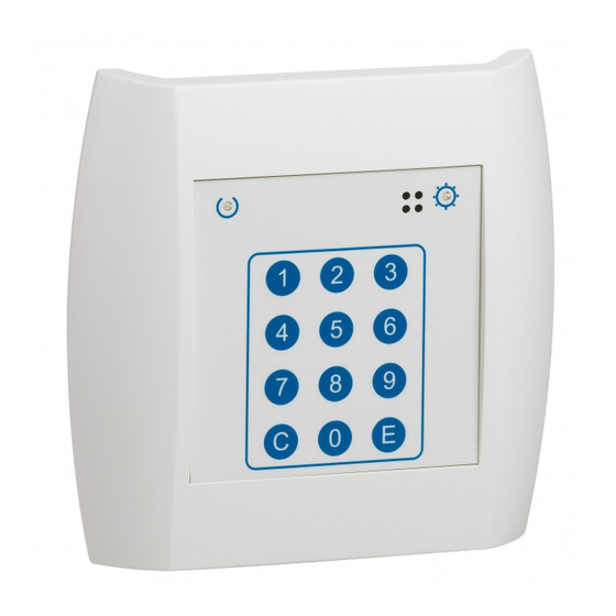
Device presentation and installation (continued) seCUre WanDerIng sYsteM (ContInUeD) antenna Cat no. 766 21 1 Status LED 2 Detection LED Placed as close to the exit as possible, ideally 50 cm from the ground at the side of the door latch, this element detects the presence of a wristband Cat. - Page 7 Wristband Cat. no. 766 20 Activated or deactivated by passing a magnet over the device. To be performed close to the controller Cat. No. 766 22. Worn on the wrist or the ankle, this waterproof wristband is fitted with eyelet closures preventing the person under surveillance from taking it off.
-
Page 8: Secure Wandering System - Auxiliary Elements
Device presentation and installation (continued) seCUre WanDerIng sYsteM - aUXIlIarY eleMents Door contact Cat. no. 431 00 technical characteristics • IP 41 - IK 02 • Operating temperature: -10°C to +70°C • Cable type (to controllers 766 22): 1 x 9/10th pairs The magnetic opening sensor must be connected to the "DOOR"... -
Page 9: Standalone Installation
The controller Cat. No. 766 22 is normally installed in the immediate vicinity of the exit at a height that allows easy access to the keypad. The antenna Cat. No. 766 21 is installed at a height of around 50 cm. - Page 10 standalone installation (continued) eXaMple InstallatIon (ContInUeD) outdoor installation: The secure wandering system is not intended for outdoor installation. However, surveillance of this type of exit is possible where the installation is adapted: - The controller must be installed indoors. - The antenna boxes must be placed in weatherproof enclosures made from non-conductive materials (plastic, PVC, etc.).
-
Page 11: Wiring - Controllers And Antennae
WIrIng - Controllers anD antennae 766 22 431 00 ALARM DOOR LOCK CHAPERONE CONF 4 131 05 1 2 3 4 DCIN MODE 047 60 766 21 766 21... -
Page 12: Operating Modes
standalone installation operatIng MoDes Chaperone Mode selection The controller must be set to chaperone mode in The changeover from surveillance mode to intruder order to allow a wristband wearer to go through an exit mode and back can be controlled by the state of this without setting off the alarm. -
Page 13: System Installation
The controller Cat. No. 766 22 is normally installed in the immediate vicinity of the exit at a height that allows easy access to the keypad. The antenna Cat. No. 766 21 is installed at a height of around 50 cm. - Page 14 system installation (continued) eXaMple InstallatIon (ContInUeD) outdoor installation: The secure wandering system is not intended for outdoor installation. However, surveillance of this type of exit is possible where the installation is adapted: - The controller must be installed indoors. - The antenna boxes must be placed in weatherproof enclosures made from non-conductive materials (plastic, PVC, etc.).
-
Page 15: Wiring - Controller/Antennae And Door Unit
WIrIng - Controller/antennae anD Door UnIt 766 22 ALARM DOOR 766 06 431 00 LOCK CHAPERONE 15 16 17 18 19 20 CONF 1 2 3 4 DCIN 4 131 05 MODE 047 60 766 21 766 21... -
Page 16: Operating Modes
system installation (continued) operatIng MoDes Chaperone Mode selection The controller must be set to chaperone mode for a The changeover from surveillance mode to intruder set time period (chaperone period) in order to allow a mode and back can be controlled by the state of this wristband wearer to go through an exit without setting input. -
Page 17: Commissioning
Commissioning FaCtorY settIngs For the initial commissioning or following a software update or restoration of the default settings (code 9090) the controller is started up with the standard operating settings which have the following values: • Controller address: 1 • Chaperone period: 15 seconds •... -
Page 18: Parameter Setting
Commissioning (continued) paraMeter settIng The parameters can easily be set for the system using simple codes that provide access to the different parameter setting steps. A parameter setting is changed by entering the following on the controller keypad: • 1 - The setting code (90XX codes) •... - Page 19 Code parameter 9005 Mode change mechanism: Allows the user to choose whether the changeover from intruder mode to surveillance mode is performed by entering codes on the keypad (value 1) or by analysing the mode selection input (value 0). Example: Mode selection by entering codes on the keypad: 9005 e 1 e 9006 locking control: Operation with locking control (value 0) or with release control (value 1).
- Page 20 Commissioning (continued) settIng the antennae Due to the low power level radiated by the wristband transmitters setting the sensitivity level of the antenna must be carried out under conditions that are as close as possible to normal system usage. Proceed as follows in order to set the antenna: •...
-
Page 21: Operation In Day Mode (Surveillance)
operation operatIon In DaY MoDe (sUrveIllanCe) This mode is activated using code 9031 or a timing device connected to the "MODE" terminals. The controller must generate an alarm in the event that a resident fitted with a wristband escapes. When in rest mode, the power supply indicator light is on constantly and the operation indicator light is permanently off. The alarm output is active and the locking output inactive. -
Page 22: Operation In Night Mode (Intruder)
operation (continued) operatIon In nIght MoDe (IntrUDer) This mode is activated using code 9030 or a timing device connected to the "MODE" terminals. This mode is used when the controller needs to generate an alarm if the exit is opened or crossed by anyone (with or without a wristband). -
Page 23: Illuminated Signals
IllUMInateD sIgnals The controller status is indicated via two indicator lights. When the green indicator light is on constantly the system is switched on. Flashing indicates that there is a system fault which requires the controller and the antennae to be checked. The yellow operation indicator light shows the system status with different types of flashing (see the diagram below). -
Page 24: Characteristics
Characteristics speCIFICatIons power supply: volt-free contact outputs: • 12 to 24 V= • Locking: 1 A - 24 VA/60 V= max • 150 mA • Alarm: 1 A – 24 VA/60 V= max Illuminated signals: Wristband: • System power ON •... -
Page 25: Usage Codes
Usage codes Control CoDe Option of changing the operating mode by entering a code. A parameter setting is changed by entering the following on the controller keypad: • 1 - Enter the code • 2 - E (validation) - C: permet d’annuler une saisie en cours. Code Control 9030... - Page 26 Head office: 128, av. du Maréchal-de-Lattre-de-Tassigny 87045 Limoges Cedex - France Tel: +33 5 55 06 87 87 Fax: +33 5 55 06 88 88 www.legrand.com...
Need help?
Do you have a question about the 766 21 and is the answer not in the manual?
Questions and answers