Table of Contents
Advertisement
Quick Links
Advent XT
Assisted Living Call Management System
_________________________________________________________________________________________________________________
Tynetec, a business unit of Legrand Electric Ltd
Cowley Road, Blyth Riverside Business Park, Blyth, Northumberland, NE24 5TF.
T: +44 (0)
1670 352 371 www.tynetec.co.uk
_______________________________________________________________________________________________________________
Trusted Technology
Caring for People
Installation Manual
Tynetec operates a policy of continual product improvement and
Reserves the right to modify the specification of its products.
If any variation to the details in this document are suspected please
contact Tynetec's Technical Support on 01670 352371.
Doc No. FM0410 issue N Page 1
Advertisement
Table of Contents

Related Manuals for LEGRAND tynetec Advent XT


Summary of Contents for LEGRAND tynetec Advent XT
- Page 1 If any variation to the details in this document are suspected please contact Tynetec’s Technical Support on 01670 352371. Tynetec, a business unit of Legrand Electric Ltd Cowley Road, Blyth Riverside Business Park, Blyth, Northumberland, NE24 5TF. T: +44 (0) 1670 352 371 www.tynetec.co.uk...
- Page 2 INDEX Section Topic Page Safety Instructions Regulatory Information Maintenance & Care Related Documentation Introduction System Overview Controller Installation Network Wiring Network Load Considerations Network Termination Board Network Cable Colour Code PA Amplifier Installation Intercom Unit Installation Intercom Unit Auxiliary Devices Intercom Unit DIL Switches &...
-
Page 3: Safety Instructions
1. SAFETY INSTRUCTIONS Read and understand these instructions before commencing an installation. Keep these instructions for future reference. To reduce the risk of electric shock, do not disassemble this product unless you are qualified. Opening or removing covers may expose you to dangerous voltages or other hazards. No user serviceable parts inside. -
Page 4: Regulatory Information
2. REGULATORY INFORMATION This symbol on the product indicates it complies with all relevant EU Directives as required by law. Radio & Telecommunication Terminal Equipment; R&TTE Directive 1999/5/EC Safety of Information Technology Equipment; EN 60950-1:2006+A12:2011 Electro Magnetic Compatibility; EMC 2004/108/EC Restriction of Hazardous Substances;... -
Page 5: Related Documentation
4. RELATED DOCUMENTATION This manual provides information regarding the installation of the Advent XT system. You can request copies of the related documentation listed below from Tynetec’s customer support team or download from Tynetec’s on-demand website: http://www.tynetec.co.uk/on-demand/technical-support/advent-xt/ • Wiring Diagrams with Spectalink IP-DECT (Drawing No. ZXT100 ISS M) •... - Page 6 5. INTRODUCTION The Advent xt is an alarm monitoring and communication system designed specifically for grouped housing schemes. A typical installation will comprise of an Advent xt controller with intercom units and peripheral devices connected on a bus wiring network. Alarm calls are reported to an onsite manager via a cordless or desk telephone, calls may also be reported via a PSTN line to a mobile phone/remote Alarm Receiving Centre (ARC) or via the Ethernet to a digital ARC.
-
Page 7: System Overview
6. SYSTEM OVERVIEW Part No. Description Notes ZXT100 Advent xt Controller inc battery standby & Digital Communicator ZXT122 Advent xt Ethernet InterfaceMK3) stores Telecare data for remote analysis ZXT155 Advent xt PA Amplifier typically 80 PA intercoms per PA amplifier ZXT201 Standard Intercom ZXT206... - Page 8 6. SYSTEM OVERVIEW INTERCOM UNITS Up to 255 intercom units can be connected on the system network. Each intercom can have ceiling pullcords, smoke detectors and PIR’s (for activity or intruder monitoring) connected as standard. An additional 4 inputs are available on intercoms without a door entry telephone connected.
-
Page 9: Controller Installation
7. CONTROLLER INSTALLATION The Advent xt controller is housed in a 400x500x75mm (HxWxD) steel enclosure with an integral power supply unit and 2 rechargeable standby batteries. 4 x 20mm KNOCKOUTS ON TOP FACE 3 x 20mm KNOCKOUTS ON R/H SIDE 240V AC ... -
Page 10: Telephone Connection
7. CONTROLLER INSTALLATION 27V SMPSU MODULE The controller includes a 27V/150W (5.6A) switched mode power supply unit with solid state overload protection. With the mains supply ON the green output healthy LED should be illuminated. The output voltage is factory set to 27.5V DC (with the batteries disconnected) using a DVM across V+/V-. -
Page 11: Network Wiring
8. NETWORK WIRING A basic Advent xt system requires a minimum of 4 twisted pairs common to all intercom units - if public address (PA) or door entry telephones are specified then 5 twisted pairs are required. On new installations a 6 pair CW1308 BT spec cable is recommended. Plan the network route to minimise cable length using the intercom units to join the cable thereby avoiding additional joint boxes in corridors or roof areas etc. -
Page 12: Network Load Considerations
9. NETWORK LOAD CONSIDERATIONS It is very important to take voltage drop across the system network into consideration when planning an installation. It is the cable resistance on the power supply wiring that gives rise to voltage drop - the longer the cable run and the larger the current requirement, the larger the voltage drop. -
Page 13: Network Termination Board
10. NETWORK TERMINATION BOARD The Advent xt termination board provides the interface between the main CPU board and the site wiring network. RS232 LINK 1-6 INPUTS ALTERA PORT 2 SETTINGS OUTPUTS FUSES NETWORK NETWORK ... - Page 14 10. NETWORK TERMINATION BOARD FIRE ALARM INPUT (issue “A-D” A00415 Amp Board & V1.0x Firmware) When 0V is applied to input 4 a “999” fire alarm call will be reported via the current operating mode. If input 4 is still active when this call has been answered and cleared a fire tone will start to sound through all intercoms (unless disabled in the General Set-up programming).
-
Page 15: System Network
10. NETWORK TERMINATION BOARD PA & DOOR ENTRY The optional PA amplifier and/or door entry panels are connected to the termination board; Terminal Function Enable signal connected to PA amplifier board DECT audio connected to PA amplifier input DECT audio 0V reference RS485 + RS485 bi-directional data bus RS485 -... -
Page 16: Network Cable Colour Code
11. NETWORK CABLE COLOUR CODE CW1308 NETWORK CABLE The recommended colour code using a 6 pair CW1308 BT spec cable is given below; Pair No. Diameter Colour Signal White/Blue 0.5 mm Blue/White 2 x 0.5 mm White/Orange Pair White/Green RS485+ 0.5 mm Green/White RS485-... -
Page 17: Pa Amplifier Installation
12. PA AMPLIFIER INSTALLATION The optional PA amplifier & SMPSU (P/No. ZXT155) allows the onsite manager to broadcast public address announcements through all intercoms simultaneously. Note; PA intercoms (P/No. ZXT206) must be fitted in all dwellings. One PA amplifier & SMPSU can drive approx. 80 intercoms, for larger systems a second ZXT155 will be required and the site PA wiring must be split into two legs. -
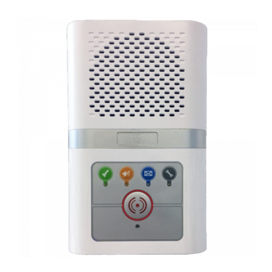
Page 18: Intercom Unit Installation
13. INTERCOM UNIT INSTALLATION The intercom unit should be wall mounted in a central location within each dwelling. Screw fix the intercom rear securely to the wall using the 4 holes marked “A”. The 2 holes marked “B” can be used for an embedded box. Ensure the case is not twisted as this may prevent the lid fitting correctly. -
Page 19: Intercom Unit Auxiliary Devices
14. INTERCOM UNIT AUXILIARY DEVICES The intercom has the facility to connect ceiling mounted pullcords, smoke detectors, PIR detectors and a hard of hearing strobe light within each dwelling. Four additional inputs are available provided there is no door entry telephone or strobe light connected to the intercom. -
Page 20: Pir Detectors
14. INTERCOM UNIT AUXILIARY DEVICES PIR DETECTORS PIR detectors are supplied by others. They can be powered from the network wiring auxiliary 12V supply. They must have normally closed clean contacts which open when movement is detected. 2 PAIR If more than one PIR is installed in the same INTERCOM 12V TO PIR dwelling the normally closed contacts must be... -
Page 21: Intercom Unit Dil Switches & Link Settings
15. INTERCOM UNIT DIL SWITCHES & LINK SETTINGS Before fitting the intercom front the “Address” and “Options” DIL switches must be set. The jumper links LK1, LK2 & LK3 must also be set in the correct position. INTERCOM ADDRESS DIL SWITCH The intercom Address must be set sequentially using an 8 bit binary code starting from “1”... -
Page 22: Operation
16. REMOTE INTERCOM UNIT INSTALLATION The remote intercom (P/No. ZXT221) can be connected to any standard intercom if a second speech unit is required within a dwelling. The remote intercom is also available with PA facility (P/No. ZXT226) if all call speech/fire tone is required through both intercoms. - Page 23 17. FITTING & REMOVING THE INTERCOM FRONT Before fitting the intercom front; set the Address and Options DIL switches and check links LK1-3 are fitted in the correct positions. Ensure all cables are properly terminated and secure spare wires in the clips provided. FITTING THE INTERCOM FRONT Locate the 2 top corners of the intercom front over the 2 top corners of the intercom back, swing downwards and clip together ensuring the pullcord is located in its slots.
-
Page 24: Intercom Unit Test Mode
18. INTERCOM UNIT TEST MODE The intercom unit Test Mode allows all input devices to be tested on a per-flat basis without putting a call on the system. Once in Test Mode the intercom will beep as each device is activated, the system printer will log each test with the flat number, device type, time and date. -
Page 25: Manager Callpoint Installation
19. MANAGER CALLPOINT INSTALLATION The Manager Callpoint (P/No. ZXT250) is an external speech unit used to initiate a call from outside the building. It is connected to the system network similar to a standard intercom. ADVENT xt NETWORK ZXT250/255 MANAGER CALLPOINT 1 2 3 4 5 6 7 8 1 2 3 4 5 6 7 8 FIT 4K7 RESISTOR ACROSS... -
Page 26: Lift Callpoint Installation
20. LIFT CALLPOINT INSTALLATION The Lift Callpoint (P/No. ZXT260) is used to initiate a call from inside a lift car. The callpoint requires four wires via the lift company’s travelling cable to an interface unit in the motor room. The interface unit is connected to the system network similar to a standard intercom. -
Page 27: Network Connection
21. STATUS MODULE INSTALLATION The Advent xt Status Module (P/No. ZXT300) is normally fitted in the Managers office and provides the facility to manually switch the system operating mode. Green, amber and red LED indicators identify the current mode; under certain conditions the system may change its mode automatically i.e. -
Page 28: Manager's Display Panel Installation
22. MANAGER’S DISPLAY PANEL INSTALLATION The optional Manager’s Display Panel (P/No. ZXT315) is a wall mounted 10.4” touch-screen monitor used to display all system activity and log all events with the time and date. Only one Manager’s Panel can be connected per system. From November 2014 the Manager’s Panel is supplied with a battery backed 12V/2A DC PSU in a separate metal box. -
Page 29: Network Receiver Installation
23. NETWORK RECEIVER INSTALLATION Up to 16 x 169MHz Network Receivers (P/No. ZXT325) can be installed throughout a site to provide radio coverage for personal pendants or other Altec radio devices. BNC CONNECTOR FOR AERIAL ABS ENCLOSURE 160x80x55mm RESET ➔... -
Page 30: Aerial Connection
23. NETWORK RECEIVER INSTALLATION 169MHz SEPARATION To obtain maximum coverage it is very important that there is a minimum of 3 METRES SEPARATION between the Network Receiver, its own Aerial and any DECT Base Station or Repeater. Failure to follow these recommendations will result in significantly reduced radio coverage. - Page 31 24. ZONED NETWORK RECEIVER INSTALLATION Zoned Network Receivers help the onsite Manager to identify which area of the building a pendant alarm has come from. 169MHz Zoned Network Receivers were introduced in September 2011 and can only be used with Advent xt Controller firmware V2.03a onwards. Full radio coverage must first be achieved using standard ZXT325 Network Receivers with W06250 1/2 Wave Aerials, then a limited number of ZXT326 Zoned Network Receivers can be deployed around the site to give localised radio coverage.
- Page 32 24. ZONED NETWORK RECEIVER INSTALLATION ENABLE RSSI PRINT-OUT Firstly set the Advent xt system to print the Zoned Network Receiver Signal Strengh (RSSI) using the DECT handset; 1. Press the LINE key, enter 8 1 and wait for the “Ready” prompt in the earpiece 2.
-
Page 33: Digital Door Panels
25. DIGITAL DOOR PANEL INSTALLATION The Advent xt system can be upgraded to include a door entry facility with the addition of digital door panels and telephone handsets. Visitors can call residents direct from the door panels with full duplex speech via door entry telephones. -
Page 34: Link Settings
25. DIGITAL DOOR PANEL INSTALLATION TERMINATION See Tynetec Drg No. ZXT100 sheet 3 for detailed wiring connections; DOOR PANEL AMPLIFIER BOARD Terminal Function Connection IP 1 Play Welcome Message 0V Trigger IP 2 No Function Not Connected RELAY Activates for duration of call Not Connected 1 pair CW1308 to Warden Call Loudspeaker Audio... - Page 35 25. DIGITAL DOOR PANEL INSTALLATION PROGRAMMING The number of door panels, Access Codes, Trade Times and Call Transfer Times must be set in the “Door Entry Setup” programming - see the Advent xt Programming Manual (Tynetec Doc No. FM0411). VOLUME ADJUSTMENT The 5 potentiometers VR2 - VR6 in each door panel are used to independently adjust the audio level to/from the door entry and warden call system.
-
Page 36: Door Entry Telephone Installation
26. DOOR ENTRY TELEPHONE INSTALLATION Door entry telephones (P/No. ZFT220/221) are connected to the intercom unit within each dwelling. When called the telephone will ring for a preset time or until the handset is lifted. Speech is private between the door panel and the dwelling called and cannot be overheard by other users from their handsets or visitors at other door panels. - Page 37 26. DOOR ENTRY TELEPHONE INSTALLATION TERMINATION Intercom Telephone Function Wire Colour Cable Terminal Terminal ENABLE dual handset enable output STROBE strobe -ve output audio to door signal white/blue 1 pair CW1308 audio to phone signal blue/white SDATA data white/green 1 pair CW1308 SCLK clock...
- Page 38 27. COMBINED INTERCOM INSTALLATION Combined intercoms provide both warden call and door entry functions in a single unit. The ZXT28x models are available with and without PA/Extracare, The ZXT290 model has PA as standard and Bluetooth for use with the optional BLE Remote Control –...
-
Page 39: Link Options
27. COMBINED INTERCOM INSTALLATION ADDRESS DIL SWITCH The combined intercom Address must be set sequentially using an 8 bit binary code starting from “1” in the lowest flat number on the site. 1 2 3 4 5 6 7 8 1 2 3 4 5 6 7 8 Note: binary “0”... -
Page 40: Privacy Mode
27. COMBINED INTERCOM INSTALLATION HARD OF HEARING STROBES & VOLUME Two hard of hearing strobes can be connected to a combined intercom. A clear strobe (P/No. ZSL047) can be connected to indicate a door entry call and a blue strobe (P/No. ZSL046) can be connected to indicate when the warden is calling. Note;... - Page 41 28. BLE REMOTE CONTROL INSTALLATION The BLE Remote Control can be used with the ZXT290 combined intercom to answer door entry calls and release the door lock. It can also be used to select privacy mode, I’m OK and play a message waiting. Part No.
-
Page 42: Door Open Alarm Installation
29. DOOR OPEN ALARM INSTALLATION The Door Open Alarm (P/No. ZDA025) can be connected to an Advent xt system to initiate an alarm call when an Emergency Exit door is left open. The Door Open Alarm must be connected via an Advent xt intercom unit to provide an alarm location message and 2 way speech. - Page 43 30. BT LINE SELECTOR INSTALLATION The BT Line Selector (P/No. ZXT330) can be connected to the Advent xt controller if a second dedicated BT line or a GSM cellular terminal is specified for fail safe operation. If the primary line fails the secondary line will automatically be selected, once the primary line is restored the system will automatically switch back.
-
Page 44: Dil Switch Settings
31. NETWORK DATA REPEATER INSTALLATION The Network Data Repeater (P/No. ZXT340) can be connected into the Advent xt RS485 network to boost the data signal on cable runs over 1200 metres. ➔ POWER IN ➔ RS485 DATA IN RS485 DATA OUT INSTALLATION The Network Data Repeater is housed in a wall mounted ABS enclosure;... - Page 45 32. ETHERNET INTERFACE KIT INSTALLATION The optional Ethernet Interface Kit stores all alarm and Telecare data with the time and date of each event on a local Memory Card. The stored data can be downloaded and analysed using Tynetec’s I-Care software. There are 3 generations of interface kits as the Rabbitcore Module/Memory Card has changed over the years.
-
Page 46: Led Indicators
32. ETHERNET INTERFACE KIT INSTALLATION A00382 EXPANDER BOARD THE RCM3365/RCM3900 RABBITCORE MODULE IS PLUGGED ON TOP OF THE A00382 BOARD MEMORY CARD SLOT LED’s 1 - 6 SEE TABLE BELOW ➔ RJ45 ETHERNET PORT OPTION SELECT DIL SWITCH SEE TABLE BELOW ➔... - Page 47 33. DIGITAL COMMUNICATOR INSTALLATION The optional Digital Communicator (P/No. ZXT130) allows the Advent xt to communicate digitally via the internet to a digitally enabled Alarm Receiving Centre (ARC). The Advent xt can also retain the PSTN analogue connection which will then be used as a secondary connection.
-
Page 48: Ethernet Connection
33. DIGITAL COMMUNICATOR INSTALLATION ETHERNET CONNECTION The Ethernet port (CON2) on the Digital Communicator should be connected to an ADSL router if offsite calls are being reported to a digital ARC. The following must be specified when setting-up the Ethernet connection to a digital ARC; 1. -
Page 49: Specification - Controller
35. SPECIFICATION - CONTROLLER Tynetec Part No. ZXT101 EMC Approval EN 55022 Safety Approval EN 60950 Social Alarm Standard EN 50134 System Removable Memory Tynetec Dataflash Card (Part No. A00480) Real Time Clock Auto-DST adjustment LED Indicators Power/Data/Line Seize Protocols BS8521/BS7369/TTNew/TT92 (+NOW IP with Digital Communicator) Inputs 4 x N/O inputs (switched 0V) -
Page 50: Specification - Pa Amplifier
36. SPECIFICATION - PA AMPLIFIER Tynetec Part No. ZXT155 EMC Approval EN 55022 Safety Approval EN 60950 System Amplifier Power Output 68W Max Audio Transformer 100V Line Step-up LED Indicators Power/Data Data RS485 Power Supply Manufacturer/Model No. Ecopac SE-100-15 (Tynetec P/No. W00586) Input 176-264V AC 47/63Hz Output... -
Page 51: Specification - Intercom
37. SPECIFICATION - INTERCOM Tynetec Part No’s ZXT201/206/211/216/221/226/280/282/284/286/290 EMC Approval EN 55022 Safety Approval EN 60950 Max No. Intercoms Data Connection RS485 (19200 Baud) Power Requirement 24V DC @ 2mA (standby) Audio Channel Handsfree Voice Switched 8 Way Address DIL Switch Set Binary ID 8 Way Options DIL Switch Enable Auxiliary Devices... - Page 52 38. SPECIFICATION - BLE REMOTE CONTROL Tynetec Part No. ZXT935 EMC Approval EN 55022 Safety Approval EN 60950 Compatibility ZXT290 Combined Intercom with PA & Bluetooth (BLE) Protocol Bluetooth Low Energy (BLE) V4.1 Frequency/Data Rate 2.4GHz 1 Mbit/s Transmit Power 2.5mW (Class 2) Range 10 metres Max...
- Page 53 39. SPECIFICATION - MANAGERS CALLPOINT Tynetec Part No’s ZXT250 Standard, ZXT255 Custom Engraved EMC Approval EN 55022 Safety Approval EN 60950 Data Connection RS485 (19200 Baud) Power Requirement 24V DC @ 2mA (standby) Audio Channel Handsfree Voice Switched 8 Way Address DIL Switch Set Binary ID 8 Way Options DIL Switch Set 1-8 OFF (not used)
-
Page 54: Specification - Lift Callpoint (Flush Stainless Steel)
40. SPECIFICATION - LIFT CALLPOINT (FLUSH STAINLESS STEEL) Tynetec Part No’s ZXT260 Standard, ZXT265 Custom Engraved EMC Approval EN 55022 Safety Approval EN 60950 Data Connection RS485 (19200 Baud) Power Requirement 24V DC @ 2mA (standby) Audio Channel Handsfree Voice Switched 8 Way Address DIL Switch Set Binary ID Loudspeaker... -
Page 55: Specification - Lift Callpoint (Surface Abs)
41. SPECIFICATION - LIFT CALLPOINT (SURFACE ABS) Tynetec Part No’s ZXT271 EMC Approval EN 55022 Safety Approval EN 60950 Data Connection RS485 (19200 Baud) Power Requirement 24V DC @ 2mA (standby) Audio Channel Handsfree Voice Switched 8 Way Address DIL Switch Set Binary ID Loudspeaker 35 Ohm 0.5 Watts... - Page 56 42. SPECIFICATION - 169MHz NETWORK RECEIVER Tynetec Part No. ZXT325 Standard & ZXT326 Zoned EMC Approval EN 55022 Safety Approval EN 60950 Radio Approval R&TTE 1999/5/EC Radio Frequency 169.48125MHz Radio Range 75 metres typical (indoor) Max No. NTR’s per Site Data Connection RS485 Power Requirement...
-
Page 57: Specification - Manager's Display Panel
43. SPECIFICATION - MANAGER’S DISPLAY PANEL Manager’s Display Panel Tynetec Part No. ZXT315 EMC Approval EN 55022 Safety Approval EN 60950 Display Size 10.4” Type VGA TFT Colour Resolution 640 x 480 pixels Backlight Touch Type Resistive Memory 1GB Industrial SLC SD Card Operating System Windows CE 6.0 Power... -
Page 58: Specification - Door Entry Panel
44. SPECIFICATION - DOOR ENTRY PANEL Tynetec Part No’s ZXT411 Standard, ZXT422 with Emergency Button (AHA Only) EMC Approval EN 55022 Safety Approval EN 60950 Data Connection RS485 Power Requirement 24V DC @ 30mA standby (250mA active) Audio Channel Handsfree Voice Switched (simplex with combined intercoms) 8 Way DIL Switch 1 to 4 = Set Binary ID, 5/6/7/8 all ON LK1 = Fail Secure or Fail Safe Lock Type, LK2 = Expander Fitted,... -
Page 59: Specification - Door Entry Telephone
45. SPECIFICATION - DOOR ENTRY TELEPHONE Tynetec Part No’s ZFT220 for Single Handset, ZFT221 for Master and Extension EMC Approval EN 55022 Safety Approval EN 60950 Data Connection SDATA & SCLK Power Requirement 10V DC @ 3mA standby (15mA active) 3 Jumper Setting LK1/LK2 = SDATA &... -
Page 60: Specification - Line Selector
46. SPECIFICATION - LINE SELECTOR Tynetec Part No. ZXT330 EMC Approval Safety Approval Features Power Requirement 12V DC @ 40mA active (0mA standby) BT47 Relay Fully sealed DPDT contacts rated 2A @ 30V DC Telecom Connectors 3 x BT Type 431A Sockets Screw Terminals 12V &... -
Page 61: Specification - Door Open Alarm
48. SPECIFICATION - DOOR OPEN ALARM Tynetec Part No. ZDA025 EMC Approval Safety Approval Features Power Requirement 24V DC @ 50mA (standby) Jumpers LK1&LK2 Cut LK1 and fit LK2 for 12V DC supply Jumper LK3 Cut to isolate Piezo sounder Potentiometer VR1 Adjust delay before alarm 1 second to 5 minutes Piezo Sounder... -
Page 62: Specification - Master Strobe
49. SPECIFICATION - MASTER STROBE Tynetec Part No. ZSL045 EMC Approval Safety Approval Features Power Requirement 10V DC @ 2mA (standby) 90mA active Data Connection SDATA & SCLK Max No. Strobes 1 per intercom Strobe Lens Colour Blue Strobe Lamp Xenon Strobe Flash Rate 100 per minute... -
Page 63: Amendments Record
51. AMENDMENTS RECORD The table below lists significant changes to this manual; Issue Amendments Date Connection details for hard of hearing strobe option added to door entry telephone. 03/04/06 169MHz Network Receivers and Door Open Alarm connection details added. Controller requires V1.03a 07/07/06 firmware for 169MHz Network Receivers.
Need help?
Do you have a question about the tynetec Advent XT and is the answer not in the manual?
Questions and answers