Table of Contents
Advertisement
Advertisement
Table of Contents

Summary of Contents for Grundfos Conlift
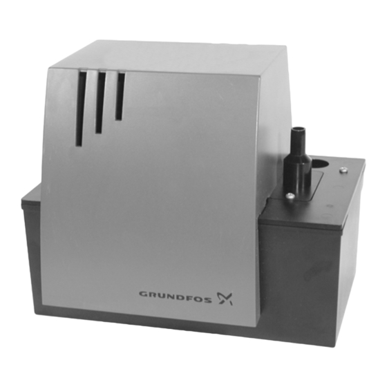
- Page 1 GRUNDFOS INSTRUCTIONS Conlift Installation and operating instructions...
- Page 2 We Grundfos declare under our sole responsibility that the lifting Wir Grundfos erklären in alleiniger Verantwortung, dass die station Conlift, to which this declaration relates, is in conformity with Hebeanlage Conlift, auf die sich diese Erklärung bezieht, mit den the Council Directives on the approximation of the laws of the EC...
- Page 3 Conlift Installation and operating instructions Montage- und Betriebsanleitung Notice d’installation et d’entretien Istruzioni di installazione e funzionamento Installatie- en bedieningsinstructies Monterings- og driftsinstruktion Instrukcja montażu i eksploatacji...
-
Page 4: Table Of Contents
CONTENTS 2. General description Page The Grundfos Conlift is a compact lifting station with built-in non-return valve; it works automatically. The Delivery Conlift is ready for installation. General description Applications 2.1 Applications Function The Conlift is designed for the pumping of conden-... -
Page 5: Function
3. Function The condensate flows by natural gravitation through a hose into the lifting station, see section 4. Installa- tion. When the liquid level in the collecting tank reaches 60 mm, the pump starts automatically via pressure switch 1. When the liquid level falls below 35 mm, the pump stops. -
Page 6: Installation
(in compliance with IP X4). 4.2 Lifting station The Conlift must be mounted horizontally. The Conlift can be mounted on the floor or on the wall. Drilling template for the holes for wall mounting can be found at the end of this booklet. - Page 7 Conlift upside down. mounting). This prevents the acid in the collecting tank from If the Conlift is installed in a room where there is a spilling out and causing damage. risk of flooding, the angular mounting brackets must be used.
-
Page 8: Connection Of Inlet And Discharge Hoses
• If the Conlift is positioned below sewer level, the hose must have a return loop at the highest point. The lower edge of the loop must be 10 to 20 cm above sewer level (the sewer level usually corre- sponds to the street level). - Page 9 4.4.3 External alarm/potential-free contact Before starting work on the Conlift, the electricity supply must be switched off. It must be ensured that the electricity supply cannot be accidentally switched on. Work on electrical systems and compo- nents must only be carried out by a quali- fied electrician.
-
Page 10: Electrical Connection
Function. automatically. Alarm: As standard, the Conlift is fitted with an alarm device Continue the procedure: (buzzer). It is also possible to pass on the alarm indi- 6. To ensure that the alarm level is reached, cation via a potential-free contact. -
Page 11: Maintenance And Service
(pressure switch 2), see also Note: If a Conlift lifting station has been used for a section 3. Function. liquid that is injurious to health or toxic, the lifting sta- The Conlift is now ready for operation. -
Page 12: Components
8. Components Supplied with the unit Beipack: Pos. 51 1 x Pos. 51 1 x Pos. 52 2 x Pos. 52 2 x Pos. 53 4 x Pos. 53 4 x Pos. 54 4 x Pos. 54 4 x Pos. 55 1 x Pos. -
Page 13: Service Kit
8.1 Service kit 8.1.1 Mounting kit Service kit No. 96115902 Pos. no. Quantity Description DIN, grade, remarks Hose, 5 metres Angular mounting bracket ABS/black Wood screw DIN 96 4 x 35, galvanised steel ® Rawlplug S5-5 x 25 mm, PA Hose clamp Black Mounting foot... - Page 14 8.1.5 Pump part Service kit No. 96115906 Pos. no. Quantity Description DIN, grade, remarks Pump housing ABS/black Gasket EPDM/black ® Impeller Hostaform EJOT-PT screw WN 1412, KA 40 x 16 8.1.6 Supply cable with Schuko plug Service kit No. 96115907 Pos.
-
Page 15: Accessories
Description DIN, grade, remarks PC-board with buzzer for pressure switch 8.2 Accessories The following accessories for the Conlift are available from a local supplier. Accessory no. Description Product number 5 metres of PVC hose with 10 mm internal diameter including... -
Page 16: Fault Finding Chart
Replace the fuse. c) Supply cable damaged. The cable must be repaired or replaced by an authorized service workshop or by Grundfos. d) Thermal switch cut out. The motor is not sufficiently cooled. - The cooling slots in the motor cover are covered or clogged. -
Page 17: Technical Data
1. Use the public or private waste collection service. Maximum density 2. If this is not possible, contact the nearest 1000 kg/m³. Grundfos company or service workshop. Operating mode Intermittent operation, S3: 15% according to DIN EN 0530 T1 (i.e. runs for 1.5 minutes and is stopped for 8.5 minutes). - Page 19 Telefax: +60-3-5569 2866 Telefax: +46-31 331 94 60 South Australia 5942 Germany Mexico Switzerland Phone: +61-8-8461-4611 GRUNDFOS GMBH Bombas GRUNDFOS de Mexico S.A. de GRUNDFOS Pumpen AG Telefax: +61-8-8340 0155 Schlüterstr. 33 C.V. Bruggacherstrasse 10 40699 Erkrath Boulevard TLC No. 15 CH-8117 Fällanden/ZH...
- Page 20 Being responsible is our foundation Thinking ahead makes it possible Innovation is the essence 96521370 0406 Repl. 96521370 1005 www.grundfos.com...


Need help?
Do you have a question about the Conlift and is the answer not in the manual?
Questions and answers