Advertisement
Power factor controller
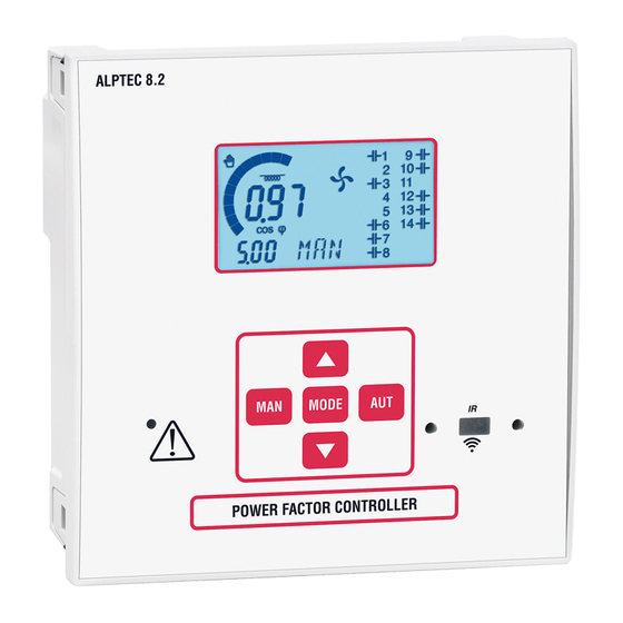
ALPTEC 3.2 – ALPTEC 5.2 – ALPTEC 8.2
CONTENTS
1 - Introduction ..........................................................................................................................................................................................................................2
2 - Description ............................................................................................................................................................................................................................2
3 - Modularity .............................................................................................................................................................................................................................3
4 - IR programming port .........................................................................................................................................................................................................4
5 - Front panel.............................................................................................................................................................................................................................4
6 - Information on the display ..............................................................................................................................................................................................5
7 - Operating modes ................................................................................................................................................................................................................5
8 - Measurements ......................................................................................................................................................................................................................6
9 - Keyboard lock/unlock ........................................................................................................................................................................................................6
10 - "SET" main menu ...............................................................................................................................................................................................................7
11 - First switch-on ....................................................................................................................................................................................................................8
12 - Main programming actions ..........................................................................................................................................................................................8
13 - Parameter tables ...............................................................................................................................................................................................................8
14 - Alarms ................................................................................................................................................................................................................................ 14
15 - Description of alarms ................................................................................................................................................................................................... 14
16 - "CMD" command menu ............................................................................................................................................................................................... 14
17 - "FUN" Ethernet menu .................................................................................................................................................................................................... 15
18 - Position of terminals ..................................................................................................................................................................................................... 15
19 - Technical characteristics .............................................................................................................................................................................................. 16
Read this manual carefully before attempting to install or use the product.
- This equipment must only be installed by qualified staff in accordance with
the applicable regulations, to avoid causing damage to people and property.
- Before starting work on the device, de-energise the power supply and
measurement inputs and short-circuit the current transformers.
- The LEGRAND group will not accept liability for electrical safety if the product
is used incorrectly.
- The products described in this document are likely to be upgraded or
modified without prior warning.
- A breaking and protection device must be located in the immediate
vicinity, within the operator's reach. It must be identified as a device which
disconnects the equipment.
- Clean the device with a soft dry cloth; do not use abrasive products, liquid
detergents or solvents.
CAUTION
PAGE
Advertisement
Table of Contents

Subscribe to Our Youtube Channel
Related Manuals for LEGRAND ALPTEC 5.2


Summary of Contents for LEGRAND ALPTEC 5.2
- Page 1 - Before starting work on the device, de-energise the power supply and measurement inputs and short-circuit the current transformers. - The LEGRAND group will not accept liability for electrical safety if the product is used incorrectly. - The products described in this document are likely to be upgraded or modified without prior warning.
- Page 2 2 - DESCRIPTION - Automatic power factor controller - Mounted on front panel on door or faceplate - Overall controller dimensions: ALPTEC 8.2 ALPTEC 3.2 - ALPTEC 5.2 - Cut-outs for mounting: ALPTEC 8.2 ALPTEC 3.2 - ALPTEC 5.2 - Installation: ALPTEC 3.2/5.2 and 8.2 controllers are designed to be flush-mounted in your installation.
- Page 3 - Versions: • ALPTEC 3.2: control of 3 steps, which can be extended to 6. • ALPTEC 5.2: control of 5 steps, which can be extended to 8. • ALPTEC 8.2: control of 8 steps, which can be extended to 14.
-
Page 4: Ir Programming Port
4 - IR PROGRAMMING PORT – The ALPTEC parameters can be configured via the optical port, using the USB or Wi-Fi connection device. The programming software is available for download via the online catalogue, the smartphone and tablet app from the Apple App Store and Google Play Store. –... -
Page 5: Information On The Display
6 - INFORMATION ON THE DISPLAY Inductif/capacitif Mode Automatique Etat des ventilateurs Etat des sorties Mode Manuel Etat des gradins A chage principal Barre graphique Alarme active A chage A chage secondaire Alpha numérique 7 - OPERATING MODES CAUTION Nombre de gradins Indication du mode TEST... -
Page 6: Keyboard Lock/Unlock
8 - MEASUREMENTS - ALPTEC provides a set of measurements displayed on the alphanumeric screen, related to the cos phi which is always displayed on the main screen. - The button is used to access the various measurements detailed below: Measurement Icon Description... - Page 7 The Legrand Group accepts no liability and the warranty is rendered null and void. (1) Only for ALPTEC 3.2 and 5.2 (2) Only for ALPTEC 8.2...
-
Page 8: First Switch-On
11 - FIRST SWITCH-ON If the primary CT value needs to be set when the controller is first switched on, parameter P.01 is set to OFF: - The main screen then displays the code flashing. - Use to change the value of the primary. - Confirm by pressing MODE - The controller saves the parameter value and starts up in mode... - Page 9 FAN = The relay controls the cooling fan. A01 ... A13 = The relay is energised when the specified alarm is active. P.19 – Cos phi setpoint (target value). Used for standard application. P.20 – Alarm message language. (1) Only for ALPTEC 5.2 and 8.2 CONTENTS...
- Page 10 13 - PARAMETER TABLES (CONTINUED) “ADV” advanced menu Range Code Description P.21 Password enabled 0-999 P.22 User password P.23 Advanced password P.24 Type of connection 3PH Three-phase 1PH Single-phase ON Enabled P.25 Step power setting 0 – 0.10 P.26 + target cos phi tolerance 00:00 P.27 - target cos phi tolerance...
- Page 11 P.22 – With P.21 set to ON, value to be entered to enable access at user level (see password access in section 10). P.23 – For more informations, please contact your Legrand group representative. P.24 – Number of phases in the capacitor bank enclosure.
- Page 12 13 - PARAMETER TABLES (CONTINUED) “ALA” alarm menu Code Description Range P.61 Alarm A01 activation DISC P.62 Alarm A01 delay 0-240 P.63 A01 delay unit of time Min. P.64 Alarm A02 activation DISC P.65 Alarm A02 delay 0-240 P.66 A02 delay unit of time Min.
- Page 13 13 - PARAMETER TABLES (CONTINUED) “ALA” alarm menu (continued) Code Description Range P.82 Alarm A08 activation DISC P.83 Alarm A08 delay 0-240 P.84 A08 delay unit of time Min. P.85 Alarm A09 activation DISC 0-240 P.86 Alarm A09 delay Min. P.87 A09 delay unit of time P.88...
-
Page 14: Description Of Alarms
14 - ALARMS – When an alarm is generated, the screen displays an alarm icon, the alarm code and description in the language selected. – If the navigation buttons in the pages are pressed, the scrolling message showing the alarm information briefly disappears, and then reappears after a few seconds. - Page 15 17 - “FUN” ETHERNET MENU - This menu is only available on ALPTEC 8.2 controllers equipped with the EXTETH module. Code Description Access level Range F.01 IP address • 192.168.1.1 IP1.IP2.IP3.IP4 IP1 0...255 IP2 0...255 IP3 0...255 IP4 0...255 F.02 Subnet mask •...
-
Page 16: Technical Characteristics
Flat panel mounting on a Type 1 Line voltage ±0.5% f.s. ±1 digit enclosure Relay outputs: ALPTEC 3.2 OUTPUTS1 - 2/ALPTEC 5.2 OUTPUTS 1 - 4/ Auxiliary power supply sampled on a phase-neutral voltage system ≤ 300 V. ALPTEC 8.2 OUTPUTS 1-7 ALPTEC3.2... - Page 17 NOTES...
- Page 18 Alpes Technologies BP 332 74934 ANNECY-LE-VIEUX CEDEX...
Need help?
Do you have a question about the ALPTEC 5.2 and is the answer not in the manual?
Questions and answers