Table of Contents

Related Manuals for ZIEHL-ABEGG AM-PREMIUM


Summary of Contents for ZIEHL-ABEGG AM-PREMIUM
- Page 1 AM-PREMIUM(-W) Universal control module for ZIEHL-ABEGG ECblue fans and frequency inverters of the Basic series Operating Instructions Keep for reference! Software version: D1727A / D2263A from version 4.00 L-BAL-E095-GB 1618 Index 006 Part.-No.
-
Page 2: Table Of Contents
5.7.3 AM-PREMIUM-W Wireless Communication ......Potential at control voltage connections ........ - Page 3 9.12 Motor Setup for AM-PREMIUM in ECblue ........
- Page 4 Menu tables ............. . 10.1 Menu table for AM-PREMIUM in ECblue Basic ......
-
Page 5: General Notes
We do not accept any liability for possible errors or omissions in the information contained in data, illustrations or drawings provided. ZIEHL-ABEGG SE is not liable for damage due to misuse, incorrect use, improper use or as a consequence of unauthorized repairs or modifications. -
Page 6: General Description
Note: The AM-PREMIUM-W module is intended exclusively for integration and utilisation in host devices (fans and converters) from ZIEHL-ABEGG. Function By plugging on the “AM-PREMIUM” module, the fan / frequency inverter becomes a full universal controller. The module has two analog inputs (e.g. for sensors), one analog output and a MODBUS interface. -
Page 7: Mounting The Module
Permissible tightening torque of connection terminals M = 0.24 Nm. " When an AM-PREMIUM- module is installed in a fan or converter from ZIEHL-ABEGG, the " “EM-W” enclosed FCC/IC label inside must be stuck to the housing of the terminating device. -
Page 8: Electrical Installation
“E3 / T3” must be paid attention to no polarity. For a high interference immunity a capacitor must be connected directly to the sensor (1 nF parallel). With ZIEHL-ABEGG temperature sensors type TF.. (KTY81-210) the capacitor is inte- grated. - Page 9 Operating Instructions AM-PREMIUM(-W) – model series Electrical installation • Type A-G-247NW, Part.-No. 380090, handheld terminal A-G-247NW + 3,3 V IRDA-RXD IRDA-TXD IRDA-SD (D+) (D-) + 5 V AM-PREMIUM (D+) (D-) 11.02.2014 v_prem_modul_link_terminal.vsd The voltage supply of the terminal is made by the accumulators inserted there or the plug power supply unit.
-
Page 10: Digital Inputs "D1" And "E1 = D2
Electrical installation Digital inputs “D1” and “E1 = D2” In the case of use of the module AM-PREMIUM two digital inputs can be programmed. When inserting the module the analog input “E1” becomes automatically to the second digital input “D2”. -
Page 11: Am-Premium-W Wireless Communication
The type A-G-247NW hand-held terminal can communicate wireless with the type AM-MODBUS-W communications module ( Operating Instuctions A-G-247NW: AM-PREMIUM App's / Configuration Online / Wireless). In a hard-wired system, wireless communication is primarily designed in order to have a second interface for communicating with the device (e.g., for configuration and diagnostics). -
Page 12: Potential At Control Voltage Connections
Operating Instructions AM-PREMIUM(-W) – model series Electrical installation Radio control key (0 - 9999) Different from RS-485 communication, wireless communication also has a radio control key (0 - 9999). This radio control key is used to encode the messages and ensures that several networks can be operated in mutually overlapping radio ranges. -
Page 13: Operating By Terminal
Operating Instructions AM-PREMIUM(-W) – model series Operating by terminal 6 Operating by terminal Menu operation Display after turning on the voltage supply. description for menu language English = “GB” (delivery status). Switch over between “Start” and *Actual value with Escape Example for mode 1.01... -
Page 14: Example For Programming Mode 2.01 In "Base Setup
Operating Instructions AM-PREMIUM(-W) – model series Operating by terminal Selection of the menu group (e.g. Base setup) to the right through the ▼-key, to the left through the ▼-key. You can go to the menu items in the menu groups (e.g. mode of operation) by using the P key. Use the arrow keys to move up and down within the menu group. -
Page 15: Base Setup
Operating Instructions AM-PREMIUM(-W) – model series Base setup 7 Base setup Select operation mode Information Simple installation is possible through the selection of the preprogrammed mode of operation. This determines the basic function of the device; factory setting 1.01 = speed controller (activation via 0 - 10 V signal). -
Page 16: External Setpoint / External Speed Setting In Manual Operation
Operating Instructions AM-PREMIUM(-W) – model series Base setup Mode and Signal to E1, E3 1.01 2.01 2.03 3.01 3.02 4.01 5.01 6.01 0 - 10 V TF.. MBG..-I DSG 0 - 10 V MAL 0 - 10 V 0-10 V 10 k DSG.. -
Page 17: Start-Up
Operating Instructions AM-PREMIUM(-W) – model series Start-up 8 Start-up Prerequisites for commissioning Attention! 1. You must mount and connect the device in accordance with the operating instructions. 2. Double check that all connections are correct. 3. Make sure that no persons or objects are in the fan's hazardous area. -
Page 18: Programming
Operating Instructions AM-PREMIUM(-W) – model series Programming 9 Programming Speed controller 1.01 9.1.1 Base setup 1.01 Base setup Base setup Mode Factory setting Mode: 1.01 Mode E2 Analog In Selection: 0 - 10 V, 0 - 20 mA, 4 - 20 mA, KTY, PT1000 (Inverting... - Page 19 Operating Instructions AM-PREMIUM(-W) – model series Programming Diagram setting signal and output voltage (Idealized principle diagram) 100 % Min. 0 % Max. = 100 % Min. 35 % Max. = 85 % 50 % Min. 0 – 10 V 10 – 0 V 0 –...
-
Page 20: Temperature Control 2.01
Operating Instructions AM-PREMIUM(-W) – model series Programming Diagram setting signal and output frequency [Hz] n-min 10 Hz n-max. = 50 Hz n-min 20 Hz n-max. = 45 Hz n-min OFF n-max. = 50 Hz = 5 Hz = 6 Hz Analog In 1 0...10 V... -
Page 21: Settings For Operation Modes 2.01
Operating Instructions AM-PREMIUM(-W) – model series Programming E3 Function (only for special applications) • Function = External Setpoint e.g. via external signal (0 - 10 V) instead of E3 Function “Setpoint1” “E2 Analog In” “KTY or PT1000” – For sensor type : 0 - 10 V -50.0...+140 °C. -
Page 22: Information
Operating Instructions AM-PREMIUM(-W) – model series Programming Pband Narrow control range = Short control times Wide control range = Longer control times and more stable control Pband Passive sensor type “KTY”, “PT1000” Setting range: 0 - 200.0 K (Kelvin) Factory setting: 5.0 K, (at 2.02... -
Page 23: Functional Diagrams Temperature Control
Operating Instructions AM-PREMIUM(-W) – model series Programming 9.2.3 Functional diagrams temperature control Example 1: Temperature control in factory setting “Cooling function” (Idealized principle diagram) 100 % Min. 0 % Max. = 100 % Min. 35 % Max. = 85 % 50 % Min. -
Page 24: Additional For Mode
Operating Instructions AM-PREMIUM(-W) – model series Programming 9.2.4 Additional for mode 2.03 : Signal output 0 - 10 V The 0 - 10 V output signal can, e.g., be used for triggering a shutter or heating. Offset AnalogOut The target value for this output is the target value (Setpoint) for the ventilation “offset”... -
Page 25: For Mode 2.03 : Relay Output For Heating Or Cooling
Operating Instructions AM-PREMIUM(-W) – model series Programming 9.2.5 For mode 2.03 : Relay output for Heating or Cooling OffsetDigitalOut Offset Digital Out = Offset for relay output (“K1” has to be reprogrammed to function OffsetDigitalOut The relay operating point deviates by the adjusted offset of the Setpoint of the ventila- tion. -
Page 26: For Mode 2.03 Relay Output For Temperature Monitoring
Operating Instructions AM-PREMIUM(-W) – model series Programming 9.2.6 For mode 2.03 Relay output for temperature monitoring If the set value for the “minimum alarm” is not reached or the set value for the “maximum alarm” is exceeded, a message is generated via the alarm symbol in the display. In addition, „Lmt E1 min“ is displayed alternately with the actual value for the minimum alarm and Lmt E1 max for the „Maximum... -
Page 27: Setting For Operation Modes
Operating Instructions AM-PREMIUM(-W) – model series Programming E2 Refrigerant With 3.02 3.04 operating modes with input of the refrigerant, the device automati- cally calculates the corresponding temperature for the measured pressure. The set- E2 Refrigerant tings for offset, target value and the controlling range are then carried out in °C or K. -
Page 28: Information
Operating Instructions AM-PREMIUM(-W) – model series Programming ECblue Min. Speed Setting range: 0 rpm... “Max. Speed” Factory setting: 0 rpm Min. Speed Max. Speed Setting range: Rated speed ...0 rpm (takes priority over setting “Min. Speed”) Factory setting: Rated speed Max. -
Page 29: Functional Diagrams Pressure Control Condensers
Operating Instructions AM-PREMIUM(-W) – model series Programming 9.3.3 Functional diagrams pressure control condensers Functional diagram for Mode 3.01 3.03 (Idealized principle diagram) 100 % Min. 0 % Max. = 100 % 50 % Min. 17 bar 5 bar 12 bar 09.05.2007... -
Page 30: Pressure Control Airconditioning 4.01
Operating Instructions AM-PREMIUM(-W) – model series Programming Pressure control airconditioning 4.01 4.03 9.4.1 Base setup 4.01 4.03 Base setup Base setup Mode Mode selection e.g. 4.01 Mode E2 Analog In In all group 4 operating modes 4 ( 4.01 4.02 4.03... -
Page 31: Setting For Operation Modes 4.01
Operating Instructions AM-PREMIUM(-W) – model series Programming 9.4.2 Setting for operation modes 4.01 4.03 • 4.01 pressure control, setpoint in Pa • 4.02 4.03 Pressure control for ventilation systems setpoint depending on outdoor temper- ature Setting Setting Setpoint1 Setting range: in measuring range of sensor... -
Page 32: Information
Operating Instructions AM-PREMIUM(-W) – model series Programming Speed manual Manual speed setting without influence by the external signal. Activation by menu “Manual mode” or external contact at digital input ( IO Setup). Speed manual Setting range: 0... “Max. Frequency” ( Motor Setup) Factory setting: 50.0 Hz... -
Page 33: Volume Control
Operating Instructions AM-PREMIUM(-W) – model series Programming Volume control 5.01 5.02 9.5.1 Basic setting 5.01 5.02 Base setup Setting Mode Mode selection e.g. 5.01 Base setup E2 Analog In In all group operating modes 5 ( 5.01 5.02 ) “E2 Analog In” factory setting “DSG200. -
Page 34: Information
Operating Instructions AM-PREMIUM(-W) – model series Programming Pband Narrow control range = Short control times Wide control range = Longer control times and more stable control Pband Setting range: depending on measuring range of sensor and “K factor” Factory setting: 530 m ECblue Min. - Page 35 Operating Instructions AM-PREMIUM(-W) – model series Programming Additional menu item for mode 5.02 with outside-temperature dependent target-setpoint Outside-temperature dependent target-setpoint An outside temperature compensation can be activated (sensor connection “E2” to “Analog In Sollwert 1 2”) when being operated as a air volume regu- lation device.
-
Page 36: Air Velocity Control 6.01
Operating Instructions AM-PREMIUM(-W) – model series Programming Air velocity control 6.01 9.6.1 Base setup 6.01 Base setup Base setup Mode Mode selection 6.01 Mode E2 Analog In For mode 6.01 “E2 Analog In” factory setting to “MAL1” Selection sensor measuring range: MAL1, MAL10 E2 Analog In Alternative selection signal: 0 - 10 V, 0 - 20 mA, 4 - 20 mA. -
Page 37: Menu Group Start
Operating Instructions AM-PREMIUM(-W) – model series Programming Max. Speed Setting range: Rated speed ...0 rpm (takes priority over setting “Min. Speed”) Factory setting: Rated speed Max. Speed Manual mode “OFF” = automatic control as function of the set parameters (Factory setting) “ON”... - Page 38 Operating Instructions AM-PREMIUM(-W) – model series Programming PIN 9095 Restore factory setting = delivery status. Exception in ECblue Basic The following parameters are not set back: Min. Speed, Max. Speed, all settings in Motor Setup. Language Menu language by the factory set to English.
-
Page 39: Menu Group Info
Operating Instructions AM-PREMIUM(-W) – model series Programming Menu group Info Menu group Info Info Info for mode speed controller 1.01 ECblue Speed Speed Icontrol / Fcontrol Basic Inverter output frequency. Frequency Display of motor current, different from the input current (metering precision approx. -
Page 40: Controller Setup
Operating Instructions AM-PREMIUM(-W) – model series Programming ECblue Speed Speed Icontrol / Fcontrol Basic Inverter output frequency. Frequency Motor current (deviating to input current) Motor current Momentarily status for minimum speed cut off “ON” = switch off, if Setpoint (+/- “Min. speed cut off”) is reached. -
Page 41: Sensor Alarm On / Off
Operating Instructions AM-PREMIUM(-W) – model series Programming 9.9.4 Sensor Alarm ON / OFF Function only in controller mode ( 2.01 For “E2 Analog In” and if activated for sensor 2 “E3 Analog In”. In case of an interruption or short-circuit in the sensor conductor, or in case of measured values that lie outside of the device’s measurement range, a time-delayed fault indication takes place. -
Page 42: Minimum Speed Cut Off
Operating Instructions AM-PREMIUM(-W) – model series Programming 9.9.6 Minimum speed cut off This function is primarily significant for installation of the device as a pure P Controller in refrigeration and air-conditioning technology. For operation mode speed controller 1.01 without function! Min. -
Page 43: Reverse Action Of The Control Function
Operating Instructions AM-PREMIUM(-W) – model series Programming 9.9.8 Reverse action of the control function For the effect of the regulation there are two functions: • “Val > Set = n+” increasing Fanlevel for increasing actual value over Setpoint. Val>Set=n+ •... -
Page 44: Data On The Total Control Deviation
Operating Instructions AM-PREMIUM(-W) – model series Programming Integration time = correction time Setting range: 0 - 200 % smaller = faster bigger = more slowly 9.9.10 Data on the total control deviation The total control deviation is comprised of the sum of the control deviations for performance quantities and work quantities combined and refers to the specified areas. -
Page 45: Io Setup
Operating Instructions AM-PREMIUM(-W) – model series Programming 9.10 IO Setup IO Setup IO Setup 9.10.1 Analog-Output “A” The analog outputs 0 - 10 V can be allocated with various functions. Terminals “A” - “GND” = Analog Out (I 10 mA) A Function With the attitudes “A min”... -
Page 46: Digital Inputs "D1" / "D2" (E1)
Operating Instructions AM-PREMIUM(-W) – model series Programming A1 Function “A min.” and “A max.” A1 Function Analog 10 V 10 V A max: 10 – 5V A min: 0 – 5V Funktion Signal 100 0 -100 % 0 – 10 V 16.03.2007... -
Page 47: Enable On/Off Function | 1D
Operating Instructions AM-PREMIUM(-W) – model series Programming Setting Max. Speed “ON” / “OFF” Switch over direction of rotation “right” / “ left” “Freeze function” = maintain momentary modulation value Busmode / analog input Switch over for E2 9.10.2.2 Enable ON/OFF function Remote ON/OFF (electronic disconnection) and Reset after a motor malfunction via floating contact. -
Page 48: Limit On / Off, Function
Operating Instructions AM-PREMIUM(-W) – model series Programming 9.10.2.4 Limit ON / OFF, Function The value for “Limit” adjusted in the Controller Setup, is activated over a digital input. Contact e.g. at ditgital input “Digital In 1” (depending on device type at terminals “D1” - “D1”or “D1” - “24 V”). -
Page 49: Intern / Extern Function | 6D
Operating Instructions AM-PREMIUM(-W) – model series Programming Operation with “Set Intern2” is signalized by the moon symbol for reduced operation. “Set extern1” under “settings” must be programmed to “OFF”. Frequency Switch over between “Setpoint1” and “Setpoint2” (for modes as controller higher 2.01... -
Page 50: Automatic Control / Speed Manual Function | 7D | (Mode 2.01 )
Operating Instructions AM-PREMIUM(-W) – model series Programming 9.10.2.8 Automatic control / speed manual Function (mode 2.01 Switch over between automatic control to set target value (depending on the activation: “Setpoint1”, “Setpoint2”) and the default for “manual operation” set at the device. -
Page 51: Setting Max. Speed On / Off Function | 11D
Operating Instructions AM-PREMIUM(-W) – model series Programming 9.10.2.11 Setting Max. Speed ON / OFF function The value for “Max Speed” adjusted in menu “Settings”, is activated over a digital input. I.e. the unit works independently of the controller function firm with this value. -
Page 52: Configuration Of Analog Inputs "E1"And "E3
Operating Instructions AM-PREMIUM(-W) – model series Programming 9.10.3 Configuration of analog inputs “E1”and “E3” 9.10.3.1 Signal adaption E2 and E3 If required, an adaptation of the specification signal / speed characteristic curve is possible Information These settings are mostly practical for the operating mode 1.01... - Page 53 Operating Instructions AM-PREMIUM(-W) – model series Programming ECblue: Example for Mode 1.01 with speed setting signal 0 - 10 V Modus 1 Modus 1 n [%] Example: “E2 min.” = 20 % The controller begins only at approx. 20 % higher signal with minimal speed.
- Page 54 Operating Instructions AM-PREMIUM(-W) – model series Programming Icontrol / Fcontrol Basic: Example for Mode 1.01 with Setting signal 0 - 10 V Modus 1 Modus 1 [Hz] Example: “E1 min.” = 20 % The controller begins only at approx. 20 % higher signal with minimal modulation.
-
Page 55: Inverting Analog Inputs "E2" / "E3
Operating Instructions AM-PREMIUM(-W) – model series Programming 9.10.3.2 Inverting analog inputs “E2” / “E3” After programming the signal or sensor type, an inversion of the inputs can be carried out. Factory setting for Inverting inputs = “OFF” (if input activated) (signal: 0 - 10 V, 0 - 20 mA, 4 - 20 mA). - Page 56 Operating Instructions AM-PREMIUM(-W) – model series Programming Function Description No function Relays remain always de-energized Operating indication. Operation without fault, reports enable “OFF” Fault indication (factory setting for “K1”, non inverting). Energized for operation without fault, for enable “OFF” not energized. De-energized at line, motor and controller fault, Sensor fault dependent on programming, external fault at digital input.
-
Page 57: Networking Via Modbus
Operating Instructions AM-PREMIUM(-W) – model series Programming Function Status Controller 1 = energized 0 = de-energized Inverting Operation without fault, line supply okay Fault with indication by relay Ext. Fault at digital input for external fault Over or falling below modulation over or falling below limits for input signal “E2”... -
Page 58: Limit Indication Depending On Setting Or Sensor Signal
Operating Instructions AM-PREMIUM(-W) – model series Programming Time delay exceeding “Modulation max.” up to indication by relay and alarm symbol. Setting range: 0 - 120 sec. Factory setting: 2 sec. Level Delay Example indication by relay “K1”: not inverted Inverting... -
Page 59: Limit Indication Depending On (Offset) To Setpoint
Operating Instructions AM-PREMIUM(-W) – model series Programming Information Always adjust the value for the maximum input signal higher than the value for the minimum input signal! E2 Max. > E2 Min. Example for a limit indication of default signal or sensor signal to “Analog In 1”... -
Page 60: Motor Setup For Am-Premium In Ecblue
Operating Instructions AM-PREMIUM(-W) – model series Programming Example for temperature regulation; for other modes of operation settings in corresponding sensor unit. Offset 1 for alarm during exceeding Offset 2 for alarm during undercutting OFF = 20°C - 2 K = 18 °C OFF = 15°C + 2 K = 17 °C... -
Page 61: Suppression Of Speeds
→ → pression3, as far as desired Suppression2 9.13 Motor Setup for AM-PREMIUM in Fcontrol Basic Menu group Motor Setup Motor Setup Attention! Settings for U/f characteristic may only be made when no motor modulation is present! L-BAL-E095-GB 1618 Index 006 Part.-No. -
Page 62: Setting Motor Rated Current
Operating Instructions AM-PREMIUM(-W) – model series Programming 9.13.1 Setting motor rated current MotorRatedCurr. Possible setting for the motor rated current. The setting for the “DC brake level” ( setting brake behaviour) refers to this setting. MotorRatedCurr. Setting range: 0.0...device rated current / A Factory setting: device rated current 9.13.2... - Page 63 Operating Instructions AM-PREMIUM(-W) – model series Programming = 50 Hz 100 % = 48.5 Hz edge = 10 % start [Hz] = 0 % start Analog In 1 0...10 V 0...20 mA 90 100 0...100 % PWM 26.07.2012 v_u_f_dia_fcontr_d.vsd Uout Output voltage Fout: Output frequency Analog In Speed setting signal (0 - 10 V, 0...20 mA, 0...100 % PWM)
-
Page 64: Setting For Rampup Time And Rampdown Time
Operating Instructions AM-PREMIUM(-W) – model series Programming 9.13.4 Setting for Rampup time and Rampdown time By separate menus for Rampup time and Rampdown time an adjustment is possible to individual system conditions. This function is switched behind the actual controller function. -
Page 65: Setting Brake Function
Operating Instructions AM-PREMIUM(-W) – model series Programming 9.13.7 Setting brake function DC brake mode Setting function of DC-brake for frequency inverters. For units that come with a factory engaged DC brake mode (if extant, DC brake DC brake mode mode setting), simultaneously activating the “DC brake mode ” only makes sense in exceptional cases. -
Page 66: Suppression Of Speeds
Operating Instructions AM-PREMIUM(-W) – model series Programming 9.13.9 Suppression of speeds Suppression of up to three speed ranges. Under certain circumstances, it is possible to prevent disturbing noises that can arise at certain speeds due to resonances. Example for suppression of 2 ranges (Idealized principle diagram) -
Page 67: Motor Setup For Am-Premium In Icontrol Basic
Operating Instructions AM-PREMIUM(-W) – model series Programming 9.14 Motor Setup for AM-PREMIUM in Icontrol Basic Menu group Motor Setup Motor Setup Attention! Settings for U/f characteristic may only be made when no motor modulation is present! 9.14.1 Setting motor rated current MotorRatedCurr. -
Page 68: Setting For Rampup Time And Rampdown Time
Operating Instructions AM-PREMIUM(-W) – model series Programming edge 100 % = 10 % start = 0 % [Hz] start Analog In 1 0...10 V 0...20 mA 90 100 0...100 % PWM 26.07.2012 v_u_f_dia_icontr_d.vsd Uout Output voltage Fout: Output frequency Analog In Speed setting signal (0 - 10 V, 0...20 mA, 0...100 % PWM) Ustart Startvoltage Foff Shutdown Freq. -
Page 69: Setting Switching Frequency
Operating Instructions AM-PREMIUM(-W) – model series Programming 0 .. 100 % 09.05.2007 v_hochlaufzeit_ruecklaufzeit.vsd 1 external Signal 2 Setting 3 Rampup time 4 Rampdown time 9.14.5 Setting switching Frequency Switching frequency Possible motor noises can be reduced by adjusting the clock frequency (16 kHz = upper limit of the human acoustic range). -
Page 70: Setting Current Limit
Operating Instructions AM-PREMIUM(-W) – model series Programming 9.14.7 Setting Current limit As an additional safety function the device has a current limit, this can be adapted if necessary. The setting refers to the motor rated current of the device (100 % = setting: MotorRa- Current limit tedCurr.). -
Page 71: Setting Quench Mode
Operating Instructions AM-PREMIUM(-W) – model series Programming 9.14.9 Setting Quench mode If, under certain circumstances, the modulation switches back on while the motor is still rotating fast, this can result in a re-supply of the inverter’s “overcurrent disconnection”. The quench modus is available to prevent this from happening (“quench” = synchronizing the rotating magnetic field generated by the frequency inverter with the momentary speed of the triggered motor). -
Page 72: Suppression Of Speeds
Operating Instructions AM-PREMIUM(-W) – model series Programming 9.14.12 Suppression of speeds Suppression of up to three speed ranges. Under certain circumstances, it is possible to prevent disturbing noises that can arise at certain speeds due to resonances. Example for suppression of 2 ranges (Idealized principle diagram) -
Page 73: 10 Menu Tables
Operating Instructions AM-PREMIUM(-W) – model series Menu tables 10 Menu tables 10.1 Menu table for AM-PREMIUM in ECblue Basic Mode User Set- 2.01 4.01 3.01 3.03 5.01 ting 1.01 2.03 2.02 2.05 4.02 6.01 3.02 3.04 5.02 2.04 4.03 Parameter... - Page 74 Operating Instructions AM-PREMIUM(-W) – model series Menu tables Mode User Set- 2.01 4.01 3.01 3.03 5.01 ting 1.01 2.03 2.02 2.05 4.02 6.01 3.02 3.04 5.02 2.04 4.03 Parameter Factory setting 2.03 = Pband AnalogOut 2.0 K 2.03 = Min. AnalogOut 2.03 =...
- Page 75 Operating Instructions AM-PREMIUM(-W) – model series Menu tables Mode User Set- 2.01 4.01 3.01 3.03 5.01 ting 1.01 2.03 2.02 2.05 4.02 6.01 3.02 3.04 5.02 2.04 4.03 Parameter Factory setting 4.03 = E3 Max. - - - - -...
- Page 76 Operating Instructions AM-PREMIUM(-W) – model series Menu tables Mode User Set- 2.01 4.01 3.01 3.03 5.01 ting 1.01 2.03 2.02 2.05 4.02 6.01 3.02 3.04 5.02 2.04 4.03 Parameter Factory setting - - - - - D2 Busmode - - - - -...
- Page 77 Operating Instructions AM-PREMIUM(-W) – model series Menu tables Mode User Set- 2.01 4.01 3.01 3.03 5.01 ting 1.01 2.03 2.02 2.05 4.02 6.01 3.02 3.04 5.02 2.04 4.03 Parameter Factory setting Offset Hyst. - - - - - - - - - -...
-
Page 78: Menu Table For Am-Premium In Icontrol / Fcontrol Basic
Operating Instructions AM-PREMIUM(-W) – model series Menu tables 10.2 Menu table for AM-PREMIUM in Icontrol / Fcontrol Basic Mode User Set- 2.01 4.01 3.01 3.03 5.01 ting 1.01 2.03 2.02 2.05 4.02 6.01 3.02 3.04 5.02 2.04 4.03 Parameter Factory setting *... - Page 79 Operating Instructions AM-PREMIUM(-W) – model series Menu tables Mode User Set- 2.01 4.01 3.01 3.03 5.01 ting 1.01 2.03 2.02 2.05 4.02 6.01 3.02 3.04 5.02 2.04 4.03 Parameter Factory setting * 2.03 = Min. AnalogOut 2.03 = Max. AnalogOut 100 % 2.03 =...
- Page 80 Operating Instructions AM-PREMIUM(-W) – model series Menu tables Mode User Set- 2.01 4.01 3.01 3.03 5.01 ting 1.01 2.03 2.02 2.05 4.02 6.01 3.02 3.04 5.02 2.04 4.03 Parameter Factory setting * E3 Decimals - - - - - - - - - -...
- Page 81 Operating Instructions AM-PREMIUM(-W) – model series Menu tables Mode User Set- 2.01 4.01 3.01 3.03 5.01 ting 1.01 2.03 2.02 2.05 4.02 6.01 3.02 3.04 5.02 2.04 4.03 Parameter Factory setting * E2 Mode E2 min. E2 max. 100 %...
- Page 82 Operating Instructions AM-PREMIUM(-W) – model series Menu tables Mode User Set- 2.01 4.01 3.01 3.03 5.01 ting 1.01 2.03 2.02 2.05 4.02 6.01 3.02 3.04 5.02 2.04 4.03 Parameter Factory setting * Fcontrol Basic Motor Setup MotorRatedCurr. 5.0 A 5.0 A 5.0 A...
-
Page 83: Possible Allocation Of The Ios, Pins
Operating Instructions AM-PREMIUM(-W) – model series Menu tables Mode User Set- 2.01 4.01 3.01 3.03 5.01 ting 1.01 2.03 2.02 2.05 4.02 6.01 3.02 3.04 5.02 2.04 4.03 Parameter Factory setting * Range1 max. - - - - - - - - - -... - Page 84 Operating Instructions AM-PREMIUM(-W) – model series Menu tables Function Description Function A ECblue = speed output ratio: actual speed / rated speed (for 10 V actual speed = rated speed) Icontrol / Fcontrol Basic Proportional to the output frequency Operating indicator ECblue: •...
- Page 85 Operating Instructions AM-PREMIUM(-W) – model series Menu tables Analog input E3 (Base setup) Function Description Function E3 no function external Setpoint external Manual mode (from 2.01 Sensor average to E2 (from 2.01 Sensor comparison to E2 Sensor difference to E2 (from 2.01...
-
Page 86: 11 Diagnostics Menu
Operating Instructions AM-PREMIUM(-W) – model series Diagnostics menu PINs Function PIN 0010 Opening service menu, if PIN-protection activated PIN 1234 Opening “setting”. if “set protection” = “ON” ( Controller Setup) PIN 9090 Restore user setting PIN 9091 Save user setting (corresponds function “Save user setup” = “ON”... - Page 87 Operating Instructions AM-PREMIUM(-W) – model series Diagnostics menu E2-Voltage E3-KTY Signal height at analog input E3 (Analog In 3) E3-Current E3-Voltage Status digital input 1 (Digital In 1) OFF = terminals D1 - 24 V bridged ↔ ON = terminals D1 - 24 V not bridged Status digital input 2 (Digital In 2) OFF = terminals E1 - 24 V bridged ↔...
-
Page 88: 12 Enclosure
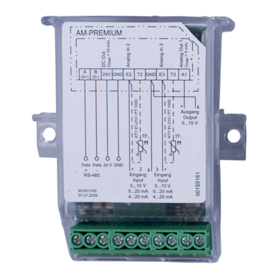
Operating Instructions AM-PREMIUM(-W) – model series Enclosure 12 Enclosure 12.1 Connection diagram AM-PREMIUM(-W) (D+) (D-) Ausgang Output 0...10 V TF.. TF.. MODBUS 24 V (RS-485) MOSI11K0 Eingang Eingang 24.04.2013 Input Input 0...10 V (R > 100 kΩ) 0...20 mA (R = 250 Ω) -
Page 89: Index
Operating Instructions AM-PREMIUM(-W) – model series 12.2 Index address output voltage 62, 67 Average calculation outputs 0 - 10 V Base setup P-component pin code PIN input PIN protection characteristic curve PT1000 clock frequency current increase Rampdown time 60, 64, 68... -
Page 90: Manufacturer Reference
Operating Instructions AM-PREMIUM(-W) – model series Index 12.3 Manufacturer reference Our products are manufactured in accordance with the relevant international regulations. If you have any questions concerning the use of our products or plan special uses, please contact: ZIEHL-ABEGG SE Heinz-Ziehl-Straße...
Need help?
Do you have a question about the AM-PREMIUM and is the answer not in the manual?
Questions and answers