Table of Contents

Related Manuals for ZIEHL-ABEGG UNIcon MODBUS Master


Summary of Contents for ZIEHL-ABEGG UNIcon MODBUS Master
- Page 1 UNIcon MODBUS Master CPE-300AV Control module with integrated pressure sensor e.g. for central extraction systems Operating Instructions Keep for reference! Software version: from version 11.16 L-BAL-E250-GB 1517 Index 002 Part.-No.
-
Page 2: Table Of Contents
Operating Instructions UNIcon MODBUS Master – model series CPE-300AV Content General notes ............. - Page 3 Operating Instructions UNIcon MODBUS Master – model series CPE-300AV Example for programming mode 4.01 in “Base setup ” ..... . .
- Page 4 Operating Instructions UNIcon MODBUS Master – model series CPE-300AV 9.8.1 Timerfunction ..........
-
Page 5: General Notes
We do not accept any liability for possible errors or omissions in the information contained in data, illustrations or drawings provided. ZIEHL-ABEGG SE is not liable for damage due to misuse, incorrect use, improper use or as a consequence of unauthorized repairs or modifications. -
Page 6: Explanations Of Symbols
Operating Instructions UNIcon MODBUS Master – model series CPE-300AV Safety instructions Explanations of symbols Safety instructions are highlighted with warning triangles and are depicted according to the degree of hazard as follows. Attention! General hazardous area. Death or severe injury or significant property damage can occur if the... -
Page 7: Work On The Device
Use only genuine spare parts / genuine wearing parts / genuine accessories from ZIEHL-ABEGG.Th- ese parts were specifically designed for the device. There is no guarantee that parts from non-original sources are designed and manufactured in correspondence with load and safety requirements. -
Page 8: Product Overview
Operating Instructions UNIcon MODBUS Master – model series CPE-300AV Product overview 3 Product overview Operational area Control module with integrated pressure sensor e. g. for central extraction systems. In connection with an external temperature sensor outside temperature compensation is possible. -
Page 9: Connection Pressure Measuring Tube
Operating Instructions UNIcon MODBUS Master – model series CPE-300AV Electrical installation Connection pressure measuring tube Depending on the tube diamater cut the cable entries and bring in measuring tubes into the device. Connection of the tubes directly to the internal pressure sensor. -
Page 10: Emc-Compatible Installation Of Control Lines
Operating Instructions UNIcon MODBUS Master – model series CPE-300AV Electrical installation • The required protective earth connection is established using screws between the housing parts in metal terminal space covers and housing casings. Commissioning is only permissible after these screws have been properly attached! •... -
Page 11: Control Outputs 0 - 10 V (A1, A2)
Operating Instructions UNIcon MODBUS Master – model series CPE-300AV Electrical installation Control outputs 0 - 10 V (A1, A2) The analogue outputs can be used to activate a speed controller with 0 - 10 V input for example. Fans with integrated controller and 0 - 10 V input can be activated directly. -
Page 12: Relay Outputs (K1, K2)
Operating Instructions UNIcon MODBUS Master – model series CPE-300AV Electrical installation Relay outputs (K1, K2) Various functions can be allocated to the relay outputs “K1” and “K2” ( IO Setup: function and inverting relais outputs). Max. contact rating technical data and connection diagram. -
Page 13: Addressing Member Modbus Master Interface
Operating Instructions UNIcon MODBUS Master – model series CPE-300AV Electrical installation • Except for the data link “A (D+)”, “B (D-)”, the “ID1 - ID2” (automatic addressing for MODBUS Master) and the “GND” connection, no further cable cores of the data line may be used. - Page 14 Operating Instructions UNIcon MODBUS Master – model series CPE-300AV Electrical installation Networking with telephone wire MODBUS Master MODBUS Slave MODBUS Slave 3...32 MODBUS MODBUS MODBUS MODBUS (RS-485) (RS-485) (RS-485) (RS-485) (D+) (D-) (D+) (D-) (D+) (D-) (D+) (D-) 13.03.2013 v_modbus_master_autoadr.vsd...
-
Page 15: Usb-Interface
Operating Instructions UNIcon MODBUS Master – model series CPE-300AV Select operation mode 5.10 USB-interface Over the USB interface if necessary a software update can be made. For this a consultation with the manufacturer is necessary. For communication with a PC (Virtual COMM Port) we make the necessary programs available on request. -
Page 16: Operation With A Second Control Circuit
Operating Instructions UNIcon MODBUS Master – model series CPE-300AV Select operation mode Operation with a second control circuit The function for control circuit 1 is determined by selection of the mode. This influences the output with function A second control circuit with separate actual value measuring and separate output can be activated additionally if required. - Page 17 Operating Instructions UNIcon MODBUS Master – model series CPE-300AV Select operation mode Setting 1. Min. Speed Minimal Speed for control circuit 1 Setting range: 0 rpm... “1. Max. Speed” Factory setting: 0 % 1. Min. Speed Setting 1. Max. Speed Maximal Speed for control circuit 1 Setting range: 100 %...
-
Page 18: External Setpoint / External Speed Setting In Manual Operation
Operating Instructions UNIcon MODBUS Master – model series CPE-300AV Start-up 2. Setpoint 1/2 for control circuit 2: Switch over “Setpoint 1” / “Setpoint 2” (9D) for control circuit 2: Switch over Setpoint 1/2 and Pband 1/2 2.Setp+Pband1/2 When programming this function, “Setting” additionally lists the parameter: “2.Pband 2 for (16D) control circuit 2.”... - Page 19 Operating Instructions UNIcon MODBUS Master – model series CPE-300AV Start-up Procedure for commissioning 1. Turn on mains voltage – Display: (Function of display controls and menu) 2. Switch over between “Info” and “Main menu” with the “Esc” key combination 3. Menu group: Start –...
- Page 20 Operating Instructions UNIcon MODBUS Master – model series CPE-300AV Start-up Excerpt from the menu table Start PIN input - - - - - - - - - - - - - - - - - - - - Language US units...
-
Page 21: Controls And Menu
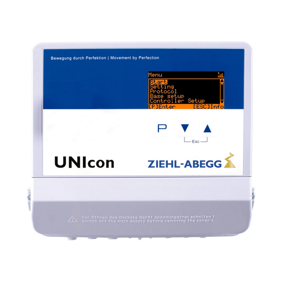
Operating Instructions UNIcon MODBUS Master – model series CPE-300AV Controls and Menu 8 Controls and Menu Multipurpose LC display and keyboard 6 7 8 9 10 Main menu 20.08.2014 v_display_erkl_cxe_modbus_master.vsd Actual value display 1. Status bar Display after line voltage is switched on or after 2. -
Page 22: Menu Operation
Operating Instructions UNIcon MODBUS Master – model series CPE-300AV Controls and Menu Menu operation Display after turning on the mains voltage Main menu Info description for menu language English = “GB” (de- Start livery status). Setting 0.0 Pa Switch over between “Info” * and “Main menu” with... -
Page 23: Menu Structure
Operating Instructions UNIcon MODBUS Master – model series CPE-300AV Controls and Menu Menu structure PIN 0010 User ← ← ← ← → → → → Service ▼ ▼ ▼ ▼ Main menu ▼ Info Main menu Main menu Main menu Main menu ▲... -
Page 24: Overview Menu Groups
Operating Instructions UNIcon MODBUS Master – model series CPE-300AV Controls and Menu Overview menu groups Possible settings Main menu Display measured actual values, selected setpoints, modulation, etc. Info Settings cannot be made in this menu group. PIN input for reset to initial settings and to protect settings. -
Page 25: Programming
Operating Instructions UNIcon MODBUS Master – model series CPE-300AV Programming 9 Programming This chapter lists some operating modes which cannot be set for the present device type! Display in SI units or Imperial units (US) The following description is for display in SI units (factory setting). The appropriate conversion factors must be observed when switching over to Imperial units (US) ( menu group Start / US Units). -
Page 26: Setting For Operation Modes 4.01
Operating Instructions UNIcon MODBUS Master – model series CPE-300AV Programming Base setup E2 Function The second signal input is not activated at the factory for modes with one sensor. The function is automatically jointly programmed in operating modes using two sen- sors. - Page 27 Operating Instructions UNIcon MODBUS Master – model series CPE-300AV Programming Setting Min. Speed Setting range: 0... “Max. Speed” Factory setting: 0 % Min. Speed Setting Max. Speed Setting range: 100 %... “Min. Speed” Factory setting: 100 % 100 % Max. Speed...
-
Page 28: Air Volume Control
Operating Instructions UNIcon MODBUS Master – model series CPE-300AV Programming Setting Min. Setpoint Minimum pressure for very low outside temperature Setting range: in measuring range of sensor 70.0 Pa Factory setting: 70 Pa Min. Setpoint Air volume control 5.01 9.2.1 Base setup 5.01... -
Page 29: Settings For Operation Modes 5.01
Operating Instructions UNIcon MODBUS Master – model series CPE-300AV Programming Base setup E2 Function The second signal input is not activated at the factory for modes with one sensor. The function is automatically jointly programmed in operating modes using two sen- sors. -
Page 30: Menu Group Start
Operating Instructions UNIcon MODBUS Master – model series CPE-300AV Programming Setting Manual mode “OFF” = automatic control as function of the set parameters (Factory setting) “ON” = automatic control without function, speed setting in menu “Speed manual” Manual mode Setting Speed manual Manual speed setting without influence by the external signal. -
Page 31: Menu Group Info
Operating Instructions UNIcon MODBUS Master – model series CPE-300AV Programming US Einheiten The display can be switched between SI units and imperial (US) units =>US units ON. SI units (factory setting): °C, bar, Pa, m /h, K-Factor, m/s US Einheiten Imperial (US) units: °F , psi, in.wg, cfm, K-Faktor US, ft/s... -
Page 32: Controller Setup
Operating Instructions UNIcon MODBUS Master – model series CPE-300AV Programming Info Level modulation control output. In addition to the bar chart, the level of the output voltage is indicated. Control The modulation for each control circuit is displayed in operation with two control circuits: “1. -
Page 33: Pin Protection Activate, Pin 1234
Operating Instructions UNIcon MODBUS Master – model series CPE-300AV Programming 9.5.2 PIN protection activate, PIN 1234 The “Settings” menu for the user’s basic settings (Setpoint, default value, min, max ..) Controller Setup are freely accessible when using the factory settings (i.e. without “PIN”). -
Page 34: Limit
Operating Instructions UNIcon MODBUS Master – model series CPE-300AV Programming 9.5.5 Limit Controller Setup After allocation of a digital input ( IO Setup) an adjustable limitation of the modulation can be activated via a digital input (“D1”, “D2”, ..). Display as long as no allocation has been carried out in “IO Setup”:... -
Page 35: Reverse Action Of The Control Function
Operating Instructions UNIcon MODBUS Master – model series CPE-300AV Programming 9.5.7 Reverse action of the control function Controller Setup For the effect of the regulation there are two functions: • “Val>Set=n+” increasing Fanlevel for increasing actual value over Setpoint. •... - Page 36 Operating Instructions UNIcon MODBUS Master – model series CPE-300AV Programming Controller Setup P-component = reaction time Setting range: 0 - 200 % smaller = more slowly 50 % bigger = faster Controller Setup I-component = accuracy, correction time Setting range: 0 - 200 %...
-
Page 37: Group Control
Operating Instructions UNIcon MODBUS Master – model series CPE-300AV Programming 9.5.9 Group control Fan groups can be activated by the analogue outputs “A1” and “A2”, the relay outputs “K1” and “K2” or by the RS-485 interface for MODBUS RTU. Controller Setup... -
Page 38: Variant "0": One Controlled Group And Up To Three Switched Groups
Operating Instructions UNIcon MODBUS Master – model series CPE-300AV Programming 9.5.9.1 Variant “0”: One controlled group and up to three switched groups The programming described below applies equally for group control by analogue outputs, relay outputs and MODBUS. For group control by the analogue outputs “A1” / “A2” and the relay outputs “K1” and “K2”, the available outputs must be observed in the selection of the version (combinations are possible). - Page 39 Operating Instructions UNIcon MODBUS Master – model series CPE-300AV Programming Controller Setup OFF Value Group4 Switch-off value for group4 Setting range: 0 - 100 % 80 % Factory setting: 80 % * OFF Value Group4 Controller Setup nmin at Group4...
-
Page 40: Version "1": Two Controlled Groups
Operating Instructions UNIcon MODBUS Master – model series CPE-300AV Programming Controller Setup Group 2 ON value Switch-on value for Group2 Setting range: 0 - 100 % 50 % Factory setting: 50 % * Group 2 ON value Controller Setup OFF Value Group2... -
Page 41: Offset Control Signal
Operating Instructions UNIcon MODBUS Master – model series CPE-300AV Programming RCD Residual-current-operated protective device 9.5.11 Offset control signal Controller Setup Offset control sig. 1 If required, the characteristic of the control signal for control circuit 1 can be adjusted. To activate this function, re-program the output with function to function IO Setup. -
Page 42: Data On The Total Control Deviation
Operating Instructions UNIcon MODBUS Master – model series CPE-300AV Programming Controller 1 Comparator Sensor 2 Cout Controller 2 Sensor 1 Cout = C1 @ C1 > C2 Cout = C2 @ C2 > C1 13.03.2015 v_cxe_comparator_c1_c2.vsd 9.5.13 Data on the total control deviation The total control deviation is comprised of the sum of the control deviations for performance quantities and work quantities combined and refers to the specified areas. - Page 43 Operating Instructions UNIcon MODBUS Master – model series CPE-300AV Programming Inverting of the output voltage is possible with the settings “A1 Inverting” / “A2 IO Setup Inverting”. Factory setting: Inverting = “OFF” A1 Inverting Function Description no function Constant voltage 10 V...
-
Page 44: Digital Inputs "D1" / "D2
Operating Instructions UNIcon MODBUS Master – model series CPE-300AV Programming 9.6.2 Digital inputs “D1” / “D2” 9.6.2.1 Menu overview IO Setup Possible functions for D1 following table. D1 Function IO Setup To invert the function, switch to “ON” (display - - - - as long as no function is allocated for D1). -
Page 45: Enable On/Off Function | 1D
Operating Instructions UNIcon MODBUS Master – model series CPE-300AV Programming Switch over “automatic control” / “Speed manual” Control/Manual Possible only for operation with one control circuit! (7D) Switch over control function (e.g. “heating” / “cooling”) Heating/Cooling (8D) Complete re-start of the device... -
Page 46: External Message, Function | 2D
Operating Instructions UNIcon MODBUS Master – model series CPE-300AV Programming 9.6.2.3 External message, Function Connecting an external alarm indication (via floating contact). The device continues to work un- changed during an external indication to the digital input; the alarm symbol appears in the display. -
Page 47: Output Control Circuit 2 Additional To "A2" On "A1", Function
Operating Instructions UNIcon MODBUS Master – model series CPE-300AV Programming 9.6.2.6 Output control circuit 2 additional to “A2” on “A1”, function The output for control circuit 2 is set additionally to “A2” to “A1” (regardless of the programmed function ). Control circuit 1 has no output for the duration of the switching. -
Page 48: Intern / Extern Function | 6D
Operating Instructions UNIcon MODBUS Master – model series CPE-300AV Programming Operation with “Setpoint2” is signalized by the moon symbol for reduced operation. Info 28.7 °C E1 Actual 9.6.2.8 Intern / Extern Function For Mode Speed controller 1.01 : Switch over “Set Intern” / “Set external ”... -
Page 49: Reverse Action Of Control Function
Operating Instructions UNIcon MODBUS Master – model series CPE-300AV Programming • “D1 Inverting” “OFF” Automatic control at opened contact / manual operation at closed contact. - - - - - - - - - - • “D1 Inverting” “ON” : Automatic control at closed contact / manual operation at opened contact. -
Page 50: Setting Max. Speed On / Off Function
Operating Instructions UNIcon MODBUS Master – model series CPE-300AV Programming 9.6.2.12 Setting Max. Speed ON / OFF function The value for “Max Speed” adjusted in menu “Settings”, is activated over a digital input. I.e. the unit works independently of the controller function firm with this value. -
Page 51: Switch Over Setpoint 1/2 And Pband 1/2 For Control Circuit 2
Operating Instructions UNIcon MODBUS Master – model series CPE-300AV Programming 9.6.2.14 Switch over Setpoint 1/2 and Pband 1/2 for control circuit 2 Switch over between “2.Setpoint 1” / “2.Setpoint 2” and “2.Pband 1” / “2.Pband 2” (only for operation with second control circuit possible). -
Page 52: Configuration Of Analog Inputs "E1"And "E2
Operating Instructions UNIcon MODBUS Master – model series CPE-300AV Programming With the “Override Timer” contact the limitation (from 6:00 - 10:00 am) activated by the timer can be cancelled for an adjustable period “Override Time” ( timer / timer function overwritten: Override Status = OFF) To activate the limitation outside the programmed time (10:01 - 5:59 am) =>... - Page 53 Operating Instructions UNIcon MODBUS Master – model series CPE-300AV Programming Example for Mode “1.01” with speed setting signal 0 - 10 V Modus 1 Modus 1 n [%] Example: “E1 min.” = 20 % The controller begins only at approx. 20% higher signal with minimal modulation.
-
Page 54: Inverting Analog Inputs "E1" / "E2
Operating Instructions UNIcon MODBUS Master – model series CPE-300AV Programming 9.6.3.2 Inverting analog inputs “E1” / “E2” After programming the signal or sensor type, an inversion of the inputs can be carried out. IO Setup Factory setting for Inverting inputs = “OFF” (if input activated) (signal: 0 - 10 V, 0 - 20 mA, 4 - 20 mA). -
Page 55: Function And Inverting For Relay Outputs "K1" And "K2
Operating Instructions UNIcon MODBUS Master – model series CPE-300AV Programming 9.6.4 Function and inverting for relay outputs “K1” and “K2” IO Setup Various functions can be allocated to the relay outputs “K1” and “K2”. In case of the same function allocation for “K1” and “K2”, these work parallel. -
Page 56: Com2 Function
Operating Instructions UNIcon MODBUS Master – model series CPE-300AV Programming 1 = energized, terminals 11-14 bridged 0 = de-energized, terminals 11-12 bridged 1 = energized, terminals 21-24 bridged 11.05.2007 0 = de-energized, terminals 21-22 bridged v_relais_k1_k2.vsd Function Controller status K1/ K2... -
Page 57: Limit Indication Depending On Setting Or Sensor Signal
Operating Instructions UNIcon MODBUS Master – model series CPE-300AV Programming If the modulation exceeds the set “Level max” value, this is reported until the set value Limits “Level min” has been undercut. The indication is delayed by the time set in “Display delay”. - Page 58 Operating Instructions UNIcon MODBUS Master – model series CPE-300AV Programming Filter Message Like function with fault message “Filter” (4L) In the IO setup, a separate relay can be allocated independent of these settings. Limits Both values for E1 (“E1 min” and “E1 max”) can be set independent of each other and act on a relay together if correspondingly programmed.
- Page 59 Operating Instructions UNIcon MODBUS Master – model series CPE-300AV Programming Only for active Setpoint of control circuit 1! Display for operation with two control circuits: 1.Offset function, 1.Offset 1, 1.Offset 2, 1.Offset hyst., 1.Offset Delay Limits Following functions can be allocated to the limit indication.
-
Page 60: Timer
Operating Instructions UNIcon MODBUS Master – model series CPE-300AV Programming Offset 1 for alarm during exceeding Offset 2 for alarm during undercutting OFF = 20°C - 2 K = 18 °C OFF = 15°C + 2 K = 17 °C ON = 15°C + 5 K = 20 °C... -
Page 61: Setting Of Time And Date
Operating Instructions UNIcon MODBUS Master – model series CPE-300AV Programming Function Description * Timer ON = (@ Timer Invert. = OFF) Switch over control function (e.g. “heating” / “cooling”) Heating/Cooling Reversal standard (8D) 1.Setp+Pband1/2 for control circuit 1: Switch over Setpoint 1/2 and Pband 1/1... -
Page 62: Automatic Summer Time
Operating Instructions UNIcon MODBUS Master – model series CPE-300AV Programming 9.8.3 Automatic summer time The summertime automatic is factory set to “OFF”, i.e. switched off. When the summertime automatic is activated the device automatically switches between daylight saving time and wintertime. -
Page 63: Inverting Timer Function
Operating Instructions UNIcon MODBUS Master – model series CPE-300AV Programming Factory setting without preprogrammed switching times Mon-Sun Mon-Fri Sat-Sun - -:- - - -:- - - -:- - - -:- - - -:- - - -:- - - -:- -... -
Page 64: Overwrite Timer Function
Operating Instructions UNIcon MODBUS Master – model series CPE-300AV Programming 9.8.6 Overwrite timer function The timer output can be overwritten for a settable time with a selectable status if required. Activation is by a digital input ( IO Setup function Application: Exceptions from the normal timing operation, e.g. -
Page 65: Modbus Master
Operating Instructions UNIcon MODBUS Master – model series CPE-300AV Programming MODBUS Slave UART Mode Setting transfer format Valid values: 8O1, 8N1, 8E1 Factory setting: 8E1 UART Mode 9.10 MODBUS Master Addressing of the members that are activated via the MODBUS Master interface. -
Page 66: Manual Addressing
Operating Instructions UNIcon MODBUS Master – model series CPE-300AV Programming Addressing Found: 0 In progress [P] Repeat [ESC] Cancel MODBUS Master The found members count is displayed at the end of automatic addressing. Press the P-key again to repeat the addressing. -
Page 67: Member Mobus Master
Operating Instructions UNIcon MODBUS Master – model series CPE-300AV Programming 9.11 Member MOBUS Master After addressing, (manual or automatic) the members are then listed to the “MODBUS Master” menu group. Main menu The function for activation by MODBUS is displayed after the address of the member. -
Page 68: Menu Tables
Operating Instructions UNIcon MODBUS Master – model series CPE-300AV Menu tables Menu tables 10.1 Menues of operating modes Mode User Setting 4.01 4.02 4.03 5.01 Parameter Factory setting Info E1 Actual 88.7 Pa 88.7 Pa 88.7 Pa 712 m E2 Actual - - - - - 21.0 °C... - Page 69 Operating Instructions UNIcon MODBUS Master – model series CPE-300AV Menu tables Mode User Setting 4.01 4.02 4.03 5.01 Parameter Factory setting Base setup Mode 4.01 4.02 4.03 5.01 E1 Analog In INT300 INT300 INT300 INT300 E1 K-Faktor E1 Unit - - - - -...
- Page 70 Operating Instructions UNIcon MODBUS Master – model series CPE-300AV Menu tables Mode User Setting 4.01 4.02 4.03 5.01 Parameter Factory setting Offset control sig. 1 Selection amplifier IO Setup A1 Function A1 min. 0.0 V 0.0 V 0.0 V 0.0 V A1 max.
- Page 71 Operating Instructions UNIcon MODBUS Master – model series CPE-300AV Menu tables Mode User Setting 4.01 4.02 4.03 5.01 Parameter Factory setting Offset 2 - - - - - - - - - - - - - - - - - - - - 1.Offset 2...
-
Page 72: Possible Allocation Of The Ios, Pins
Operating Instructions UNIcon MODBUS Master – model series CPE-300AV Menu tables 10.2 Possible allocation of the IOs, PINs Units for analog inputs E1 and E2 The following units can be set for programmed sensors with free measuring range (0 - 10 V, 0 - 20 mA, 4 - 20 mA). - Page 73 Operating Instructions UNIcon MODBUS Master – model series CPE-300AV Menu tables Switch over “Intern” / “Extern” Setpoint int./ext. Possible only for operation with one control circuit! (6D) Switch over “automatic control” / “Speed manual” Control/Manual Possible only for operation with one control circuit! (7D) Switch over control function (e.g.
- Page 74 Operating Instructions UNIcon MODBUS Master – model series CPE-300AV Menu tables Function Description Function E2 Cold-Temperature Pressure control condensers with input for refrigerant, pre-settings, sensor selection (10E) and input for refrigerant corresponding to mode 3.02 Air Pressure Pressure control air conditioning, pre-settings and sensor selection correspond to...
-
Page 75: 11 Diagnostics Menu
Operating Instructions UNIcon MODBUS Master – model series CPE-300AV Diagnostics menu PINs Function PIN 0010 Opening service menu, if PIN-protection activated PIN 1234 Opening “setting”. if “set protection” = “ON” ( Controller Setup) PIN 9090 Restore user setting PIN 9091 Save user setting (corresponds function “Save user setup”... -
Page 76: 12 Protocol
Operating Instructions UNIcon MODBUS Master – model series CPE-300AV Protocol 4.0 V E2 - Voltage Diagnostic Status digital input 1 (Digital In 1) ON = terminals D1 - 24V bridged ↔ OFF = terminals D1 - 24V not bridged Diagnostic Status digital input 2 (Digital In 2) ON = terminals D2 - 24V bridged ↔... -
Page 77: Messages And Trouble Shooting
Operating Instructions UNIcon MODBUS Master – model series CPE-300AV Protocol Cause of the message no longer exists. Line Fault Runtime Controller 000493:04:59 Example: Previous line failure on a member Protocol 2/100 Previous line failure on a member connected via the MODBUS interface. - Page 78 Operating Instructions UNIcon MODBUS Master – model series CPE-300AV Protocol Display Cause Reaction of Controller Relais switches * Opera- Failure Adjustment tion fault in Eprom Works with defaults. Factory setting fault EEP damaged Works with defaults. EEP error EEP data incorrectly controller runs with the read settings.
- Page 79 Operating Instructions UNIcon MODBUS Master – model series CPE-300AV Protocol Display Cause Reaction of Controller Relais switches * Opera- Failure Adjustment tion Device continues working unchanged. Limit indication maximum Limit indication depending on set- Signal actual value above Lmt E2 max.
-
Page 80: 13 Enclosure
Operating Instructions UNIcon MODBUS Master – model series CPE-300AV Enclosure 13 Enclosure 13.1 Technical data Type Part-No. Line voltage Weight CPE-300AV 320061 0.97 kg 1 ~ 230 V (-15 % to +10 %), 50/60 Hz Input resistance for sensor signal (E2) for 0 - 10 V input: R >... -
Page 81: Connection Diagram
Operating Instructions UNIcon MODBUS Master – model series CPE-300AV Enclosure 13.2 Connection diagram CPE-300AV Drucksensor Kontaktbelastung Pressure sensor Contact rating Digital 24 V DC Analog Analog 0...300 Pa max. AC 250 V 2 A In 1/2 Out 1/2 In 1/2... -
Page 82: Index
Operating Instructions UNIcon MODBUS Master – model series CPE-300AV 13.4 Index addition, P-component addressed pin code automatic addressing 13, 66 PIN input PIN protection 32-33 Protocol PT1000 Base setup bus mode Relay outputs COM2 control cable control circuit 1 second control circuit... -
Page 83: Manufacturer Reference
Operating Instructions UNIcon MODBUS Master – model series CPE-300AV Index 13.5 Manufacturer reference Our products are manufactured in accordance with the relevant international regulations. If you have any questions concerning the use of our products or plan special uses, please contact: ZIEHL-ABEGG SE Heinz-Ziehl-Straße...
Need help?
Do you have a question about the UNIcon MODBUS Master and is the answer not in the manual?
Questions and answers