
Related Manuals for ZIEHL-ABEGG Brake Module


Summary of Contents for ZIEHL-ABEGG Brake Module
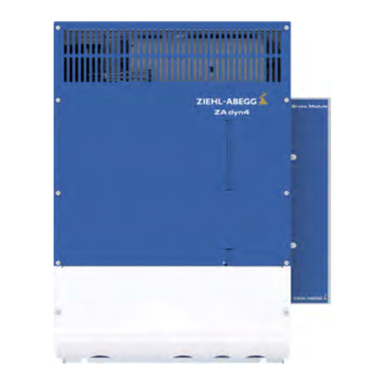
- Page 1 Brake Module Brake activation for ZAdyn4C Original operating instructions Store for future use ! R-TBA13_01-GB 1630 Art.-Nr. 00163414-GB...
-
Page 2: Table Of Contents
Original operating instructions Brake Module Content General information ........ - Page 3 Enclosure ..........Technical Data Brake Module ......
-
Page 4: General Information
1 General information 1.1 Structure of the operating instructions These Operating Instructions serve for safe working on and with the Brake Module for the ZAdyn4C. It contains safety instructions that must be complied with as well as information that is required for failure-free operation of the device. -
Page 5: Safety Instructions
2.2 Intended use The Brake Module is an external auxiliary unit to the ZAdyn4C for activating the motor brakes with contactors. The device is not designed for any other use than those listed here – this is considered as improper use. -
Page 6: Product Safety
Original operating instructions Brake Module Safety instructions 2.4 Product safety The device conforms to the state of the art at the time of delivery and is fundamentally considered to be reliable. The device and its accessories must only be used in a flawless condition and installed and operated with compliance to the operating instructions. -
Page 7: Working On Device/Hazards Through Residual Voltage
ZIEHL-ABEGG SE.These parts were specifically designed for the device. There is no guarantee that parts from non-original sources are designed and manufactured in correspondence with load and safety requirements. Parts and special equipment not supplied by the ZIEHL-ABEGG SE are not approved for use. 2.9 Operator’s obligation of diligence... -
Page 8: Employment Of External Personnel
You must monitor their working methods in order to intervene in good time if necessary. 3 Product overview 3.1 Application The Brake Module is an auxiliary unit to the ZAdyn4C for activating the motor brakes. 3.2 Functional description Activation of motor brake •... -
Page 9: Mechanical Installation
Mechanical installation 4 Mechanical installation 4.1 General notes The Brake Module is mounted on the side of the ZAdyn4C Danger! The following points must be complied with during the mechanical installation to avoid causing a defect in the device due to assembly errors or environmental influences: Before installation •... -
Page 10: Assembly On The Zadyn4C 011-032
Original operating instructions Brake Module Mechanical installation 4.2 Assembly on the ZAdyn4C 011-032 Push the mounting plate into the top groove of the ZAdyn4C " 1 top groove 2 mounting plate Screw the M5 screws with washers two turns into the mounting plate. - Page 11 Mechanical installation " Tighten the M5 screws. Hook the Brake Module into the top hooks on the fastening plate (6) with the openings " at the side (7). Press the Brake Module down carefully until it is touching. 6 top hook of the fastening plate 7 openings of the Brake Module Remove the cover of the Brake Module.
-
Page 12: Assembly On The Zadyn4C 040-074
Original operating instructions Brake Module Mechanical installation " Mount the cover of the Brake Module. 4.3 Assembly on the ZAdyn4C 040-074 Insert the hook (1) of the fastening plate in the openings (2) on the right side of the "... - Page 13 Mechanical installation " Hook the Brake Module into the top hooks on the fastening plate (7) with the openings at the side (8). Press the Brake Module down carefully until it is touching. 7 top hook of the fastening plate 8 openings of the Brake Module Remove the cover of the Brake Module.
-
Page 14: Dimensions / Minimum Clearances
Brake Module Mechanical installation 4.4 Dimensions / minimum clearances ZDSB01M0 77.5 Brake Module dimensions in mm 377.5 377.5 ZAdyn4C 011-032 and ZAdyn4C 011-032 and Brake Module dimensions in mm Brake Module minimum distances in mm R-TBA13_01-GB 1630 Part.-No. 00163414-GB 14/32... - Page 15 Original operating instructions Brake Module Mechanical installation ZDSB01M0 ZAdyn4C 040-074 and ZAdyn4C 040-074 and Brake Module dimensions in mm Brake Module minimum distances in mm R-TBA13_01-GB 1630 Part.-No. 00163414-GB 15/32...
-
Page 16: Electrical Installation
Wait at least 3 minutes before working on the device Danger! Operating the Brake Module with the housing cover removed is prohibited because energized, exposed parts are present inside the device. Disregarding this regulation can lead to severe personal injury. -
Page 17: Terminal Positions
Original operating instructions Brake Module Electrical installation 5.2 Terminal positions Terminal positions 1 X-BA activation of brakes 2 X-K1 monitoring of brake contactors 3 X-K2 Voltage supply brakes / Break test, emergency rescue 4 X-SC activation of STO relays safety circuit R-TBA13_01-GB 1630 Part.-No. -
Page 18: Strain Relief
1 recesses for strain relief 5.4 Protective earth connection The protective earth is already pre-assembled on the Brake Module. Connect the protective earth of the Brake Module to the protective earth connection of " the ZAdyn4C. PE conductor connection ZAdyn4C 040-074... -
Page 19: Connection Motor Brake
5.6.1 Activation of the brake contactor K3. The brake contactor K3 is activated by a relay-output of the ZAdyn4C. The cable L-SL-...-HX-BM/SBM-MB is already connected to the Brake Module. Connect this cable to the output with the function "MB_Brake" at the terminal X-OUT "... -
Page 20: Connection Control System
The ralays K1 and K2 are activated depending on the safety circuit. Connect the safety circuit to the terminal X-SC. " ZIEHL-ABEGG SE offers the pre-fabricated cable L-SL-...-HX-BM/SBM-SC. 5.7.2 Contactor control " Connect the contactor monitoring to the terminal X-K1. -
Page 21: Process
Original operating instructions Brake Module Electrical installation For further information about the brake release monitoring by the ZAdyn4C, see the ZAdyn4C Operating Instructions, chapter "Electrical Installation/Brakes". 5.9 Process Sicherheitskreis K1+K2 Eingänge STO_A STO_B Ausgänge K1, K2 STO relay K4 Brake contactor... -
Page 22: Circuit Suggestions Brake Module And Zadyn4C
Original operating instructions Brake Module Electrical installation 5.10 Circuit suggestions Brake Module and ZAdyn4C 5.10.1 Actuation for brakes without over excitation 1 Power supply brakes 2 Power supply contactor / Safety circuit 3 Contactor control 4 manual brake release A... -
Page 23: Actuation For Brakes With Over Excitation
Original operating instructions Brake Module Electrical installation 5.10.2 Actuation for brakes with over excitation 1 Power supply brakes 2 Power supply contactor / Safety circuit 3 Contactor control 4 manual brake release A 5 manual brake release B 6 Emergency operation / two-circuit test... -
Page 24: Enclosure
Original operating instructions Brake Module Enclosure 6 Enclosure 6.1 Technical Data Brake Module 4-230-207 4-110-207 4-230-103 4-110-103 Electrical data Mains connection voltage max. 253 100-250 brake, U~ Mains frequency [Hz] 50 / 60 (±1,5 Hz) Holding 0,9 x U~ 0,45 x U~... -
Page 25: Type Designation
Original operating instructions Brake Module Enclosure Ambient conditions oper- [°C] 0 ... 45 ation Relative humidity 90 / condensation prohibited Installation height [m über bis 2000 m Storage and shipping [°C] -20...+60 °C temperature Degree of soiling (in acc. with DIN EN 61800-5-1) -
Page 26: Part No
Original operating instructions Brake Module Enclosure 6.3 Part no. Brake Module BM 4-230/207 357263 BM 4-230/103 357264 BM 4-110/207 357265 BM 4-110/103 357266 R-TBA13_01-GB 1630 Part.-No. 00163414-GB 26/32... -
Page 27: Eu Declaration Of Conformity
Original operating instructions Brake Module Enclosure EU declaration of conformity - Translation - (english) A-KON16_09-GB 1633 Index 002 Manufacturer: ZIEHL-ABEGG SE Heinz-Ziehl-Straße 74653 Künzelsau Germany The manufacturer shall bear sole responsibility for issuing this EU declaration of conformity. Product descrip-... - Page 28 Original operating instructions Brake Module Enclosure This declaration relates exclusively to the product in the state in which it was placed on the market, and excludes components which are added and/or operations carried out subsequently by the final user. The authorised representative for the assembly of the technical file is: Mr.
- Page 29 Original operating instructions Brake Module Enclosure R-TBA13_01-GB 1630 Part.-No. 00163414-GB 29/32...
- Page 30 Original operating instructions Brake Module Enclosure R-TBA13_01-GB 1630 Part.-No. 00163414-GB 30/32...
- Page 31 Original operating instructions Brake Module Enclosure R-TBA13_01-GB 1630 Part.-No. 00163414-GB 31/32...
- Page 32 Customer Service phone +49 7940 16-308 +49 7940 16-249 drives-service@ziehl-abegg.com Headquarters ZIEHL-ABEGG SE Heinz-Ziehl-Strasse · 74653 Künzelsau Germany phone +49 7940 16-0 · fax +49 7940 16-249 drives@ziehl-abegg.de · www.ziehl-abegg.com...
Need help?
Do you have a question about the Brake Module and is the answer not in the manual?
Questions and answers