
Related Manuals for ZIEHL-ABEGG UNIcon CPG AVC Series


Summary of Contents for ZIEHL-ABEGG UNIcon CPG AVC Series
- Page 1 english UNIcon CPG-..AVC Sensor-control module for differential pressure and volume ow Operating Instructions Keep for reference! Software version: from Version 1.00 L-BAL-E286-GB 1904 Index 004 Part.-No. 00163471...
-
Page 2: Table Of Contents
Operating Instructions UNIcon CPG-..AVC Content General notes ..........Structure of the operating instructions . - Page 3 Operating Instructions UNIcon CPG-..AVC 8.2.2 Nozzle coefficient (K-Factor) ..... . 8.2.3 Setting for operation 5.01 5.02 ....Menu group "INFO"...
-
Page 4: General Notes
Operating Instructions UNIcon CPG-..AVC General notes 1 General notes Compliance with the following instructions is mandatory to ensure the functionality and safety of the product. If the following instructions given especially but not limited for general safety, transport, storage, mounting, operating conditions, start-up, mainte- nance, repair, cleaning and disposal / recycling are not observed, the product may not operate safely and may cause a hazard to the life and limb of users and third parties. -
Page 5: Safety Instructions
Operating Instructions UNIcon CPG-..AVC Safety instructions 2 Safety instructions Attention! • Mounting, electrical connection, and start-up operation may only be carried out by an electrical specialist in accordance with electrotechnical regulations (e.g. DIN EN 50110 or DIN EN 60204)! • Persons entrusted with the planning, installation, commissioning and maintenance and servicing in connection with the device must have the corresponding qualifications and skills for these jobs. -
Page 6: Product Overview
Operating Instructions UNIcon CPG-..AVC Product overview 3 Product overview 3.1 Function Sensor-control module with differential-pressure sensors in proven ceramic-cantilever technology for climate and clean-room application. The pressure range from 0 to 6000 Pa (24 in.wg) is covered with 3 types of device. With each type four measuring ranges are programmable. -
Page 7: Mounting
Operating Instructions UNIcon CPG-..AVC Mounting 4 Mounting • Before installation remove the device from the packing and check for any possible shipping damage! • Assemble the device on a clean and stable base. Do not distort during assembly! Use the appropriate mounting devices for proper installation of the unit! •... -
Page 8: Connection Voltage Supply
Operating Instructions UNIcon CPG-..AVC Electrical installation 5.2 Connection Voltage supply Connection Voltage supply at terminals: “+U ” and “GND”. Here, it must be strictly observedt hat the mains voltage lies within the llowable olerance pecifications (see Technical data and nameplate affixed to the side). Danger due to electric current Only PELV current sources which ensure safe electrical isolation of the operating voltage in accordance with IEC/DIN EN 60204-1 must be used. -
Page 9: Digital Input (D1)
Operating Instructions UNIcon CPG-..AVC Electrical installation 5.4 Digital input (D1) Different functions can be assigned to the digital input D1(see IO SETUP). A voltage at terminals “1” and “2” (10...24 V DC) activates the programmed function (note polarity - see connection diagram). 5.5 Relay outputs “K1”... -
Page 10: Rs-485 Interface For Modbus
Operating Instructions UNIcon CPG-..AVC Electrical installation 5.6 RS-485 interface for MODBUS The device comes equipped with a RS-485 interface for networking via MODBUS. Conntection at: “A (D+)”, “B (D-)” and “GND”. MODBUS MODBUS MODBUS MODBUS (RS-485) (RS-485) (RS-485) (RS-485) (D+) (D-) (D+) (D-) - Page 11 Operating Instructions UNIcon CPG-..AVC Electrical installation Recommended wire types 1. CAT5 / CAT7 cables 2. J-Y (St) 2x2x0.6 (telephone cable) 3. AWG22 (2x2 twisted pair) Max allowed wire length 1000 m (CAT5/7 500 m). Shielding The use of shielded cables is normally not needed but offers high protection against electromagnetic interferences, especially high frequencies.
-
Page 12: Automatic Addressing
Operating Instructions UNIcon CPG-..AVC Electrical installation 5.6.1 Automatic addressing Automatic addressing can be started when the connections “ID1” and “ID2” for “Address- ing” are connected with each other additionally next to the bus connection. I. e. it is no longer necessary to address every user manually in the network. (D+) (D-) A-G-247NW... -
Page 13: Input For Outdoor Temperature Sensor
Operating Instructions UNIcon CPG-..AVC Electrical installation 5.7 Input for outdoor temperature sensor 4.02 5.02 operating modes with setpoint adjustment depending on outdoor temperature, the outdoor temperature sensor is connected at the “TF” terminals. You can connect passive temperature sensors TF... (KTY81-210) or PT1000, and the polarity is not relevant. -
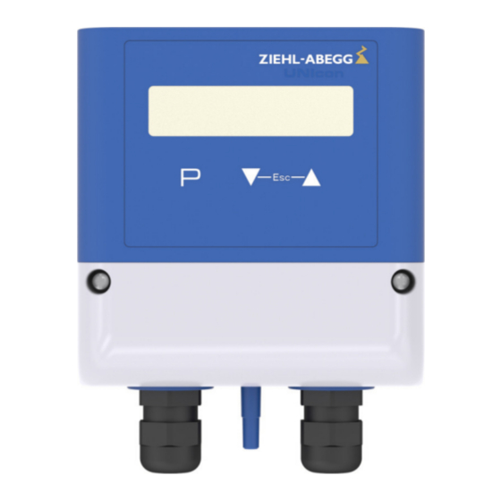
Page 14: Device Construction
Operating Instructions UNIcon CPG-..AVC Device construction 6 Device construction 6.1 Connecting elements 1 Signal relay (terminals: 13, 14) 2 Supply voltage (terminals: U , GND) 3 Output signal 0...10 V (terminals: A, GND) 4 Cable gland M16 + seal insert with two holes (5 mm) 5 "Minus"- connection in area with lower pressure 6 "Plus"- connection in area with higher pressure 7 Digital input D1 (terminals: 1, 2) -
Page 15: Modes/Start-Up
Operating Instructions UNIcon CPG-..AVC Modes/Start-up Messages on the display No enable Exceeding measuring range Moon symbol = Adjustment for Setpoint 2 active Hourerglass symbol = Timer function active External fault alarm External error Limit: Modulation Limit Uout Limit: Pressure Limit Pressure Limit: volume flow Limit AirVolume Limit: Temperature... -
Page 16: Start-Up
Operating Instructions UNIcon CPG-..AVC Modes/Start-up 7.2 Start-up Procedure 1. You must mount and connect the device in accordance with the operating instruc- tions. 2. Double check that all connections are correct. 3. The supply voltage must match the information on the rating plate. 4. -
Page 17: Programming
Operating Instructions UNIcon CPG-..AVC Programming Reprogramming Mode 4.01 5.00 in “BASE SETUP” 4.01 5.00 «4.01» «5.00» ▲ Mode Mode Mode Mode 8 Programming 8.1 Pressure sensor 4.00 and pressure control 4.01 4.02 8.1.1 Base setup 4.00 4.02 BASE SETUP 4.00 : Pressure sensor 4.01 4.01... -
Page 18: Settings For Operation
Operating Instructions UNIcon CPG-..AVC Programming Proceed as follows: 1. Pull off the pressurised hoses. “Autozero” “ON” 2. Switch function “0” 3. The display switches to the actual value display and the value displayed after zero point calibration has taken place. “0”... - Page 19 Operating Instructions UNIcon CPG-..AVC Programming Additional menu item for mode 4.02 with outside-temperature dependent target- setpoint Outside-temperature dependent target-setpoint An outside temperature compensation can be activated (sensor connection terminals [Pa] "TF-"TF") when being operated as a pres- sure control device. This function automatically changes the set and active “Setpoint 1”...
-
Page 20: Volume Sensor 5.00 And Volume Control
Operating Instructions UNIcon CPG-..AVC Programming 8.2 Volume sensor 5.00 and volume control 5.01 5.02 8.2.1 Base setup 5.00 5.02 BASE SETUP 5.00 : Volume flow sensor 5.01 5.01 : Volume flow control Mode 5.02 : Volume flow control with outdoor temperature compensation Display in SI units "metric"... -
Page 21: Nozzle Coefficient (K-Factor)
Values for Imperial units (US) 8.2.2 Nozzle coefficient (K-Factor) For the modes 5.00 5.01 the K-factors (SI-units) of the following ZIEHL-ABEGG fans can be taken from the table. For fans not listed here, ask the manufacturer for the K-factor. C-series Size ZAbluefin... -
Page 22: Setting For Operation 5.01 And
Operating Instructions UNIcon CPG-..AVC Programming C-series Size ZAbluefin Vpro-series M-series ZAvblue Cpro-series 1000 1050 1120 1250 Subject to technical changes! Maximum K-Factor depending on the measuring range of the pressure sensor Range [Pa] 1000 2000 3000 4000 6000 [in.wg] 12.0 16.0 24.0 Max. - Page 23 Operating Instructions UNIcon CPG-..AVC Programming Maximal output voltage 10.0 V Setting range: 10...0 V Max. Uout Factory setting: 10 V Additional menu item for mode 5.02 with outside-temperature dependent target- setpoint Outside-temperature dependent target-setpoint An outside temperature compensation can be activated (sensor connection terminals "TF-"TF") when being operated as a volume flow control device.
-
Page 24: Menu Group "Info
Operating Instructions UNIcon CPG-..AVC Programming 8.3 Menu group "INFO" The number of menus depends on the selected operating mode. Settings cannot be made in this menu group! INFO Mode Display 4.00 4.01 4.02 5.00 5.01 5.02 Actual value after turning on the voltage or after exiting the setting menu using the Esc key combination. -
Page 25: Menu Group "Io Setup
Operating Instructions UNIcon CPG-..AVC Programming Mode Display 4.00 4.01 4.02 5.00 5.01 5.02 0 Pa 0 Pa 0 Pa Δp (0.000 (0.000 (0.000 in.wg) in.wg) in.wg) Time Time 8:54 8:54 8:54 8:54 Software version 1.00 1.00 1.00 1.00 1.00 1.00 8.4 Menu group "IO SETUP"... -
Page 26: Analog Outputs "Ao
Operating Instructions UNIcon CPG-..AVC Programming 8.4.2 Analog outputs “AO” Menu overview Function Designation Setting of the desired function (see following table). Control sign. 2A AO1 Function Analog output A1 (terminals: A, GND) No further assignment possible, n.a. (no assignment) = No signal assigned. AO1 Signal Inverting output AO1 Inverting... - Page 27 Operating Instructions UNIcon CPG-..AVC Programming Fault indication (factory setting) Fault indic. Reports a failure, switch-off using the enable function (see digital inputs “DI”) is not reported. Report of an external failure triggered by digital output (no function in 4.00 Extern. Error. 5.00 Limit message modulation Limit modu.
-
Page 28: Digital Inputs "Di
Operating Instructions UNIcon CPG-..AVC Programming 8.4.4 Digital inputs “DI” The device has three virtual digital inputs: DI1, DI2 and DI3 (not available in 4.00 5.00 8.4.4.1 Menu overview Example for DI1 Function Designation Setting of the desired function (see following table). DI1 Function Allocation: virtuell input <=>... -
Page 29: Enable On/Off, Function | 1D
Operating Instructions UNIcon CPG-..AVC Programming 8.4.4.2 Enable ON/OFF, function Remote ON/OFF (electronic disconnection). The device can still be operated in the switched-off state after pressing the “Esc” key combination. ) does not report the switch- A programmed alarm relay (factory set “K1 function” = off. -
Page 30: External Message, Function
Operating Instructions UNIcon CPG-..AVC Programming 8.4.4.3 External message, function Connection of an external fault indication - the device continues operating with no changes after a message and “External Error” appears in the display. Message via relay “K1” depending on programmed function (see digital output “DO”). A programmed alarm relay (factory set “K1 function”... -
Page 31: Setpoint 1/2, Function | 5D
Operating Instructions UNIcon CPG-..AVC Programming 8.4.4.4 Setpoint 1/2, function Switching between control with Setpoint 1 and Setpoint 2. Setpoint 1active Setpoint 2 active The active Setpoint is indicated in the menu 100 Pa 80 Pa INFO, an active “Setpoint 2” is signalized by the Δp Δp moon symbol. -
Page 32: Menu Group "Limits
Operating Instructions UNIcon CPG-..AVC Programming 8.5 Menu group "LIMITS" 8.5.1 Limit message modulation Menu overview Function Designation OFF: no function ON: limit message active The “Limit Uout” message appears in the display if the set limit value for modulation is exceeded. The message via the relay depends on the pro- Level Fuction grammed function (see IO Setup), with the factory setting (K1 function = , not inverted) the relay is de-energised (terminals 13 - 14 disconnected). -
Page 33: Limit Message Actual Value
Operating Instructions UNIcon CPG-..AVC Programming 8.5.2 Limit message actual value Menu overview Function Designation OFF: no function ON: limit message active The values "Value min." and "Value max." can be set independently of one another. The unit depends on the selected operating mode ( ) and unit (metric / inch). -
Page 34: Limit Message Outdoor Temperature
Operating Instructions UNIcon CPG-..AVC Programming Example for limit message actual value Settings - Value Max.: 800 Pa - Value Min.: OFF Analog IN - switching hysteresis 5 % (from 100 %) 11.05.2007 50 % 100 % v_grenzwert_signal_k1_1.vsd Settings - Value Min.: 200 Pa - Value Max.: OFF Analog IN - switching hysteresis 5 % (from 100 %) -
Page 35: Timer
Operating Instructions UNIcon CPG-..AVC Programming Information Always set the value for "Temp max." higher than the value for "Temp min.". Examples for limit messages outdoor temperature Settings - Temp. Max.: 80 °C - Temp. Min.: OFF Analog IN - switching hysteresis 5 % (from 100 %) 11.05.2007 50 % 100 %... -
Page 36: Modbus Slave
Operating Instructions UNIcon CPG-..AVC Programming Menu overview Parameter Designation Time Press the P-key and set the hours with the UP / DOWN keys, press the P- 15:05 key to save. Time Now the minutes flash and can be set with the UP / DOWN keys, press the P- key to save. - Page 37 Operating Instructions UNIcon CPG-..AVC Programming Menu overview Function Designation Bus Address The device address is factory set to the highest available MODBUS address: 247. Bus Address Setting range MODBUS Address: 1 - 247. UART Baudrate Setting transfer rate 19200 Valid values: 4800, 9600, 19200, 38400, 115200 UART Baudrate Factory setting: 19200 UART Mode...
-
Page 38: Modbus Register
Operating Instructions UNIcon CPG-..AVC Programming 8.7.2 MODBUS Register 8.7.2.1 Holding register Mode Function/Setting 00 01 02 00 01 02 0 = OFF 1 = Restore factory setting (delivery status) Input MODBUS, digital control bit wise* Digital inputs DI1-3 @ Bit 15, relay K1 @ Bit 14 On register H23 Value 2 = Function 17A: Preset output voltage from analog output “AO”... - Page 39 Operating Instructions UNIcon CPG-..AVC Programming Mode Function/Setting 00 01 02 00 01 02 x Time delay limit message actual value: 0...120 (s) x Limit message outdoor temperature: 0 = OFF, 1 = ON Minimum temperature: -500 = OFF, -500...1500 -50.0...150.0 °C (-580 = OFF, -580...3020 -58.0...302.0 °F) Maximum temperature:...
-
Page 40: Input Register
Operating Instructions UNIcon CPG-..AVC Programming Information The registers HR00, HR01, HR02, HR47, HR51, HR52 and HR53 can be written as often as needed. For all other registers, write processes are limited to 10,000 (i.e. only use them for configuration purposes). Value of the bits Bit 0 Bit 1 Bit 2 Bit 3 Bit 4 Bit 5 Bit 6 Bit 7 Bit 8 Bit 9 Bit 10 Bit 11 Bit 12 Bit 13 Bit 14 Bit 15 0x8000 0x4000 0x2000 0x1000 0x0800 0x0400 0x0200 0x0100 0x0080 0x0040 0x0020 0x0010 0x0008 0x0004 0x0002 0x0001... -
Page 41: Enclosure
Operating Instructions UNIcon CPG-..AVC Enclosure 9 Enclosure 9.1 Technical data Type CPG-200AVC CPG-1000AVC CPG-6000AVC Part-No. 320075 320076 320077 Voltage supply 10...24 V DC (+20 %) Protected against reverse polarity 10 V DC 13...24 V DC Max. load output 0...10 V 0.3 mA 10 mA (short-circuit-proof) - Page 42 Operating Instructions UNIcon CPG-..AVC Enclosure Total of linearity, hysteresis and repeat- ability max. Long term stability according to +/-1.0 +/- 1.0 +/- 1.0 DIN EN 60770 Temperature coefficient typical +/- 0.2 +/- 0.2 +/- 0.2 Temperature coefficient max. +/- 0.4 +/- 0.4 +/- 0.4 Temperature coefficient sensitivity typical % /...
-
Page 43: Connection Diagram
Operating Instructions UNIcon CPG-..AVC Enclosure 9.2 Connection diagram CPG-200/1000/6000AVC Kontaktbelastung Contact rating MODBUS Slave max. AC 250 V 2 A = 4 kΩ (D+) (D-) GND A GND 1(+) 2( ) (D+) (D-) ∆p TF.. Spannungsversorgung Voltage supply 10...24 V DC (10...24 V: I = 28 mA) KTY 81-210... -
Page 44: Manufacturer Reference
- ventilation technology. phone: +49 (0) 7940 16-800 Email: fan-controls-service@ziehl-abegg.de Our worldwide contacts are available in our subsidiaries for deliveries outside of Ger- many, see www.ziehl-abegg.com. L-BAL-E286-GB 1904 Index 004 Part.-No. 00163471 44/44...
Need help?
Do you have a question about the UNIcon CPG AVC Series and is the answer not in the manual?
Questions and answers