Table of Contents
Advertisement
Quick Links
G**-SMV03EN
ORIGINAL INSTRUCTIONS
Refer to Declaration of
Conformity for relevant
Instruction Manual
Directives
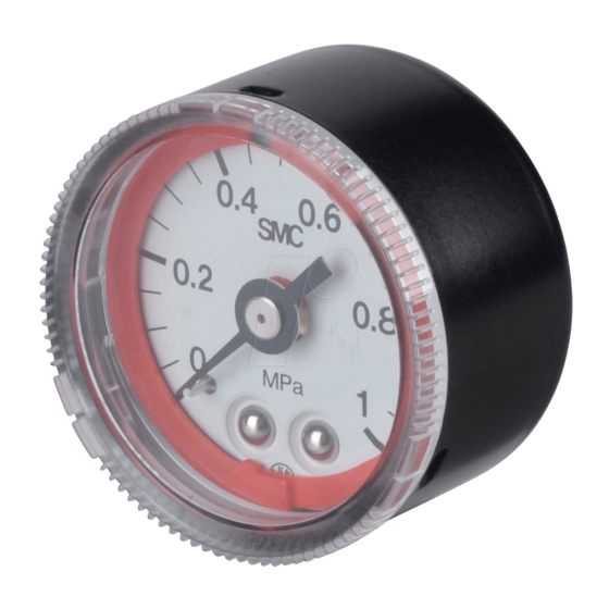
Pressure Gauge with Colour Zone Limit
Indicator
G36-L / G46-L Series
The intended use of the pressure gauge is to measure the internal
pressure of a vessel or system. The adjustable red and green zone
indicators help the user by improving visibility of the control range.
Validated according to ISO 13849, see section 2. Refer to product
catalogues for additional information.
1 Safety Instructions
These safety instructions are intended to prevent hazardous situations
and/or equipment damage. These instructions indicate the level of
potential hazard with the labels of "Caution," "Warning" or "Danger."
They are all important notes for safety and must be followed in addition
*1)
to International Standards (ISO/IEC)
, and other safety regulations.
*1)
ISO 4414: Pneumatic fluid power - - General rules relating to
systems.
ISO 4413: Hydraulic fluid power - - General rules relating to
systems.
IEC 60204-1: Safety of machinery - - Electrical equipment of
machines. (Part 1: General requirements)
ISO 10218-1: Manipulating industrial robots - - Safety. etc.
This manual contains essential information for the protection of users
and others from possible injury and/or equipment damage.
Read this manual before using the product, to ensure correct
handling, and read the manuals of related apparatus before use.
Keep this manual in a safe place for future reference.
To ensure safety of personnel and equipment the safety instructions
in this manual must be observed, along with other relevant safety
practices.
Caution indicates a hazard with a low level of risk
Caution
which, if not avoided, could result in minor or
moderate injury.
Warning indicates a hazard with a medium level
Warning
of risk which, if not avoided, could result in death
or serious injury.
Danger indicates a hazard with a high level of risk
Danger
which, if not avoided, will result in death or
serious injury.
Warning
The compatibility of the product is the responsibility of the
person who designs the equipment or decides its specifications.
Since the product specified here is used under various operating
conditions, its compatibility with specific equipment must be decided
by the person who designs the equipment or decides its
specifications based on necessary analysis and test results. The
expected performance and safety assurance of the equipment will be
the responsibility of the person who has determined its compatibility
with the product. This person should also continuously review all
specifications of the product referring to its latest catalogue
information, with a view to giving due consideration to any possibility
of equipment failure when configuring the equipment.
1 Safety Instructions - continued
Only personnel with appropriate training should operate
machinery and equipment.
The product specified here may become unsafe if handled
incorrectly.
The assembly, operation and maintenance of machines or equipment
including our products must be performed by an operator who is
appropriately trained and experienced.
Do
not
service
or
attempt
to
remove
product
machinery/equipment until safety is confirmed.
1) The inspection and maintenance of machinery/equipment should
only be performed after measures to prevent falling or runaway of the
driven objects have been confirmed.
2) When the product is to be removed, confirm that the safety
measures as mentioned above are implemented and the power from
any appropriate source is cut, and read and understand the specific
product precautions of all relevant products carefully.
3) Before machinery/equipment is restarted, take measures to
prevent unexpected operation and malfunction.
Contact SMC beforehand and take special consideration of
safety measures if the product is to be used in any of the
following conditions.
1) Conditions and environments outside of the given specifications, or
use outdoors or in a place exposed to direct sunlight.
2) Installation on equipment in conjunction with atomic energy,
railways, air navigation, space, shipping, vehicles, military, medical
treatment, combustions and recreation, or equipment in contact with
food and beverages, emergency stop circuits, clutch and brake
circuits in press applications, safety equipment or other applications
unsuitable for the standard specification described in the product
catalogue.
3) An application which could have negative effects on people,
property, or animals requiring special safety analysis outside the
scope of ISO 13849 described in this document.
4) Use in an interlock circuit, which requires the provision of double
interlock for possible failure by using a mechanical protective
function, and periodical checks to confirm proper operation.
Always ensure compliance with relevant safety laws and
standards.
All electrical work must be carried out in a safe manner by a qualified
person in compliance with applicable national regulations.
Caution
The product is provided for use in manufacturing industries.
The product herein described is basically provided for peaceful use in
manufacturing industries.
If considering using the product in other industries, consult SMC
beforehand and exchange specifications or a contract if necessary.
If anything is unclear, contact your nearest sales branch.
2 Specifications
2.1 Standard Specifications
G36-L
Model
Type
Back side thread
Note 1)
Port size
R 1/8
R 1/8, R 1/4
Note 2) Note 3)
Fluid
Air
Note 4)
Indication precision
±3%F.S. (Full span)
Case (Surface
Stainless steel (Black melamine painted)
treatment)
Polycarbonate
Polycarbonate
(Part no.: G36-00-00-3)
(Part no.: G46-00-00-3)
Material
Clear cover
Nylon
(Part no.: G36-00-00-3N)
(Part no.: G46-00-00-3N)
Stud
Brass
Bourdon tube
Brass
Weight (kg)
0.04
Max operating frequency
5 cycles / sec
Attachment:
C
Part no.: 1305104-1A
With cover ring
-
assembly
C
Part no.: 1305104-3A
1
2 Specifications - continued
Air quality required
Impact and vibration
See sections 3.1.1 and 3.2.
resistance
Note 5)
B10
Note 5)
B10
D
Standards
Complies with the basic and well-tried safety
principles of EN ISO 13849-2:2012.
Table 1
and
Note 1) When mounting a pressure gauge, use caution not to tighten
excessively. Excessive tightening will cause product to be damaged.
Use a pipe tape for sealing.
Note 2) When using other fluids, please consult with SMC for fluid
compatibility information concerning corrosive potential.
Note 3) Avoid freezing as this may cause a malfunction.
Note 4) The guaranteed temperature range is 23°C ±5 °C.
Note 5) Under SMC test conditions. The B10 figure is estimated from
SMC life tests. The B10D figure is derived from B10 using the
assumption in EN ISO 13849-1:2015 Annex C. Contact SMC for details
2.1 Model Specifications (Standard)
Pressure
Green zone setting range MPa
range MPa
Model
Note 1)
Minimum
□
0 to 0.2
0.01
G36-2-01-L
□
0 to 0.4
0.02
G36-4-01-L
□
0 to 1.0
0.05
G36-10-01-L
G46-2-01 to
0 to 0.2
0.01
□
02-L
G46-4-01 to
0 to 0.4
0.02
□
02-L
G46-10-01 to
□
0 to 1.0
0.05
02-L
Table 2
Note 1) Do not apply pressure more than the maximum display
pressure. This will cause a malfunction.
2.2 Model Specifications (Made to Order)
Pressure
Green zone setting range MPa
range MPa
(psi)
Model
Note 1)
(psi)
Minimum
□
0 to 0.2
G36-P2-01-L
-
0.01 (2)
(0 to 30)
X30
□
0 to 0.4
G36-P4-01-L
-
0.02 (4)
(0 to 60)
X30
G36-P10-01-
0 to 1.0
0.05 (10)
□
(0 to 150)
L
-X30
G46-P2-01 to
0 to 0.2
0.01 (2)
□
(0 to 30)
02-L
-X30
G46-P4-01 to
0 to 0.4
0.02 (4)
□
(0 to 60)
02-L
-X30
G46-P10-01 to
0 to 1.0
0.05 (10)
□
(0 to 150)
02-L
-X30
Table 3
G46-L
Note 1) Do not apply pressure more than the maximum display
pressure. This will cause a malfunction.
Note 2) Under the New Measurement Law, products for overseas use
only (SI unit type for use in Japan).
Caution
Special products might have specifications different from those shown
in this section. Contact SMC for specific drawings. These drawings will
give the appropriate specification details and compliance with the safety
Nylon
principles of ISO 13849, if applicable.
3 Installation
3.1 Installation
0.05
Warning
Do not install the product unless the safety instructions have been read
and understood.
3 Installation - continued
5 µm or smaller
3.1.1 Selection
Make sure that no direct impact or vibrations are applied to the body.
If operating under pressure pulsations or in high frequency
850,000 cycles
operations, please contact SMC.
1.7 million cycles
3.1.2 Mounting
During transport and installation, do not apply shock to the product,
such as by dropping doing so will affect its precision.
For the installation posture, place it perpendicular to the ground, with
the zero point on the reading of a pressure gauge facing down.
Do not install it in an area that is exposed to high temperature or
humidity, because doing so will lead to improper operation.
To screw in the pressure gauge, make sure to turn the gauge by
placing a wrench over the square wrench flats. If the pressure gauge
is screwed in by holding it on some other area, air leakage or
damage may result.
Recommended tightening torque: R 1/8: set between 7 to 9 N.m,
R1/4: 12 to 14 N.m respectively.
3.2 Environment
Indication
Connection
Maximum
unit
thread
Do not use in an environment where corrosive gases, chemicals, salt
0.1
water or steam are present.
Do not use in an explosive atmosphere.
0.2
R 1/8
Do not expose to direct sunlight. Use a suitable protective cover.
0.5
Do not install in a location subject to vibration or impact. Check the
0.1
MPa
product specifications.
Do not mount in a location exposed to radiant heat.
R1/8
0.2
R1/4
3.3 Piping
0.5
Before piping make sure to clean up chips, cutting oil, dust etc.
When installing piping or fittings, ensure sealant material does not
enter inside the port. When using seal tape, leave 1 thread exposed
on the end of the pipe/fitting.
Tighten fittings to the specified tightening torque.
Indication
Connection
unit
thread
Maximum
0.1 (14)
4.1 Procedure for Setting the Limit Gauge Indicator
0.2 (28)
1) Before setting the colour zone (red), turn the cover counter clockwise
R 1/8
(approximately 6 to 7 mm) until it stops. Then remove by pulling it
towards you.
0.5 (70)
MPa
psi
0.1 (14)
R1/8
0.2 (28)
R1/4
0.5 (70)
2) Use a pen tip to set the colour zone (red). Be careful not to bend the
other needle or damage the dial plate.
Warning
Caution
Page 1 of 2
Advertisement
Table of Contents

Related Manuals for SMC Networks G46-L Series


Summary of Contents for SMC Networks G46-L Series
- Page 1 EN ISO 13849-2:2012. During transport and installation, do not apply shock to the product, Do Table 1 G36-L / G46-L Series service attempt remove product such as by dropping doing so will affect its precision.
- Page 2 G**-SMV03EN 4 Settings - continued 6 Outline Dimensions (mm) 7 Maintenance 3) After completing the setting, replace the cover. Fit the cover by 7.1 General Maintenance G36-□□-01-L(N) aligning the cut-out in the cover to the groove on the top of the black Caution case.
Need help?
Do you have a question about the G46-L Series and is the answer not in the manual?
Questions and answers