Table of Contents
Advertisement
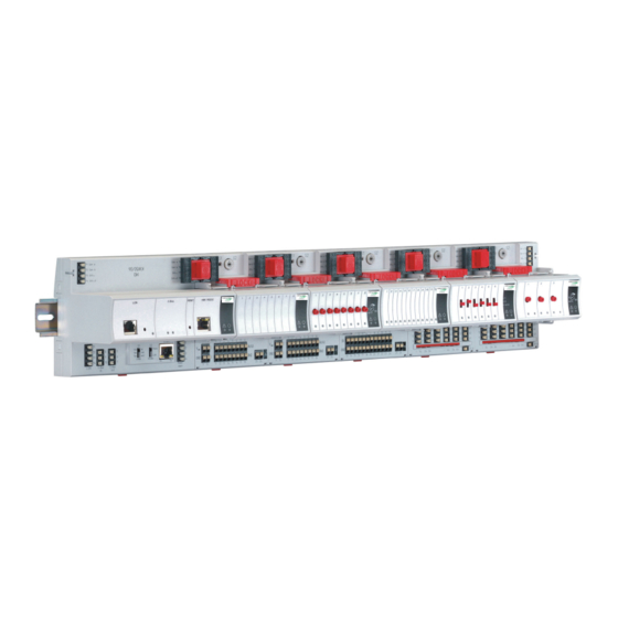
LION Controller
CONTENTS
Safety Information ............................................................... 2
General Safety Information ............................................. 2
Safety Information as per EN60730-1 ............................. 2
System Overview ................................................................ 3
System Architecture ........................................................ 3
I/O Modules ..................................................................... 4
Interfaces and Bus Connections ..................................... 7
Technical Data ................................................................. 7
Planning ............................................................................... 8
Overview .......................................................................... 8
Transformer Selection ..................................................... 8
Fusing Specifications ...................................................... 9
System Protective Earth Grounding ................................ 9
Lightning Protection ......................................................... 9
Panel Bus Topologies ..................................................... 9
Bus Topologies ........................................... 10
C-Bus Topologies .......................................................... 10
Accessories ................................................................... 10
Cable Specifications ...................................................... 11
Dimensions .................................................................... 14
Mounting/Dismounting Modules ..................................... 16
Mounting/Dismounting Controller/Sockets .................... 16
Mounting/Dismounting Electronic Modules ................... 18
Mounting/Dismounting Cross Connectors .................... 21
Mounting/Dismounting Swivel Label Holders ............... 21
Wiring and Setting Up the System .................................. 22
General Safety Considerations ..................................... 22
Wiring Push-in Terminals .............................................. 22
Connecting Power Supply ............................................. 23
Connecting Single Bus Controller Systems .................. 24
Connecting Panel Bus and L
Controller Systems ........................................................ 25
Setting Address of Panel Bus I/O Modules ................... 27
Setting I/O Bus Switch ................................................... 27
Connecting Field Devices ............................................. 28
Commissioning I/O Modules ......................................... 29
Copyright © 2015 Honeywell GmbH ● All Rights Reserved
Bus Mixed
Installation &
Commissioning
Instructions
INSTALLATION AND COMMISSIONING INSTRUCTIONS
Updating Software ......................................................... 29
Connecting to External Systems or Interfaces .............. 30
Connecting via C-Bus .................................................... 31
Connecting HMIs or Laptops ......................................... 31
Connecting Modems ...................................................... 31
Description of the CLLIONLC01 ....................................... 32
Overview ........................................................................ 32
Features ......................................................................... 33
Description of the I/O Modules ........................................ 38
Common Features ......................................................... 38
Troubleshooting ................................................................ 39
Testing Wiring Connections ........................................... 39
Troubleshooting on the CLLIONLC01 Controller .......... 39
Appendix 1: System Protective Earth Grounding .......... 43
LION Systems and SELV .............................................. 43
LION Systems and Standard EN60204-1 ..................... 43
Appendix 2: Remote Communications ........................... 45
Approved Modems ......................................................... 45
Modem or ISDN Terminal Adapter Connection ............. 45
Modem Requirements.................................................... 45
Troubleshooting ............................................................. 45
Appendix 3: Sensor Characteristics ............................... 46
BALCO 500 .................................................................... 46
NTC 20 k ..................................................................... 47
PT 1000 .......................................................................... 48
NI1000TK5000 ............................................................... 50
NTC 10 kΩ ..................................................................... 51
PT 3000 .......................................................................... 52
Trademark Information
Echelon, LON, L
M
ON
trademarks of Echelon Corporation registered in the United
States and other countries.
3.4
LION
SYSTEM
Bus ..................................... 30
, L
T
, L
W
, Neuron, are
ARK
ON
ALK
ON
ORKS
EN1Z-0921GE51 R0315
Advertisement
Table of Contents
Troubleshooting

Related Manuals for Honeywell Centraline LION


Summary of Contents for Honeywell Centraline LION
-
Page 1: Table Of Contents
Setting I/O Bus Switch ........... 27 trademarks of Echelon Corporation registered in the United Connecting Field Devices ..........28 States and other countries. Commissioning I/O Modules ......... 29 Copyright © 2015 Honeywell GmbH ● All Rights Reserved EN1Z-0921GE51 R0315... -
Page 2: Safety Information
Safety Information LION System Safety Information General Safety Information Safety Information as per EN60730-1 When performing any work (installation, mounting, start- Purpose ► up), all instructions given by the manufacturer and in The LION System is an incorporated electronic control particular the safety instructions provided in these system for cabinet mounting. -
Page 3: System Overview
LION System System Overview System Overview System Architecture A LION System consists of the CLLIONLC01 Controller and various I/O modules. The CLLIONLC01 Controller provides interface connections, which allow connection to external systems. Auxiliary parts enable special features. Panel I/O (CLIOPxx) Panel Bus (<40 m) existing XL500 controllers... -
Page 4: I/O Modules
CLIOL822A CLIOL823A CLIOL824A CLIOPR822A CLIOPR824A CLIOPR825A CLIOP830A PANEL BUS MODULES Honeywell Binary Inputs Analog Inputs Analog Outputs 24V Relays AI6 AI7 CO1 CO2 CO3 CO4 CO5 CO6 AI2 AI3 NO1 NO2 NO3 NO4 NO5 NO6 1 2 3 4 5 6 7 8 9 10 11 12 1 2 3 4 5 6 Install. - Page 5 LION System System Overview I/O Module Overview Panel Bus ORKS Description Inputs Outputs Manual controls LEDs module Bus module CLIOP821A CLIOL821A Analog input module – – – CLIOP822A CLIOL822A Analog output module – – 8 status LEDs CLIOPR822A CLIOLR822A Analog output module –...
- Page 6 System Overview LION System Auxiliary Parts Corresponding Module Type Figure I/O modules Information CLIOP/CLIOL… …821 Module allows disconnection of XS812 …822 individual I/O signals. …823 Manual disconnect modules Module allows disconnection of …824 individual I/O signals. XS812RO …825 For 24 V applications only. Two groups of 7 terminals All pluggable LION I/O XS814...
-
Page 7: Interfaces And Bus Connections
LION System System Overview Interfaces and Bus Connections Standards The LION System can be connected to the following devices Protection class IP20 and systems: Product standard EN 60730-1 (EMC) EN 60730-2-9 Panel Bus For communication with up to 16 Panel Bus I/O modules Testing electrical IEC68 components... -
Page 8: Planning
Planning LION System Planning Overview Transformer Selection Engineering with CARE NOTE: In Europe, the system transformer(s) must be safety isolating transformers according to During CARE engineering, the type of I/O modules, terminal IEC61558-2-6. assignment and module configuration are defined In the U.S.A. and Canada, NEC Class-2 depending on the application. -
Page 9: Fusing Specifications
LION System Planning CentraLine 1450 Series (North America) Power Supply of Field Devices 50/60 Hz Depending upon the power consumption of the field devices Insulated accessory outputs used, it is possible to use either a single transformer to power both the CLLIONLC01 and attached field devices, or ... -
Page 10: Lon Works Bus Topologies
Planning LION System Bus Topologies Accessories ORKS The L Bus is a 78-kilobit serial link that uses Besides the auxiliary parts of Table 5 on page 6, the ORKS transformer isolation so that the bus wiring does not have a following accessories are available. -
Page 11: Cable Specifications
LION System Planning Bus Termination Modules XW885 Cable Details ORKS RJ45 plug with clip at front RS232 plug and protective sheathing SHIELD sub-D female Type Description XAL-Term2 connection and ter- ORKS mination module, which can be mounted on DIN rails and in fuse boxes Table 15 L Bus termination modules... - Page 12 Planning LION System NOTE: In the event that the limit on the total wire length Bus Cables ORKS is exceeded, the FTT physical layer repeaters (FTT 10A) can be added to interconnect seg- ments. This increases the overall length by an Cable type Max.
- Page 13 LION System Planning C-Bus Cables NOTE: Observe national regulations for C-Bus cables! For Europe; only shielded cable is permitted. For the U.S., shielded or unshielded cable can be used. Cable type Description Recommended for J-Y-(ST)Y shielded, Europe, inside cabinet 2 x 2 x 0.8 twisted pair A-Y-(ST)Y shielded,...
-
Page 14: Dimensions
Planning LION System Dimensions Controller Module 92.75 Fig. 11 Controller module, outside dimensions (in mm) Pluggable I/O Modules 89.5 94.1 LOCK SCREW-TYPE 30.6 TERMINALS SWIVEL LABEL HOLDER XS814 Aux. Terminal Package (optional) 51.5 Fig. 12 Pluggable I/O modules (shown with manual overrides), including XS814 Aux. Terminal Package, dimensions (in mm) EN1Z-0921GE51 R0315... - Page 15 LION System Planning Mixed I/O Module 92.5 COM a COM a External COM b COM b 24V~ 24V~ 24V~0 24V for relay 1...5 24V~0 Binary Inputs Analog Inputs Analog Outputs 24V Relays B8 B9 B10 B11 B12 AI5 AI6 AI7 AI8 AO6 AO7 AO8 IN1 IN2 IN3 IN4 IN5 IN6 10 11 12 18 19 20...
-
Page 16: Mounting/Dismounting Modules
Mounting/Dismounting Modules LION System Mounting/Dismounting Modules Mounting/Dismounting Controller/Sockets WARNING Mounting Sockets Risk of electric shock or equipment damage! NOTE: When using both Panel Bus and L ORKS Do not touch any live parts in the cabinet. ► I/O modules in a LION System, group both Disconnect the power supply before you start to install ►... - Page 17 LION System Mounting/Dismounting Modules Angle the terminal socket at the upper edge of the DIN Connecting Sockets ► rail until it snaps in. Controller, terminal sockets, and mixed I/O modules on the Swing the terminal socket down and apply gentle force ►...
-
Page 18: Mounting/Dismounting Electronic Modules
Mounting/Dismounting Modules LION System Mounting/Dismounting Electronic Modules Dismounting Sockets Disconnecting Sockets Mounting Electronic Modules Release all bridge connectors before removing the controller module and/or the terminal sockets and/or mixed I/O NOTE: Electronic modules can be removed from the modules from the DIN rail. socket or inserted into the sockets without switching off the power supply, but the resultant behavior of connected field devices must be... -
Page 19: Mounting/Dismounting Manual Disconnect Modules
LION System Mounting/Dismounting Modules Mounting/Dismounting Manual Disconnect Dismounting Electronic Modules Modules NOTE: Electronic modules can be removed from the socket or inserted into the sockets without switching off the power supply, but the resultant XS812 and XS812RO Manual Disconnect Modules are behavior of connected field devices must be mounted on the terminal socket appropriate for the elec- taken into consideration. -
Page 20: Mounting/Dismounting Auxiliary Terminal Packages
Mounting/Dismounting Modules LION System Mounting/Dismounting Auxiliary Terminal Operating the Individual Switches Packages Use a screwdriver to open/close the appropriate ► disconnector switches of the manual disconnect modules. The XS814 Auxiliary Terminal Package can be mounted on any pluggable I/O module. The XS830 and XS831 Auxiliary Terminal Packages are suitable for mixed I/O modules, only. -
Page 21: Mounting/Dismounting Cross Connectors
LION System Mounting/Dismounting Modules Mounting/Dismounting Cross Connectors Mounting/Dismounting Swivel Label Holders NOTE: The cross connector (incl. in the delivery) can be mounted to the XS824-25 or XSU824-25, as NOTE: A swivel label holder is included in the delivery of required. It can be dismounted (see Fig. 28). It is each module. -
Page 22: Wiring And Setting Up The System
Wiring and Setting Up the System LION System Wiring and Setting Up the System General Safety Considerations Wiring Push-in Terminals When connecting the CLLIONLC01 or LION I/O modules, The terminal sockets of the pluggable I/O modules are available in versions (XS821-22, XS823, and XS824-25) both VDE, National Electric Code (NEC) or equivalent, featuring convenient push-in terminals for easy wiring. -
Page 23: Connecting Power Supply
LION System Wiring and Setting Up the System Connecting Power Supply Additional Transformer Connect the additional transformer in a second room or ► The LION System can be powered by one or more external cabinet to terminals 73 and 74 or 77 and 78 of an transformers. -
Page 24: Connecting Single Bus Controller Systems
Wiring and Setting Up the System LION System Connecting Single Bus Controller Systems Panel Bus I/O Modules in Separate Rooms In this scenario, communication and reference voltage This section describes how to connect a controller system (24 V0) must be connected between the rooms. which uses Panel Bus I/O modules only or L ORKS Connect the last module of room 1 to the first module of... -
Page 25: Controller Systems
LION System Wiring and Setting Up the System Connecting Panel Bus and L LonWorks Bus I/O Modules in Separate Rooms ORKS Mixed Controller Systems In this scenario, only communication lines must be connected between the rooms. Connect the last module of room 1 to the first module of Connecting I/O Modules with Each Other ►... - Page 26 Wiring and Setting Up the System LION System Panel Bus I/O modules Panel Bus I/O modules CLLIONLC01 XF... LonWorks Bus I/O modules Fig. 35 Mixed bus system – correct wiring Panel Bus I/O modules LonWorks Bus modules CLLIONLC01 Fig. 36 Mixed bus system –...
-
Page 27: Setting Address Of Panel Bus I/O Modules
LION System Wiring and Setting Up the System Setting Address of Panel Bus I/O Modules Setting I/O Bus Switch During engineering, each Panel Bus I/O module is assigned Set the I/O Bus switch S2 of the CLLIONLC01 depending ► its own unique address. For the sake of clarity for on the modules connected to terminals 71 …... -
Page 28: Connecting Field Devices
Wiring and Setting Up the System LION System Connecting Field Devices Cabling Field Devices Connecting Field Devices with Power Supply Cable Routing Depending on the distance from the controller, field devices Route low-voltage signal and output cables separately from can be supplied by the controller or need a separate mains cables. -
Page 29: Commissioning I/O Modules
LION System Wiring and Setting Up the System Commissioning I/O Modules Example Status before update: The CLLIONLC01 Controller was loaded with controller firmware V3.01.03, which included the Commissioning Panel Bus I/O Modules corresponding Panel Bus I/O module firmware (see Fig. 41). During engineering, the HEX address of the Panel When the controller firmware is updated from V3.01.03 to I/O modules is defined. -
Page 30: Connecting To External Systems Or Interfaces
Connecting to External Systems or Interfaces LION System Connecting to External Systems or Interfaces Termination Example WARNING LONWORKS TERMINATION PLUG-IN JUMPER Risk of electric shock or equipment damage! Do not touch any live parts in the cabinet! ► Disconnect the power supply before making connections ►... -
Page 31: Connecting Via Lon Works
LION System Connecting to External Systems or Interfaces Connecting via C-Bus Connecting HMIs or Laptops Via C-Bus, a LION Controller can be connected to other HMIs (e.g., the CLMMI00N22 or the CLMMI00N31) can be controller systems to form a network. connected via the HMI interface of the CLLIONLC01. -
Page 32: Description Of The Cllionlc01
Description of the CLLIONLC01 LION System Description of the CLLIONLC01 Overview Panel I/O (CLIOPxx) Panel Bus (<40 m) existing XL500 controllers CLLIONLC01 + CLIOxx C-Bus LonWorks Bus MODEM CLMMI00N22 or CLMMI00N31 LonWorks I/O (CLIOLxx) XFCxxx XFCLxxx SERVAL Fig. 44 Connections to the CLLIONLC01 Controller Legend Power supply for I/O modules I/O Bus communication terminals... -
Page 33: Features
LION System Description of the CLLIONLC01 Features CLLIONLC01 Terminals Interface and Terminals ORKS The CLLIONLC01 Controller Module features An RJ45 socket serving as an interface to connect laptops to the L ORKS 8765432 1 L terminals 11, 12, 13, and 14 to connect ORKS Bus I/O modules or other L devices... - Page 34 Description of the CLLIONLC01 LION System C-Bus Tx LED and Rx LED HMI Interface The CLLIONLC01 is equipped with a Tx LED (status: The controller module is equipped with an HMI Interface for yellow/OFF) and an Rx LED (status: yellow/OFF). the connection of HMIs (e.g., the CLMMI00N22 or the CLMMI00N31) or a laptop (with XL-Online/CARE).
- Page 35 LION System Description of the CLLIONLC01 Power LED (2, green) Alarm and Power LEDs Normal operation The CLLIONLC01 is equipped with an alarm LED and a Flashing One or more of the internal voltage power LED. supplies are outside of the permissible ranges.
- Page 36 Description of the CLLIONLC01 LION System Modem Interface I/O Bus Switch S2 The controller module is equipped with a modem interface The CLLIONLC01 features a 2-position I/O Bus switch S2. for the connection of a modem or an ISDN terminal adapter. I/O Bus switch S2 must be set in accordance with the kind of I/O modules connected to communication terminals 71, 72 and 75, 76 of the controller module.
- Page 37 LION System Description of the CLLIONLC01 C-Bus Termination Switch S1 The CLLIONLC01 features a 3-position C-Bus termination switch S1. This switch must be set in accordance with the given C-Bus configuration. 9.6k al l mi d C-Bus Fig. 55 C-Bus termination switch Switch Baud rate setting S1...
-
Page 38: Description Of The I/O Modules
Description of the I/O Modules LION System Description of the I/O Modules Common Features Switches located on the Terminal Socket Feature Function Service LED test, see section "Troubleshooting" button S1 on page 39 (pluggable I/O L service button functionality ORKS modules, for L... -
Page 39: Troubleshooting
LION System Troubleshooting Troubleshooting Testing Wiring Connections Push-in terminals feature small holes (1 mm in diameter) which can be used to measure the signals. Insert a probe (1) as shown on the right. ► Fig. 56 Testing wiring connections Troubleshooting on the CLLIONLC01 Controller The following LEDs of the CLLIONLC01 Controller can be used for troubleshooting purposes: ... - Page 40 Troubleshooting LION System Alarm LED (red) Case Alarm LED Meaning Remedy Normal operation No action necessary Watchdog alarm output is powered Try powering down and then ► – The controller has encountered a powering up the CLLIONLC01. hardware problem If the problem persists, check and – if ►...
- Page 41 LION System Troubleshooting Service LED ORKS Fig. 57 Flashing pattern of the L service LED ORKS The L service LED of the controller module displays the following flashing patterns indicating possible failure modes: ORKS case When can it occur? Meaning Remedy Node is configured and running normally Anytime...
- Page 42 Troubleshooting LION System C-Bus Tx and Rx LEDs case C-Bus LEDs Meaning Remedy If the C-bus is functioning properly, then the Both LEDs are flashing No action necessary CLLIONLC01 Controller is functioning properly If the C-bus is not functioning properly, then Check C-bus termination switch S1 ►...
-
Page 43: Appendix 1: System Protective Earth Grounding
LION System Troubleshooting Appendix 1: System Protective Earth Grounding LION Systems and SELV Earth Grounding of EN60204-1 Applicable Systems In order to avoid distribution of noise or earth ground potential differences over networks or other connections, the If system protective earth grounding is planned, use a ►... - Page 44 Troubleshooting LION System Power Supply and Earthing of LION with Multiple LION and Multiple Controllers, Connected by C- Controllers Connecting a LION System together with other controllers Connecting a C-Bus with controllers earth-grounded as per earth-grounded as per EN60204-1 EN60204-1 NOTE: Use a noise-free earth ground inside the cabinet.
-
Page 45: Appendix 2: Remote Communications
CLLIONLC01 Controller. Modem Requirements A “Frequently Asked Questions and Troubleshooting” document is available via the Honeywell Technical Assistance Center (TAC) or, for Honeywell employees, on the Intranet under: http://web.ge51.honeywell.de/tac Go there, and enter the catchword "modemfaq" in the ►... -
Page 46: Appendix 3: Sensor Characteristics
Appendix 3: Sensor Characteristics LION System Appendix 3: Sensor Characteristics NOTE: The following sensor characteristics do not include failures due to: ● sensor failures; ● wiring resistance or wiring failures; ● Misreadings due to a meter connected to measure resistance or voltage at the input. BALCO 500 Temp. -
Page 47: Ntc 20 K
LION System Appendix 3: Sensor Characteristics NTC 20 k Temp. Resistance Terminal Temp. Resistance Terminal Temp. Resistance Terminal Temp. Resistance Terminal [°C] voltage [V] [°C] voltage [V] [°C] voltage [V] [°C] voltage [V] [k [k [k [k -50.0 1659 8.78 53.8 6.30 60.0... - Page 48 Appendix 3: Sensor Characteristics LION System PT 1000 Temp. Resistance Terminal Temp. Resistance Terminal Temp. Resistance Terminal Temp. Resistance Terminal [°C] [ voltage [V] [°C] [ voltage [V] [°C] [ voltage [V] [°C] [ voltage [V] -50.0 0.312 10.0 1039 0.401 70.0 1271...
- Page 49 LION System Appendix 3: Sensor Characteristics Temp. Resistance Terminal Temp. Resistance Terminal Temp. Resistance Terminal Temp. Resistance Terminal [°C] [ voltage [V] [°C] [ voltage [V] [°C] [ voltage [V] [°C] [ voltage [V] 190.0 1722 0.647 250.0 1941 0.723 310.0 2156 0.797...
-
Page 50: Ni1000Tk5000
Appendix 3: Sensor Characteristics LION System NI1000TK5000 Temp. Resistance Terminal Temp. Resistance Terminal Temp. Resistance Terminal Temp. Resistance Terminal [°C] [Ω] voltage [V] [°C] [Ω] voltage [V] [°C] [Ω] voltage [V] [°C] [Ω] voltage [V] 1081.4 0.416 1316.3 0.502 1580.2 0.597 871.7 0.338... -
Page 51: Ntc 10 Kω
LION System Appendix 3: Sensor Characteristics NTC 10 kΩ Resistance Resistance Resistance Resistance Temp. Terminal Temp. Terminal Temp. Terminal Temp. Terminal [°C] [k voltage [V] [°C] [k voltage [V] [°C] [k voltage [V] [°C] [k voltage [V] 7.904 18.087 3.998 3.099 1.092 0.765... - Page 52 Appendix 3: Sensor Characteristics LION System PT 3000 Temp. Resistance Terminal [°C] [k voltage [V] 2.823 1.018 2.868 1.033 2.913 1.047 2.957 1.061 3.002 1.076 3.046 1.090 3.090 1.104 3.134 1.118 3.178 1.132 3.222 1.146 3.266 1.160 3.310 1.173 3.353 1.187 3.397 1.200...
- Page 53 LION System Appendix 3: Sensor Characteristics EN1Z-0921GE51 R0315...
- Page 54 LION Manufactured for and on behalf of the Environmental and Combustion Controls Division of Honeywell Technologies Sàrl, Rolle, Z.A. La Pièce 16, Switzerland by its Authorized Representative: CentraLine Honeywell GmbH Böblinger Strasse 17 71101 Schönaich, Germany Phone +49 (0) 7031 637 845 +49 (0) 7031 637 740 info@centraline.com...
Need help?
Do you have a question about the Centraline LION and is the answer not in the manual?
Questions and answers