
Related Manuals for Dover PSG ALL-FLO G Series


Summary of Contents for Dover PSG ALL-FLO G Series
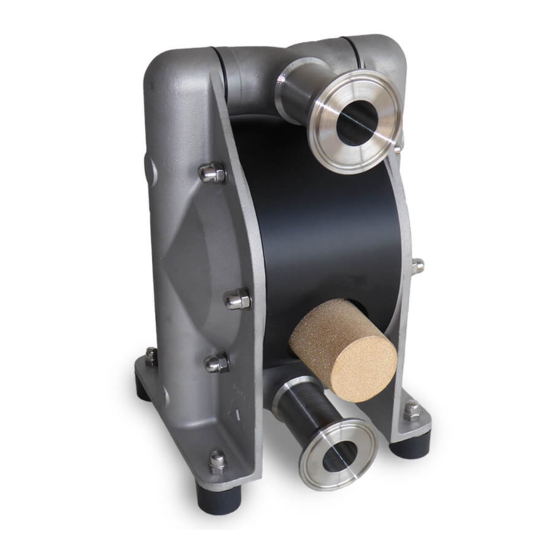
- Page 1 INSTALLATION OPERATION & MAINTENANCE G075 - G200 3/4, 1-1/4, AND 2 INCH FOOD GRADE AIR-OPERATED DOUBLE-DIAPHRAGM PUMPS...
-
Page 2: Table Of Contents
TABLE OF CONTENTS SECTION 1 WARNINGS, DANGERS AND CAUTIONS SECTION 2 MODEL DESIGNATION MATRIX SECTION 3 PRINCIPLES OF OPERATION SECTION 4 DIMENSIONAL DRAWINGS SECTION 5 PERFORMANCE CURVES G075, G125, G200 ................7 SECTION 6 INSTALLATION, INSTALLATION AND OPERATION ............8 TROUBLESHOOTING ..............12 SECTION 7 REPAIR AND ASSEMBLY DISASSEMBLY ................14... -
Page 3: Alf-13400-E
SECTION CAUTIONS — READ FIRST! READ THESE WARNINGS AND SAFETY PRECAUTIONS PRIOR = Hazards or unsafe practices WARNING TO INSTALLATION OR OPERATION. FAILURE TO COMPLY which could result in severe WITH THESE INSTRUCTIONS COULD RESULT IN PERSONAL personal injury, death or INJURY AND OR PROPERTY DAMAGE. -
Page 4: Model Designation Matrix
SECTION MODEL DESIGNATION MATRIX PUMP SIZE DIAPHRAGMS PORTING 075 = 3/4 in. (1 in. Tri-Clamp®) P = Integral PTFE G = Suction Center Rear / Discharge Center Rear 125 = 1-1/4 in. (1-1/2 in. Tri-Clamp®) M = FDA EPDM 200 = 2 in. (2 in. Tri-Clamp®) SPECIAL OPTION (HARDWARE, VALVE/BALL MUFFLER, LUG) -
Page 5: Principles Of Operation
SECTION PRINCIPLES OF OPERATION HOW AN AIR OPERATED DOUBLE DIAPHRAGM PUMP WORKS The air-valve directs pressurized air behind the diaphragm on the right, causing the diaphragm on the right to move outward (to the right). Since both the right diaphragm and the left diaphragm are connected via a diaphragm rod, when the right diaphragm moves to the right, the left diaphragm (through the action of the diaphragm rod) moves to the right also. -
Page 6: Pump Dimensions
SECTION PUMP DIMENSIONS inch G075 1/4" 1" TC G125 12.2 11.2 1/4" 1-1/2" TC G200 12.6 10.6 16.6 15.2 1/2" 2" TC G075 1/4" 1" TC G125 1/4" 1-1/2" TC G200 1/2" 2" TC ALF-13400-E-01 All-Flo... -
Page 7: Performance Curves
SECTION PERFORMANCE CURVES G075 PERFORMANCE CURVE G075 Performance Specifications Max. Flow: 20 gpm (75 lpm) Max. Air Pressure: 100 psi (7 bar) AIR CONSUMPTION (SCFM) Max. Solids: 7/20” (9 mm) Max. Suction Lift Dry (EPDM): 6.6 ft-H O (2 m-H Max. -
Page 8: Installation And Operation
SECTION INSTALLATION, TROUBLESHOOTING For inflammable liquids as well as for applications in in the center block [16]. Use threadseal only sparingly, explosion-proof areas, All-Flo G Series pumps have otherwise the connections could be damaged. been equipped with a center section in conductive The operator is responsible for an adequately stability polyethylene. - Page 9 increase the distance to the dew point of the air. by a closed discharge, the pressure equilibrium of the Doing so, it has to be considered that the driving air diaphragms must be ensured. This can be achieved temperature generally may not exceed 122°F (50°C) by keeping the pump connected to the air supply to avoid expansion and sticking effects on the air side.
-
Page 10: Troubleshooting
SAFETY INSTRUCTIONS • Pools of liquid which appear in the near outer area of the pump have to be inspected on danger potential, if • Installation, operation, and maintenance by qualified necessary safety measures are to be taken. staff only. •... - Page 11 SUBMERGED OPERATION ADDITIONAL TEMPERATURE Consider the following advises when using a All-Flo CONSIDERATIONS pump as a submersible pump: When immersing an The temperature and pressure limitations listed on air- operated diaphragm pump, it must generally page 3 are solely based on mechanical temperature be ensured that the waste air is deducted above the limits of the housing material used.
- Page 12 TROUBLESHOOTING Problem Possible Reason Solutions/Remarks pump does not operate air supply line blocked/closed open air supply muffler blocked clean/replace muffler working chambers blocked remove blockage air control system defective replace air valve system discharge line blocked/closed clean/open line pump operates unsteadily piston rings worn replace piston rings air control system worn...
- Page 13 TROUBLESHOOTING Problem Possible Reason Solutions/Remarks pumps operates, however suction pump operates too fast start more slowly capacity insufficient operation beyond physical limits adjust installation cavitation check, cool down operation beyond pump capacity adjust installation resp. install bigger pump air cushion within suction/discharge bleed the line line dry suction against discharge pressure...
-
Page 14: Disassembly
SECTION REPAIR AND ASSEMBLY DISASSEMBLY When dismantling a pump the mentioned procedures and safety notes on the pages 3 and 10 have to be considered generally. The general design of the G Series pumps is simple. A plastic tool designed for the mounting of the air-valve [22] is delivered along with every pump. -
Page 15: Assembly
SECTION REPAIR AND ASSEMBLY For pumps with draining systems only: Take out the locking handle of the black flushing system [30]; draw off the pressure plate and the outer O-Ring and take out the ball lifter from inside the side housings [1]; withdraw inner O-ring. Remove the center block [16] by Screw one diaphragm [14] counter Pull the other diaphragm [14]... - Page 16 REPAIR AND ASSEMBLY ASSEMBLY The re-assembly of the components is principally carried out vice-versa to the dismantling. Here are some additional references. For the installation of the air control system, first screw in one end cap flushly into the center block [16]. Insert one of the six O-rings, air-valve housing [24] into the end cap from the inside.
- Page 17 SECTION EXPLODED VIEW & PARTS LIST ALF-13400-E-01 All-Flo...
-
Page 18: Parts List
PARTS LIST PUMP SIZE G075 G125 G200 ITEM DESCRIPTION MATERIAL PART NUMBER PUMP HOUSING, LIQUID SECTION 3 316 STAINLESS STEEL 5 20 210 26 5 32 210 26 5 50 210 26 TRI-CLAMP SUCTION/DISCHARGE PORT, LIQUID SECTION 3 316 STAINLESS STEEL 5 20 211 26 5 32 211 26 5 50 211 26... - Page 19 SECTION ELASTOMERS WETTED ELASTOMERS EPDM PTFE (POLYTETRAFLUOROETHYLENE) is a general purpose elastomer with good resistance is a thermoplastic polymer that is inert to most to many acids and bases. chemicals. All wetted elastomers used in G Series pumps are FDA-approved. A material-certificate stating FDA-conformity can be ordered.
-
Page 20: Warranty And Registration
SECTION WARRANTY AND REGISTRATION WARRANTY. All All-Flo products shall be covered by the standard All-Flo Limited Warranty in effect at the time of shipment. This warranty (which may be modified by All-Flo at any time) provides: MATERIALS SOLD ARE WARRANTED TO THE ORIGINAL USER AGAINST DEFECTS IN WORKMANSHIP OR MATERIALS UNDER NORMAL USE (RENTAL USE EXCLUDED) FOR FIVE YEARS AFTER PURCHASE DATE. - Page 21 NOTES ALF-13400-E-01 All-Flo...
- Page 22 NOTES ALF-13400-E-01 All-Flo...
- Page 23 22069 Van Buren Street Grand Terrace, CA 92313-5651 USA P: +1 (440) 354-1700 F: +1 (440) 354-9466 all-flo.com All-Flo is committed to the pursuit of designing and manufacturing the highest quality product available to industry. Since the beginning in 1986, All-Flo engineers have used their extensive knowledge of today’s engineered materials, advanced air system logic and manufacturing techniques to develop the superior group of lube-free, air-operated diaphragm pumps found in this catalog.
Need help?
Do you have a question about the PSG ALL-FLO G Series and is the answer not in the manual?
Questions and answers