Table of Contents
Advertisement
Quick Links
P15 - P25 - P40 - P60 - P100
P Series pumps are covered 24 months by warranty within the limits mentioned in our General Sales Conditions. In case of a use
other than that mentioned in the Instructions manual, and without preliminary agreement of MOUVEX, warranty will be canceled.
Z.I. La Plaine des Isles - F 89000 AUXERRE - FRANCE
Tel. : +33 (0)3.86.49.86.30 - Fax : +33 (0)3.86.49.87.17
contact@mouvex.com - www.mouvex.com
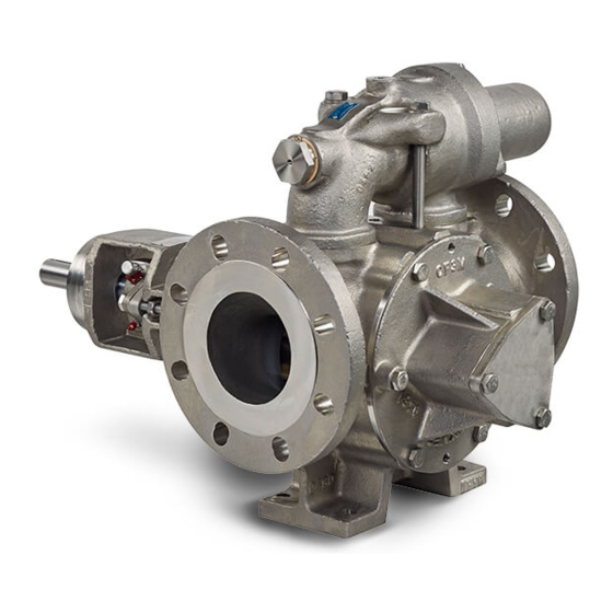
P BA series
WARRANTY :
INSTRUCTIONS 1008-C00 e
Cross-section 1008
Effective
July 2018
Replaces
September 2016
Original instructions
INSTALLATION
MAINTENANCE
Your distributor :
USE
Advertisement
Table of Contents

Related Manuals for Dover PSG Mouvex P BA Series


Summary of Contents for Dover PSG Mouvex P BA Series
- Page 1 INSTRUCTIONS 1008-C00 e Cross-section 1008 Effective July 2018 Replaces September 2016 Original instructions P BA series P15 - P25 - P40 - P60 - P100 INSTALLATION MAINTENANCE WARRANTY : P Series pumps are covered 24 months by warranty within the limits mentioned in our General Sales Conditions. In case of a use other than that mentioned in the Instructions manual, and without preliminary agreement of MOUVEX, warranty will be canceled.
-
Page 2: Table Of Contents
VANES PUMPS SAFETY, STORAGE, INSTALLATION AND MAINTENANCE INSTRUCTIONS MODELS : P BA SERIES P15 - P25 - P40 - P60 - P100 Page TABLE OF CONTENTS 1. DIMENSIONS ........3 2. -
Page 3: P15
1. DIMENSIONS P15 - P25 BA Stirrup 4 holes Ø 14 Space required for removing front cover Pump plate ATEX plate Weight : 38 kg Suction Discharge 4 holes Ø 18 at 90° on Ø 145 Space required for removing cap P15 - P25 BA Bypass adjustment Space required for removing front cover... - Page 4 1. DIMENSIONS (continued) Space required for removing cap P15 - P25 BA Bypass adjustment Space required for removing front cover Double bypass Pump plate ATEX plate Inserting M6 sensor * 4 holes Ø 14 Thread size : 8 mm max. Weight : 46 kg Discharge...
- Page 5 1. DIMENSIONS (continued) Space required for removing cap P15 - P25 BA Bypass adjustment Space required for removing front cover Jacket Reheating jacket port Double bypass Pump plate ATEX plate Inserting M6 sensor * thread size : 8 mm max. 4 holes Ø...
- Page 6 1. DIMENSIONS (continued) Space required for removing cap P40 BA Bypass adjustment Space required for removing front cover Single bypass Pump plate ATEX plate Inserting M6 sensor thread size : 8 mm max. 4 holes Ø 14 Weight : 64 kg 8 holes Ø...
- Page 7 1. DIMENSIONS (continued) Reheating jacket port P40 BA Draining the jacket Pump plate Jacket Space required for removing front cover Stirrup 4 holes Ø 14 Weight : 66 kg 4 M12 at 90° on Ø 65 for CB ISO PN16 DN15 4 M12 at 90°...
- Page 8 1. DIMENSIONS (continued) P40 BA Space required for removing cap Bypass adjustment Jacket Space required for removing front cover Pump plate Double bypass Reheating jacket port Draining the jacket Weight : 74 kg 4 holes Ø 14 4 M12 at 90° on Ø 65 for CB ISO PN16 DN15 8 holes Ø...
- Page 9 1. DIMENSIONS (continued) Space required for removing cap P60 BA Bypass adjustment Space required for removing front cover Single bypass Pump plate ATEX plate Inserting M6 sensor ; Thread size : 8 mm max. 4 holes Ø 14 Weight : 75 kg 8 holes Ø...
- Page 10 1. DIMENSIONS (continued) P60 BA Reheating jacket port Draining the jacket Jacket Space required for removing front cover Pump plate Stirrup 4 holes Ø 14 Weight : 77 kg 4 M12 at 90° on Ø 65 for CB ISO PN16 DN15 4 M12 at 90°...
- Page 11 1. DIMENSIONS (continued) P60 BA Space required for removing cap Bypass adjustment Jacket Space required for removing front cover Double bypass Pump plate Reheating jacket port Draining the jacket 4 holes Ø 14 Weight : 83 kg 4 M12 at 90° on Ø...
- Page 12 1. DIMENSIONS (continued) AJ Space required for removing cap P100 BA Bypass adjustment Space required for removing front cover Single bypass Pump plate PA ATEX plate Inserting M6 sensor Thread size : 8 mm max. 4 holes Ø 18 Weight : 175 kg 8 holes Ø...
- Page 13 1. DIMENSIONS (continued) Reheating jacket port P100 BA Draining the jacket Space required for removing front cover Jacket Pump plate Stirrup 4 holes Ø 18 Weight : 126 kg 4 M12 at 90° on Ø 65 for CB ISO PN16 DN15 8 holes Ø...
- Page 14 1. DIMENSIONS (continued) AJ Space required for removing cap P100 BA Bypass adjustment Space required for removing front cover Jacket Reheating jacket port Double bypass Pump plate Draining the jacket 4 holes Ø 18 Weight : 149 kg 8 holes Ø 18 at 45°...
-
Page 15: Installation
2. INSTALLATION 2.1 Choice of pump 2.4 Piping assembly To obtain the service expected from a MOUVEX P series In order to achieve the best usage conditions, it is impor- pump, regarding both performance and longevity, it is tant to take the following recommendations into account vital that the type of pump, its speed and the materials when it comes to fitting pipes : used for its construction are determined as a function of... -
Page 16: Direction Of Rotation
2. INSTALLATION (continued) 2.5 Direction of rotation 2.6 Protecting the system against overpres- sure • In its standard configuration, the MOUVEX P series pump is supplied as non-reversible and with counter- WARNING clockwise rotation. NOTE : THE VIEWS CONTAINED IN THIS INSTRUCTION MANUAL SHOW PARTS IN THE STANDARD DIRECTION OF ROTATION. -
Page 17: Heating Jacket Variant
2. INSTALLATION (continued) 2.8 Heating jacket variant WARNING 2.8.1 Technical characteristics BEFORE DRAINING THE HEATING JAC- To avoid any liquid solidification in the pump, two heating KET, IT IS ESSENTIAL TO MAKE SURE jackets are located on each side of the body. THAT THE PUMP HEATING CIRCUIT AND HEATING JACKET ARE NO LONGER Heating jackets permits the circulation of steam or liquid... -
Page 18: Installation Of Units
2. INSTALLATION (continued) 2.10 Installation of units 2.11 Alignment of motor/pump and reduction gearbox/pump shafts WARNING WARNING BE CAREFUL WITH THE WEIGHT OF THE IF OPERATED WITHOUT THE SHAFT PARTS WHEN THEY ARE BEING GUARD, THERE IS CONSIDERABLE RISK REMOVED. OF SEVERE PERSONAL INJURY, SIGNIFI- CANT PROPERTY DAMAGE OR EVEN The weight ot the parts... -
Page 19: Electric Motors
2. INSTALLATION (continued) 2.12 Electric motors Start the pump empty to check that the connections are good and that the direction of rotation corresponds to the system intake and discharge directions. If it is necessary WARNING to reverse the direction of rotation, follow the instructions below : Three-phase motor : switch any 2 current input wires. -
Page 20: Use
3. USE 3.1 Pumping hot liquids 3.3 Noise level The sound level of a pump is greatly influenced by its CAUTION conditions of use. Cavitation and pumping products with high gas contents generally increases the sound level. Under the following pumping conditions : THE SURFACES CAN BE AT A TEMPERA- •... -
Page 21: Shutting Down The Pump
3. USE (continued) 3.6 Shutting down the pump The best storage conditions are inside a building that meets the conditions set out above. When shutting down the pump, we recommend waiting If inside storage is not possible, the materials should be for it to stop completely before closing the valves, espe- covered to prevent direct exposure to sun and bad wea- cially the inlet valve. -
Page 22: Opening And Closing The Non-Drive Side Base
5. OPENING AND CLOSING THE NON-DRIVE SIDE BASE WARNING WARNING DISCONNECTING THE FLUID OR PRESSURE CONTAINMENT COMPO- DISCONNECT THE ELECTRICITY NENTS DURING PUMP OPERATION SUPPLY BEFORE ANY MAINTENAN- CAN CAUSE SERIOUS PERSONAL CE OPERATION. INJURY, DEATH OR MAJOR PROPERTY DAMAGE. Hazardous pressure Dangerous voltage. -
Page 23: Opening The Non-Drive Side Base
5. OPENING AND CLOSING THE NON-DRIVE SIDE BASE (continued) 5.1 Opening the non-drive side base • Replace the vane (with a new one if necessary), making sure it is fitted in the right direction (see details • Loosen the 6 screws 410. below) and making sure it slides properly in its slot. -
Page 24: Closing The Non-Drive Side Base
5. OPENING AND CLOSING THE NON-DRIVE SIDE BASE (continued) 5.4 Closing the non-drive side base • Check the seal 403, and replace if necessary. • Place the front cover 401b on the shaft 501 and tighten it as much as possible by hand. •... -
Page 25: Opening And Closing The Drive Side Base
6. OPENING AND CLOSING THE DRIVE SIDE BASE WARNING WARNING DISCONNECTING THE FLUID OR PRESSURE CONTAINMENT COMPO- DISCONNECT THE ELECTRICITY NENTS DURING PUMP OPERATION SUPPLY BEFORE ANY MAINTENAN- CAN CAUSE SERIOUS PERSONAL CE OPERATION. INJURY, DEATH OR MAJOR PROPERTY DAMAGE. Hazardous pressure Dangerous voltage. -
Page 26: Opening The Drive Side Base
6. OPENING AND CLOSING THE DRIVE SIDE BASE (continued) 6.1 Opening the drive side base 6.2 Dismantling the vanes and pushrods • Loosen the 6 screws 410. • Place the front cover 401a and rotor 301 assembly on a bench. •... -
Page 27: Changing The Bushing
6. OPENING AND CLOSING THE DRIVE SIDE BASE (continued) 6.3 Changing the bushing 6.4 Reassembly the vanes and pushrods • Loosen the 3 screws 726. 6.4.1 Shaft with 2 key grooves • Remove the front cover 401a from the strainer 725 by •... - Page 28 6. OPENING AND CLOSING THE DRIVE SIDE BASE (continued) 6.4.2 Shaft with 4 key grooves Pump WITHOUT pushrods Pump WITH pushrods • Put the keys 536 n the grooves WITHOUT circular • Put the keys 536 in the grooves a circular mark. marks.
-
Page 29: Closing The Drive Side Base
6. OPENING AND CLOSING THE DRIVE SIDE BASE (continued) 6.5 Closing the drive side base • Insert the pushrods 318 in the holes on the rotor 301 (in this case where the rotor has 12 vanes, insert the • Refit the front cover 401a on the pump body 101. pushrods using orthogonal tightening). -
Page 30: Changing The Ball Bearing
7. CHANGING THE BALL BEARING WARNING WARNING DISCONNECTING THE FLUID OR PRESSURE CONTAINMENT COMPO- DISCONNECT THE ELECTRICITY NENTS DURING PUMP OPERATION SUPPLY BEFORE ANY MAINTENAN- CAN CAUSE SERIOUS PERSONAL CE OPERATION. INJURY, DEATH OR MAJOR PROPERTY DAMAGE. Hazardous pressure Dangerous voltage. can cause Can cause personal injury... - Page 31 7. CHANGING THE BALL BEARING (continued) Before any disassembly, make sure that the pump has been Reassembly : drained, and take all the necessary precautions to prevent it • Check that the washer 731 is pressed against the shoulder from starting up. The pump must not start up, even acciden- of the shaft 501.
-
Page 32: Bypass
8. BYPASS Version with plug Installing for High Temperature WARNING WARNING DISCONNECTING THE FLUID OR PRESSURE CONTAINMENT COMPO- DISCONNECT THE ELECTRICITY NENTS DURING PUMP OPERATION SUPPLY BEFORE ANY MAINTENAN- CAN CAUSE SERIOUS PERSONAL CE OPERATION. INJURY, DEATH OR MAJOR PROPERTY DAMAGE. -
Page 33: Bypass Operation
8. BYPASS (continued) Version with plug Installing for High Temperature 8.1 Bypass operation 8.3 Bypass inversion The compensated bypass operates like a valve, by auto- • Loosen the 2 screws 859. matically limiting the discharge pressure at the value for •... -
Page 34: Obtaining The Flow
8. BYPASS (continued) 8.5 Obtaining the flow 8.7 Replacing the spring Before any disassembly, make sure that the pump has WARNING been drained and take all the necessary precautions to prevent it from starting up. The pump must not start up, even accidentally. -
Page 35: Shaft Seal
9. SHAFT SEAL 9.1 Packing WARNING WARNING DISCONNECTING THE FLUID OR PRESSURE CONTAINMENT COMPO- DISCONNECT THE ELECTRICITY NENTS DURING PUMP OPERATION SUPPLY BEFORE ANY MAINTENAN- CAN CAUSE SERIOUS PERSONAL CE OPERATION. INJURY, DEATH OR MAJOR PROPERTY DAMAGE. Hazardous pressure Dangerous voltage. can cause Can cause personal injury... - Page 36 9. SHAFT SEAL (continued) View F Glued with Loctite ® 243* * Loctite ® is a registered brand. 9.1.1 Operation of packing Reassembly : The rings 629 have a static seal at the strainer 725 side and a hydrodynamic seal at the shaft side 501 side. •...
-
Page 37: Mouvex Mechanical Shaft Seal
9. SHAFT SEAL (continued) 9.2 MOUVEX mechanical shaft seal WARNING WARNING DISCONNECTING THE FLUID OR PRESSURE CONTAINMENT COMPO- DISCONNECT THE ELECTRICITY NENTS DURING PUMP OPERATION SUPPLY BEFORE ANY MAINTENAN- CAN CAUSE SERIOUS PERSONAL CE OPERATION. INJURY, DEATH OR MAJOR PROPERTY DAMAGE. - Page 38 9. SHAFT SEAL (continued) View F Glued with Loctite ® 243* * Loctite ® is a registered brand. 9.2.1 Operation of a MOUVEX mechanical shaft tructions. seal Dismantling : The shaft 501 drives the rotating parts 697 (consisting of • Remove the shaft key 508. the reservoir 612, the seal 613, the spring support 614, •...
- Page 39 9. SHAFT SEAL (continued) View F Glued with Loctite ® 243* Reassembly : • Push it on with a sleeve until it comes to bear against the washer 731. Under no circumstances should you • Check that the surfaces in contact with the counterpart push the bearing onto the shaft without holding the 604 and rotating part 697 are in good condition.
-
Page 40: Single Mechanical Shaft Seal
9. SHAFT SEAL (continued) 9.3 Single mechanical shaft seal MOUNTING SHAFT SEALS STANDARDIZED IN ACCORDANCE WITH NF EN 12756 Shaft seal Pump Shaf Ø Mounting dimension Compression variant (L1K -L) dimension PGSN 42,5 (42.5-L)± 0.3 PGSN 42,5 (42.5-L)± 0.3 Refer to P40* PGSN 42,5... - Page 41 9. SHAFT SEAL (continued) 9.3 Single mechanical shaft seal STANDARD : P15 - P25 - P40 - P60 - P100 - JACKET : P15 - P25 View F Glued with Loctite ® 243* JACKET : P40 - P60 - P100 Demounting port details Slope of stan-...
- Page 42 9. SHAFT SEAL (continued) 9.3.1 Operation of a single mechanical shaft seal 9.3.2 Replacing a single mechanical shaft seal The shaft 501 drives the rotating part 697 by means of Before undertaking disassembly, make sure that the pump set screws 617. The counterpart 604 is integrated with has been drained, and take the necessary precautions the shaft seal holder 601 by the seal 605 and the pin 627.
- Page 43 9. SHAFT SEAL (continued) Reassembly : Steps 1 to 9 : Step 12 : • Check that the surfaces in contact with the counter- • Screw the 3 screws 726. parts 604 and rotating part 697 are in good condition. •...
-
Page 44: Remounting A Single Mechanical Shaft Seal With Grease Container
9. SHAFT SEAL (continued) 9.4 Remounting a single mechanical shaft seal with grease container • Fit the lubricator 644 and breather 643. • When fitting a shaft seal with grease reservoir, follow • Unscrew the 2 screws 729 and push the cover 645 out- REPLACING A SINGLE MECHANI- steps 1 to 9 in §... -
Page 45: Double Mechanical Shaft Seal
9. SHAFT SEAL (continued) 9.5 Double mechanical shaft seal MOUNTING SHAFT SEALS STANDARDIZED IN ACCORDANCE WITH NF EN 12756 Seal Pump Shaf Ø Mounting dimension Compression variant (L1K - L) dimension PGDN 42,5 (42.5-L)± 0.3 124,5 A =B PGDN 42,5 (42.5-L)±... - Page 46 9. SHAFT SEAL (continued) 9.5 Double mechanical shaft seal STANDARD : P15 - P25 - P40 - P60 - P100 - JACKET : P15 - P25 G1/4” cleaning port View F Glued with Loctite ® 243* JACKET : P40 - P60 - P100 Demounting port details Slope of standard thread lock...
- Page 47 9. SHAFT SEAL (continued) 9.5.1 Operation of a double mechanical shaft seal 9.5.2 Replacing a double mechanical shaft seal The shaft 501 drives the rotating parts 697 by means of Before undertaking disassembly, make sure that the pump set screws 617. The fixed counterparts 604 are integral, has been drained, and take the necessary precautions one with the shaft seal holder 601 by means of the seal to prevent it from starting up.
- Page 48 9. SHAFT SEAL (continued) Remounting : • Tighten the 2 screws 729 and their nuts 730. • Check the condition of the contact surfaces of the • Slide the strainer 725 onto the shaft 501 until it counterparts 604 and rotating parts 697. contacts the front cover 401a.
-
Page 49: Maintenance
10. MAINTENANCE 10.1 Lubrication of the bearing 10.3 Checking the condition of friction bushings Except for special cases, the MOUVEX P BA series We advise checking the condition of the friction bushings pump does not require lubrication especially for the shaft at the same intervals as the vanes and pushrods. -
Page 50: Troubleshooting
11. TROUBLESHOOTING ZERO OR INSUFFICIENT FLOW RATE PRELIMINARY CHECKS Make sure that the plastic plugs have been taken away from the ports of the pump and that the pump is run- ning (defective drive, damaged motor, etc., faulty transmission : broken coupling, worn or poorly coupled clutch, etc.). - Page 51 11. TROUBLESHOOTING (continued) MEASURING THE VACUUM PRESSURE (as close as possible to the pump inlet, inlet side). If the vacuum is high, e.g. higher than or equal to 6 to 7 meters WC (about 45 or 50 cm of mercury), this can result in pump noise because : The suction head is too high, or : a.
- Page 52 11. TROUBLESHOOTING (continued) ABNORMAL NOISES These noises can be hydraulic or mechanical. They can be distinguished by the fact that only the former disappear (or at least lessen) when air is allowed into the inlet pipe. HYDRAULIC NOISE These noises can come from insufficient product being supplied to the pump, or : - the rotation speed is too high for the installation conditions (increase of viscosity due to a change of product or a reduction of temperature, etc.).
-
Page 53: Certificate Of Conformity
12. CERTIFICATE OF CONFORMITY NT 1008-C00 07 18 P BA series e 53/53...
Need help?
Do you have a question about the PSG Mouvex P BA Series and is the answer not in the manual?
Questions and answers