
Related Manuals for Dover WILDEN PSG T20


Summary of Contents for Dover WILDEN PSG T20
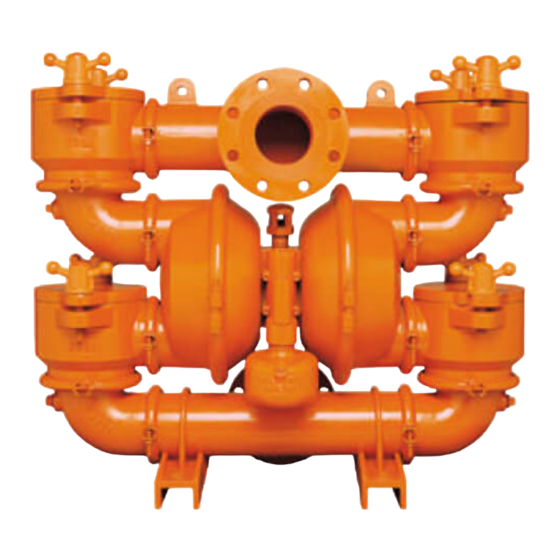
- Page 1 ENGINEERING OPERATION & MAINTENANCE T20 Clamped Metal Pump Where Innovation Flows WIL-10280-E-04...
-
Page 2: Table Of Contents
Contents Section 1: Precautions - Read First! Section 2: Wilden Pump Designation System Section 3: How It Works Section 4: Dimensional Drawings Section 5: Performance T20 M eta l F ood Gr ade / Pol yure tha ne - F itt ed T20 M eta l F K M / PT F E- F itt ed ®... - Page 3 PSG, a Dover Company, except as described by the terms of those agreements. This is a non-contractual document. 01-2019.
-
Page 4: Section 1: Precautions - Read First
Section 1 Precautions - Read First! NOTE: Before starting disassembly, mark a line from TEMPERATURE LIMITS: each liquid chamber to its corresponding air chamber, as well as a line from the liquid chamber to its Neoprene 0°F to 200°F –17.8°C to 93.3°C corresponding discharge elbow and ball pot. - Page 5 Section 2 W I L D E N P U M P D E S I G N A T I O N S Y S T E M T20 METAL LEGEND T20 / X X X X X / XXX / XX / X XX / XXXX O-RINGS MODEL...
- Page 6 HOW IT WORKS — PUMP Section 3 The Wilden diaphragm pump is an air-operated, positive displacement, self-priming pump. These drawings show the flow pattern through the pump upon its initial stroke. It is assumed the pump has no fluid in it prior to its initial stroke. FIGURE 1 The air valve directs pressurized FIGURE When...
- Page 7 Section 4 DIMENSIONAL DRAWING T20 Metal DIMENSIONS ITEM METRIC (mm) STANDARD (inch) 37.4 26.8 32.5 13.0 17.3 16.7 13.1 11.0 17.9 14.8 15 DIA. .6 DIA. 18 DIA. .7 DIA. Rev. B ® Wilden WIL-10280-E-04...
-
Page 8: Section 5: Performance
Section 5 PERFORMANCE T20 METAL Rubber-Fitted Height ......826 mm (32.5") Width ......940 mm (37.0") Depth ......330 mm (13.0") Est. Ship Weight .. Cast Iron 231 kg (500 lbs) Air Inlet........19 mm (3/4") Inlet ........102 mm (4") Outlet ........ -
Page 9: T20 M Eta L W Il- F Le X™ / Pol Y Ureth Ane - F It Te D
PERFORMANCE T20 METAL Wil-Flex™ Polyurethane-Fitted Height ......826 mm (32.5") Width ......940 mm (37.0") Depth ......330 mm (13.0") Est. Ship Weight .. Cast Iron 231 kg (500 lbs) Air Inlet........19 mm (3/4") Inlet ........102 mm (4") Outlet ........ -
Page 10: Section 6: Suggested Installation, Operation
Section 6 Suggested Installation, Operation, Maintenance and Troubleshooting The Model T20 has a 102 mm (4") inlet and 102 mm (4") outlet and is designed and pump damage will not occur. When operation is controlled by a for flows to 1041 lpm (275 gpm). The T20 pump is manufactured with wetted solenoid valve in the air line, a three-way valve should be used. - Page 11 Suggested Installation, Operation, Maintenance and Troubleshooting NOTE: In the event of a power failure, the shutoff valve should be closed, if the restarting of the pump is not desirable once power is regained. Maintenance and Inspections Air-Operated Pumps: To stop the pump from operating in an emergency situation, simply close the “shut-off”...
- Page 12 Suggested Installation, Operation, Maintenance and Troubleshooting Troubleshooting Pump will not run or runs slowly. 3. Check to make sure all suction connections are air tight, Check air inlet screen and air filter for debris. especially clamp bands around intake balls. Check for sticking air valve, flush air valve in solvent.
-
Page 13: Section 7: Disassembly / Reassembly
Section 7 Disassembly / Reassembly Pump Disassembly CAUTION: Before any maintenance or repair is attempted, the compressed air line to the pump should be disconnected and all air pressure allowed to bleed from pump. Disconnect all intake, discharge and air lines. The T20 has a 102 mm (4") inlet and 102 mm (4") outlet and is designed for flows up to 300 gpm. - Page 14 Disassembly / Reassembly Step 1 Figure 1A Figure 1B Start disassembly by removing the wing nuts from the ball pots. This allows the ball pot cover to be removed, exposing the discharge or inlet ball valves and ball pot lid o-rings for inspection. (See Figures 1A, 1B.) Step 2 Figure 2A Figure 2B...
- Page 15 Disassembly / Reassembly Disassembly & Reassembly of Inlet Housing Disassembly Loosen clamp band around inlet elbow. (See Figure 1A.) Remove the clamp band while supporting the elbow. This step will allow for inspection of the manifold gasket between the elbows and inlet-tee. (See Figure 1B.) Repeat this step for removal of opposite elbow.
-
Page 16: Cen Ter S Ec Tio N Hou Si Ng D I Sas Sem Bl Y
Disassembly / Reassembly Disassembly & Reassembly of Center Section Housing Disassembly Step 1 Figure 1A Loosen clamp band around discharge elbow. Remove the clamp band while supporting the elbow. This step will allow for inspection of the manifold gasket between elbows and water chamber. (See Figure 1A.) Repeat this step for removal of opposite elbow. Step 2 Figure 2A Figure 2B... - Page 17 Disassembly / Reassembly Disassembly & Reassembly of Center Section Housing Step 4 Figure 4A Place the center section as shown in Figure 4A. Place a wrench over the nut at the center of each outer piston, and loosen the outer piston plate.
- Page 18 Disassembly / Reassembly Reassembly of Center Section Housing Step 1 Prior to reassembly, remove Glyd™ rings from center block bushing and flush the center block, removing grit and contaminants. Install new Glyd™ rings in center block. Reassemble air valve, center block and air chambers per the torque specifications*. Step 2 Figure 2A Step 3...
- Page 19 Disassembly / Reassembly Step 4 Figure 4A Step 5 Figure 5B Flip the assembly over and stand the unit upright using a block of Return the pump to an upright position. (See Figure 4A.) wood to support the assembly. (See Figure 5A.) Replace the Replace gaskets on both sealing surfaces of the water chamber.
- Page 20 Disassembly / Reassembly Disassembly & Reassembly of Discharge Housing DISASSEMBLY Step 1 Figure 1A Figure 1B Loosen clamp bands between ball pots and discharge tee. Remove the bands while supporting the tee-section. This will allow for inspection of the seals between the ball pots and discharge tee-section (see Figure 1A) as well as inspection of the ball seat found on the bottom side of the ball pot.
- Page 21 Disassembly / Reassembly Reassembly of Pump Body Step 1 With assistance, place the center section housing onto the inlet manifold. Replace clamp bands around the inlet elbows and ball pots and tighten per the torque specification*. Step 2 With assistance, place the discharge assembly onto the discharge elbows. Replace the clamp bands around the discharge elbows and ball pots and tighten per the torque specification*.
-
Page 22: Ai R Va Lve D Is As Sem Bl Y
Disassembly / Reassembly Air Valve / Center Section Disassembly CENTER BLOCK AIR VALVE BODY The air valve assembly consists of both the air valve body and piston and the center block. The unique design of the air valve relies only on differential pressure to effect the diaphragm shift. - Page 23 Disassembly / Reassembly MAXIMUM TORQUE SPECIFICATIONS Item # Description of Part Maximum Torque Air Valve 9.0 N•m (80 in-lbs) Outer Piston 135.6 N•m (78 ft-lbs) 2C Ring & Piston 24.4 N•m (18 ft-lbs) Center Block Assembly 31.2 N•m (23 ft-lbs) Large Clamp Bands 61.0 N•m (45 ft-lbs) Small &...
-
Page 24: Section 8: Exploded View And Parts List
Section 9 EXPLODED VIEW AND PARTS LISTING T20 ORIGINAL METAL EXPLODED VIEW ® Wilden WIL-10280-E-04... - Page 25 Exploded View and Parts List T20/WWWAD Item Description Qty. Air Valve Assembly with Oil Bottle 15-2080-07-225 Air Valve Screen 08-2500-07 Air Valve End Cap with Guide 15-2300-23 Air Valve End Cap without Guide 15-2330-23 Air Valve Snap Ring 15-2650-03 Air Valve Cap O-Ring 15-2390-52 Oil Bottle 15-2850-01...
-
Page 26: Section 9: Elastomer Options
Section 9 Elastomer Options T20 Metal Pumps Material Diaphragm (2) P/N Ultra-Flex Diaphragm (2) P/N Valve Ball (4) P/N Valve Seat (4) P/N Plate O-Ring (4) P/N Manifold Gasket (8) P/N ® Polyurethane 15-1010-50 20-1080-50 20-1120-50 Neoprene 15-1020-51 Buna-N 15-1010-52 15-1020-52 15-1010-53 15-1020-53... - Page 27 Notes WIL-10280-E-04 ® Wilden...
- Page 28 22069 Van Buren Street Grand Terrace, CA 92313-5651 USA 1 (909) 422-1730 • F: 1 (909) 783-3440 psgdover.com Where Innovation Flows ® reserves right to modify information and illustrations contained this document without prior notice. This is non-contractual document. 05- 2018 WIL-10280-E-04 ®...
Need help?
Do you have a question about the WILDEN PSG T20 and is the answer not in the manual?
Questions and answers