Advertisement
Quick Links
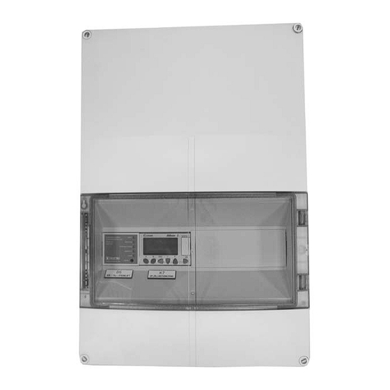
Installation Instructions, Control box for Smoke
Function with Damper Exercising TBLZ-2-48-2
GOLD/COMPACT
1. General
The control box for the smoke function with damper exer-
cising mode consists of a control unit for smoke manage-
ment, a logic unit and a transformer for exercising damp-
ers, mounted in a box with a transparent cover. Necessary
wiring terminals are provided for connection to external
components.
The control box has knockout holes for cable entry
through grommets.
2. Range of Application
The control box is used together with the TBLZ-2-49-a
smoke detectors. On receiving a fault indication, the con-
trol unit is designed to control the dampers, stop the air
handling unit and initiate an alarm.
A preprogrammed logic unit stops the air handling unit
and exercises the dampers at regular time intervals. If the
damper exercising procedure is not satisfactory, an alarm is
initiated. The connected damper actuators must be de-
signed for 24V AC power.
3. Function – Control Unit, Smoke
The control unit is designed to comply with the provisions
made upon reliable fire protection together with our smoke
detectors. The unit is equipped with relay contacts for con-
trolling the dampers and fans. In addition to smoke alarms,
the control unit is equipped with service alarm and fault
alarm relays.
In the event of a smoke alarm, a red LED is lit and the alarm
relays are simultaneously de-energised.
In the event of a service alarm from the smoke detector, the
service alarm LED will flash rapidly for one minute. After
that, the service alarm relay will be energised and the LED
will shine constantly. If the service alarm on the detector
returns to normal service, the relay will be de-energised and
the LED will flash slowly: Alarm memory.
If a short circuit or a power failure occurs, this activates the
fault relay and alarm relays, at the same time as the cor-
responding LED is lit (approx. 10-second delay in the event
of a power failure). If the short circuit clears or the power is
restored, the relay will be de-energised and the correspond-
ing LED will begin to flash slowly: Alarm memory.
To exercise the relays: Press and hold down the reset button
for 5 seconds.
4. Function – Logic Unit for Damper
Exercising
The exercising cycle is activated at regular time intervals in
the logic unit or via signals from an external source trans-
mitted to the unit.
Continuous product development may give rise to specification changes without notice.
If the damper exercising procedure is not satisfactory, an
alarm is indicated on Logic module K7 and the AHU will
not restart. The alarm is transmitted to the AHU via the
External alarm 2 input.
Alarms can be reset on the control unit or in the hand-
held micro terminal.
5. Mounting
The control box can be secured to a wall, the air handling
unit or where required by means of four screws.
6. Technical Data
Supply voltage
Power consumption
(control unit)
Power consumption
(logic unit)
Transformer
Degree of protection
Ambient temperature
Dimensions (W x H x D)
Weight
GB.TBLZ2482.120904
230 V AC, 50-60 Hz
1.8 VA
6 VA
120VA
IP 65
0-50°C
300 x 450 x 142 mm
7 kg
www.swegon.com
1
Advertisement

Related Manuals for Swegon TBLZ-2-48-2


Summary of Contents for Swegon TBLZ-2-48-2
-
Page 1: Technical Data
GB.TBLZ2482.120904 Installation Instructions, Control box for Smoke Function with Damper Exercising TBLZ-2-48-2 GOLD/COMPACT 1. General The control box for the smoke function with damper exer- cising mode consists of a control unit for smoke manage- ment, a logic unit and a transformer for exercising damp- ers, mounted in a box with a transparent cover. -
Page 2: Electrical Connections
The alarm is transmitted to the AHU via Exter- nal alarm 2. Alarms can be reset on Control unit B6 or in the Hand- held micro terminal P1. www.swegon.com Continuous product development may give rise to specification changes without notice. - Page 3 The alarm is transmitted to the AHU via Exter- nal alarm 2. Alarms can be reset on Control unit B6 or in the Hand- held micro terminal P1. www.swegon.com Continuous product development may give rise to specification changes without notice.
- Page 4 If the damper exercising procedure is not satisfactory, the alarm is delayed during this period. The air handling unit is restarted immediately when the exercising procedure has been accepted. www.swegon.com Continuous product development may give rise to specification changes without notice.
- Page 5 The upper line shows inputs to the logic module. The lower line shows outputs to the logic module. When the input/output is enabled, the digit is white with a black background. www.swegon.com Continuous product development may give rise to specification changes without notice.
- Page 6 If the dampers are divided up in sections (various fire com- partments), only the sections wired to an alarm are shown. The alarm can be reset by pressing ESC. www.swegon.com Continuous product development may give rise to specification changes without notice.
- Page 7 Select the desired parameter by pressing + and –. To change a setting, press OK. The value can be changed by pressing + and – . Press OK to confirm the change. www.swegon.com Continuous product development may give rise to specification changes without notice.
- Page 8 To change a setting, press OK. The value can be changed by pressing + and – . Press OK to confirm the change. To return to the first menu, press ESC. www.swegon.com Continuous product development may give rise to specification changes without notice.
- Page 9 To switch to the next menu image, press ESC and OK at the same time. Press – to highlight “MISCELLANEOUS”. Press OK. Press – to highlight “CLOCK”. Press OK. www.swegon.com Continuous product development may give rise to specification changes without notice.
- Page 10 Press + to highlight the desired value. Press OK. To change the value, press - or +. To confirm the change, press OK. To return to the first menu, press ESC., www.swegon.com Continuous product development may give rise to specification changes without notice.
Need help?
Do you have a question about the TBLZ-2-48-2 and is the answer not in the manual?
Questions and answers