DCI Edge 5 Series Installation Instructions Manual
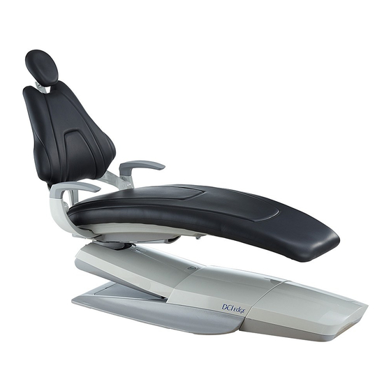
Dental chair
Hide thumbs
Also See for 5 Series:
- Instructions for use manual (26 pages) ,
- Installation instructions manual (14 pages) ,
- Instructions for use manual (8 pages)
Advertisement
Advertisement
Table of Contents

Related Manuals for DCI Edge 5 Series


Summary of Contents for DCI Edge 5 Series
- Page 1 SERIES 5 DENTAL CHAIR Installation Instructions...
-
Page 2: Overview
SERIES 5 DENTAL CHAIR Installation Instructions OVERVIEW... -
Page 3: Table Of Contents
NOTE: Take note of additional important information. Not a warning or caution. Regulatory information is delivered with DCI Edge dental equipment as mandated ELECTRICAL HAZARD: Risk of electrical shock pres- by agency requirements and can be found ent. Ensure that power is disconnected before attempt- in the accompanying Instructions for Use ing procedure. -
Page 4: Setup
SERIES 5 DENTAL CHAIR Installation Instructions SETUP TOOLS NEEDED FOR INSTALLATION • Scissors or utility knife • Allen wrench set • Socket wrench set INCLUDED HARDWARE AND COMPONENTS • Power Switch Cover PLACE THE CHAIR IN LOCATION WARNING: To prevent injury, use an as- sistant to help safely position the chair in the operatory. -
Page 5: Dimensional Layout
SERIES 5 DENTAL CHAIR Installation Instructions DIMENSIONAL LAYOUT CHAIR AND UNIT DIMENSIONS SHOWS POSITION OF POLE WHEN CHAIR IS RAISED TO FULL HEIGHT 15.0 5° 62.1 77.8 88.0 90.5 94.6 102.0 JUNCTION BOX LAYOUT 17.2” 3” 5” ACCESSORY 8” CHASE 1”... -
Page 6: Chair Preparation
SERIES 5 DENTAL CHAIR Installation Instructions CHAIR PREPARATION SHIPPING BOLT Remove the shipping bolt by unscrewing from above the seat pan casting using a 3/8” wrench. Once unscrewed, removed the bolt and related hardware from the assembly. POWER SWITCH COVER Power Switch Cover: Install the power switch cover into the opening around the power switch by snapping it firmly into place. -
Page 7: Upholstery Installation
SERIES 5 DENTAL CHAIR Installation Instructions UPHOLSTERY INSTALLATION SEAT UPHOLSTERY Center and place the seat upholstery on the seat plate so that the clips on the bottom of the seat upholstery drop into the slots of the Seat Plate. Engage the clips by pushing the seat upholstery toward the backrest. -
Page 8: Optional Quick Connect Box
SERIES 5 DENTAL CHAIR Installation Instructions OPTIONAL QUICK CONNECT BOX ATTACH BOX TO CHAIR Identify to which side of the chair the box will mount. Use two 10-32 fasteners to attach the bracket to the Quick Connection Box. Determine orienta- tion based on the side of the chair to which it will mount. -
Page 9: Adjusting Soft Limits
SERIES 5 DENTAL CHAIR Installation Instructions ADJUSTING THE CHAIR POSITION SOFT LIMITS PROGRAMMING SOFT LIIMITS Soft Limits are the software controlled position limits for the hydraulic chair movements. These can be programmed using the foot switch or any touchpad that controls chair movement. Soft limits are factory set and should only be adjusted by a technician. -
Page 10: Hydraulic System
SERIES 5 DENTAL CHAIR Installation Instructions HYDRAULIC SYSTEM HYDRAULIC SCHEMATIC HYDRAULIC CONTROL VALVE SPEED ADJUSTMENT MFG. NO. SVU2N-D24-12 MODEL: TV1 = BASE UP FLOW TV2 = BASE DOWN TV3 = BACKREST UP INC. DEC. TV4 = BACKREST DOWN To increase speed turn counterclockwise. To decrease speed turn clockwise. -
Page 11: Electrical
SERIES 5 DENTAL CHAIR Installation Instructions ELECTRICAL AUXILIARY BREAKER TRANSFORMER INPUT BREAKER LINE INPUT BREAKERS TRANSFORMER TO PCB BREAKER 9VDC OUTPUT 24VAC OUTPUT POWER INPUT110/220VAC AUXILIARY OUTPUT 110/220VAC TRANSFORMER OUTPUT 110/220VAC AUXILIARY BREAKER 32VDC OUTPUT... -
Page 12: Diagnostic Codes
SERIES 5 DENTAL CHAIR SERIES 5 DENTAL CHAIR Installation Instructions Installation Instructions DIAGNOSTIC CODES Status Codes are displayed on two 7-segment displays on the main chair control circuit board. These are visible through the clear window of the protective cover. Errors are designated with an 8 as the first digit. While there are error codes displayed, no other input or output code will be displayed. - Page 13 www.dcionline.com 305 N. Springbrook Road PN 50051 Rev. A, 04/16 800-624-2793 Newberg, OR 97132, USA...
Need help?
Do you have a question about the 5 Series and is the answer not in the manual?
Questions and answers
Part number for DCI edge series 5, wiring harness from main board to back sensor and hydraulic ram limiter for looing wire harness