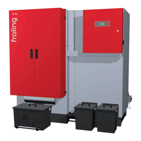
Froling TX 250 Installation Instructions Manual
Wood chip boiler
Hide thumbs
Also See for TX 250:
- Operating instructions manual (40 pages) ,
- Operating instructions manual (55 pages)
Table of Contents
Advertisement
Quick Links
Installation Instructions
Wood chip boiler TX 150-250
Translation of the original German operating instructions for technicians!
Read and follow the instructions and safety information!
Technical changes, typographical errors and omissions reserved!
M1320112_en | Edition 08/04/2013
Froling GesmbH | A-4710 Grieskirchen, Industriestraße 12 | www.froling.com
Advertisement
Table of Contents

Related Manuals for Froling TX 250


Summary of Contents for Froling TX 250
-
Page 1: Installation Instructions
Wood chip boiler TX 150-250 Translation of the original German operating instructions for technicians! Read and follow the instructions and safety information! Technical changes, typographical errors and omissions reserved! M1320112_en | Edition 08/04/2013 Froling GesmbH | A-4710 Grieskirchen, Industriestraße 12 | www.froling.com... -
Page 2: Table Of Contents
Check grate settings and install the tipping grate motor 4.5.13 Installing the fire box ash removal unit 4.5.14 Installing the switch cabinet and cable ducts 4.5.15 Installing the stoker unit 4.5.16 Installing the automatic igniter Froling GesmbH | A-4710 Grieskirchen, Industriestraße 12 | www.froling.com... - Page 3 Contents 4.5.17 Installing the actuators of the air flaps 4.5.18 Installing overpressure monitor and temperature sensor 4.5.19 Installing the underpressure measurement 4.5.20 Installing the WOS drive 4.5.21 Heat exchanger ash removal unit with ash box 4.5.22 Heat exchanger ash removal unit with ash screw (optional) 4.5.23 Installing the combustion air blower fan 4.5.24...
-
Page 4: General
General 1 General Thank you for choosing a quality product from Froling. The product features a state-of- the-art design and conforms to all currently applicable standards and testing guide‐ lines. Please read and observe the documentation provided and always keep it close to the system for reference. -
Page 5: Safety
Safety Hazard levels of warnings 2 Safety 2.1 Hazard levels of warnings This documentation uses warnings with the following hazard levels to indicate direct hazards and important safety instructions: DANGER The dangerous situation is imminent and if measures are not observed it will lead to serious injury or death. -
Page 6: Qualification Of Assembly Staff
2.3 Protective equipment for assembly staff You must ensure that staff have the protective equipment specified by accident pre‐ vention regulations. ▪ For transportation, setup and assembly: - suitable workwear - protective gloves - sturdy shoes Froling GesmbH | A-4710 Grieskirchen, Industriestraße 12 | www.froling.com... -
Page 7: Design Information
Safety Design Information 2.4 Design Information 2.4.1 Notes on standards The system must be installed and commissioned in accordance with the local fire and building regulations. The following standards and regulations should always be ob‐ served: General standards for heating systems EN 303-5 Boilers for solid fuels, manually and automatically fed combus‐... -
Page 8: Standards For Permitted Fuels
Ventilation air for the boiler room should be taken from and expelled directly outside, and the openings and air ducts should be designed to prevent weather conditions (foli‐ age, snowdrifts, etc.) from obstructing the air flow. Froling GesmbH | A-4710 Grieskirchen, Industriestraße 12 | www.froling.com... -
Page 9: Requirements For Central Heating Water
Safety Design Information Unless otherwise specified in the applicable building regulations for the boiler room, the following standards apply to the design and dimensions of the air ducts: Note on standards ÖNORM H 5170 - Construction and fire protection requirements TRVB H118 - Technical directives on fire protection/prevention 2.4.4 Requirements for central heating water The following standards and guidelines apply:... -
Page 10: Use With Storage Tank
For the correct dimensions of the storage tank and the line insulation (in accordance with ÖNORM M 7510 or guideline UZ37) please consult your installer or Froling. ⇨ See "Addresses" [page 68] 2.4.7 Chimney connection/chimney system... -
Page 11: Boiler Data For Planning The Flue Gas System
Safety Design Information Boiler data for planning the flue gas system Description Flue gas temperature at nominal load °C Flue gas temperature at partial load Flue gas mass flow - wood chips W30, 13% O kg/h 1108 Flue gas mass flow - wood chips W30, 9% O Flue gas mass flow - pellets 13% O Flue gas mass flow - pellets 9% O Required feed pressure at nominal load... -
Page 12: Technology
Boiler return connection Inch 2½ 2½ 2½ Connection of thermal discharge safety device (near boiler Inch ½ ½ ½ flow connection) Boiler drainage connection Inch ¾ ¾ ¾ Flue pipe connection Froling GesmbH | A-4710 Grieskirchen, Industriestraße 12 | www.froling.com... -
Page 13: Technical Specifications
4. Values for the types TX 200 are interpolated between the types TX 150 and TX 250, test protocol 10-UW/Wels-EX-119 and 11-UW/Wels-EX-249! - Page 14 92,1 / 92,7 93,5 / 92,0 1. Emissions values are based on dry flue gas at standard temperature and pressure (0°C, 1013 mbar) with a volume content of oxygen of 13% Froling GesmbH | A-4710 Grieskirchen, Industriestraße 12 | www.froling.com...
-
Page 15: Assembly
Assembly Transport 4 Assembly 4.1 Transport NOTICE Damage to components if handled incorrectly ❒ Follow the transport instructions on the packaging ❒ Transport components with care to avoid damage ❒ Protect the packaging against damp ❒ Operate unloading, positioning and mounting only by trained professionals! Staff has to be familiar with the handling and moving of heavy loads! (tools and lifting tools , lashing points, etc.) 4.2 Positioning... -
Page 16: Minimum Distances In The Boiler Room
Space requirement for inspection area of infeed 400 (16) (inch) Distance from heat exchanger side to wall 300 (12) Space requirement for removal of ash box 400 (16) Space requirement for inspection area of retort 400 (16) Froling GesmbH | A-4710 Grieskirchen, Industriestraße 12 | www.froling.com... -
Page 17: Mounting Steps
Assembly Mounting steps 4.5 Mounting steps 4.5.1 General information Boiler front side and boiler back side The front side is considered as operator side of the boiler. All for operation necessary elements like combustion chamber door, ash box and control box are arranged on the front side. -
Page 18: Screwing The Fire Box With The Heat Exchanger
❒ Lower the fire box, position the distance piece within the apron, lift the fire box once again and bring it completely in. Froling GesmbH | A-4710 Grieskirchen, Industriestraße 12 | www.froling.com... -
Page 19: Installing Sensor Of Thermal Discharge System
Assembly Mounting steps Adjust and fix the fire box Before fixing, the fire box has to be adjusted in the heat exchanger. Two arrestors have to be attended. Arrestor - Heat exchanger Arrestor - Main frame After positioning of the fire box in the heat exchanger: ❒... -
Page 20: Assembly Of Fireclay Blocks
➥ Make sure that two mats are placed on the side to the heat exchanger ❒ Place fireclay blocks on the ceramic fibre mats as shown ➥ Place the lateral capstone on the side to the heat exchanger with the grade downwards Froling GesmbH | A-4710 Grieskirchen, Industriestraße 12 | www.froling.com... -
Page 21: Preparation Of Flue Gas Recirculation Connection (Option)
Assembly Mounting steps 4.5.5 Preparation of flue gas recirculation connection (Option) In case of configuration of the boiler with optional flue gas recirculation (FGR), the fol‐ lowing preparation work has to be carried out: ❒ Remove the blanking plate on the fire box on the left by the infeed unit ❒... -
Page 22: Retrofitting The Wos Bar (If Necessary)
❒ Fit in the WOS shaft from the opposite and pull it through ❒ Remount the prior removed bearing bush and blind plug on the opposite side ❒ Remove the tension hook and remount it on the opposite as well Froling GesmbH | A-4710 Grieskirchen, Industriestraße 12 | www.froling.com... -
Page 23: Installing Lower Main Frame Of Insulation
Assembly Mounting steps 4.5.7 Installing lower main frame of insulation NOTICE Separate parts of the boiler are fitted with a protective film. This MUST be re‐ moved before assemby! ❒ Insert each bottom insulation below fire box and heat exchanger ❒... -
Page 24: Installing Upper Main Frame Of Insulation
❒ Screw the cable routing to the boiler laterally ❒ Place longitudinal elements on the front and the back of the boiler ❒ When putting on make sure that the lug of the cable routing threads into the frame Froling GesmbH | A-4710 Grieskirchen, Industriestraße 12 | www.froling.com... -
Page 25: Installing The Frame For The Insulating Door
Assembly Mounting steps ❒ Fix longitudinal elements to the boiler laterally ❒ At the heat exchanger side, place cross elements on longitudinal elements and bolt it together at the corners 4.5.9 Installing the frame for the insulating door ❒ Place frame element for insulating door on the front ❒... -
Page 26: Installing The Insulating Side Panels
❒ Cut the underlying insulation with a cutter along the edge and remove it ❒ Suspend the back insulating side panel for the heat exchanger at the upper and lower frame elements Froling GesmbH | A-4710 Grieskirchen, Industriestraße 12 | www.froling.com... - Page 27 ❒ Coat spaces with heat insulation mats lateral of the heat exchanger cover ❒ TX 250: Mount an additional insulation mat at the frame above the fire box ❒ Place the heat insulation mat at the upper range of the frame...
- Page 28 ❒ Screw all insulating side panels with elements of the main frame together ❒ Cover the inspection opening of the retort with insulation ❒ Mount inspection cover at the insulating side panel Froling GesmbH | A-4710 Grieskirchen, Industriestraße 12 | www.froling.com...
-
Page 29: Complete The Heat Exchanger Cover And The Combustion Chamber Door
Assembly Mounting steps 4.5.11 Complete the heat exchanger cover and the combustion chamber door ❒ Position the cover plate at the heat exchanger cover ❒ Fix the cover plate using 4 thread forming screws ❒ Mount the heat exchanger cover at the heat exchanger Installation Instructions TX 150-250 | M1320112_en... - Page 30 ❒ Fix the positioning of the key plate and check the correct locking at the limit switch when opening and closing the combustion chamber door for several times ❒ Lay the connection cable of the safety limit switch upwards through the upper opening of the frame element Froling GesmbH | A-4710 Grieskirchen, Industriestraße 12 | www.froling.com...
-
Page 31: Check Grate Settings And Install The Tipping Grate Motor
Assembly Mounting steps 4.5.12 Check grate settings and install the tipping grate motor ❒ Open the combustion chamber door and check front and rear separation in the fire ➥ Min. separation: 4mm (0.16 inch)! ❒ For corrections of the grate settings dismount the safety plate at the grate shaft ❒... - Page 32 ❒ Fix the sensor with approx. 1-2 mm (0.04-0.08 inch) separation ❒ Lay the connection cable of the sensor and the actuator on the left side upwards and lead it through the upper opening at the frame element Froling GesmbH | A-4710 Grieskirchen, Industriestraße 12 | www.froling.com...
-
Page 33: Installing The Fire Box Ash Removal Unit
Assembly Mounting steps 4.5.13 Installing the fire box ash removal unit Hexagonal bolt M8x25 Ash removal flange Plate washer Locking lever Bearing bush Chopper disk M8 Lock nut M8 ❒ Mount the locking lever at the ash removal flange as seen in the illustration above ❒... - Page 34 ❒ Mount the angle plate with 2 thread forming screws at the lug of the ash removal flange ❒ Mount the safety limit switch with each 2 fillisters M4x30, lining disks M4 and hex‐ agonal nuts M4 ➥ Do not fasten screwing yet Froling GesmbH | A-4710 Grieskirchen, Industriestraße 12 | www.froling.com...
- Page 35 Assembly Mounting steps ❒ Thread the cable of the safety limit switch through both cuttings at the frame ele‐ ment, lay them on the left side upwards and thread them through at the upper opening of the frame element ❒ Put two heat insulation mats on the ash flange ❒...
- Page 36 ❒ Slide the shaft entirely into the gear drive and rotate it until the key at the shaft aligns with the key at the gear drive, afterwards insert the fitting key Froling GesmbH | A-4710 Grieskirchen, Industriestraße 12 | www.froling.com...
-
Page 37: Installing The Switch Cabinet And Cable Ducts
Assembly Mounting steps ❒ Screw the previously removed shaft circlip onto the shaft ❒ Push the entire unit in and screw it with 4 hexagonal bolts M8x20 and lining disks M8 at the flange of the fire box 4.5.14 Installing the switch cabinet and cable ducts Depending on the design two different sizes of switch cabinets are available (600x600 mm / 600x1200 mm) (24x24 inch / 24x48 inch). - Page 38 ❒ Screw the cable duct on the back with the insulating side panel ➥ Mount cable so that the cable bushing corresponds with the one of the insulat‐ ing side panel Froling GesmbH | A-4710 Grieskirchen, Industriestraße 12 | www.froling.com...
-
Page 39: Installing The Stoker Unit
Assembly Mounting steps 4.5.15 Installing the stoker unit ❒ Remove the pre-installed adjustable foot ❒ Turn round the adjustable foot and remount it ➥ Do not fasten the screwing yet ❒ Place the stoker unit at the plug-in flange and lay in the ceramic fibre seal ❒... -
Page 40: Installing The Automatic Igniter
❒ Put the ignitor into the ignitor pipe and fix it with a double wire spring clamp ➥ Tighten the clamp gently to avoid damages ❒ Hook the base part of the cover with the adapter onto the insulating side panel Froling GesmbH | A-4710 Grieskirchen, Industriestraße 12 | www.froling.com... -
Page 41: Installing The Actuators Of The Air Flaps
Assembly Mounting steps ❒ Fix the base part of the cover on the underside with sheet metal screws ❒ Put onto the top of the cover and fix it with sheet metal screws at the side of the base part 4.5.17 Installing the actuators of the air flaps Before installing the actuators: ❒... -
Page 42: Installing Overpressure Monitor And Temperature Sensor
❒ Screw in the flange pipe of the combustion chamber temperature sensor above the overpressure sensor ❒ Loosen the clamp screw at the mating flange ❒ Insert the temperature sensor and fasten the flange bolting Froling GesmbH | A-4710 Grieskirchen, Industriestraße 12 | www.froling.com... -
Page 43: Installing The Underpressure Measurement
Assembly Mounting steps ❒ Insert the temperature sensor until it extends approx. 30 - 50 mm (1 - 2 inch) into the combustion chamber and fix this position with clamp screws ❒ Remove the cover of the junction box and connect the balancing line - green wire at the clamp with the green mark - white wire at the unmarked clamp 4.5.19 Installing the underpressure measurement... -
Page 44: Installing The Wos Drive
❒ Put on the bracket to the stud at the heat exchanger and fix it with 4 washers M8 and lock nuts M8 ❒ Mount shouldered bolts M8x20, bushing and lock nuts M8 at WOS disk as illustra‐ ❒ Insert WOS disk at the gear motor Froling GesmbH | A-4710 Grieskirchen, Industriestraße 12 | www.froling.com... - Page 45 Assembly Mounting steps ❒ Position the entire unit at the bracket so that the motor points downwards ❒ Fix the motor with 4 hexagonal bolts M8x30, washers M8 and lock nuts M8 at the bracket ❒ Insert the key and lock it ❒...
-
Page 46: Heat Exchanger Ash Removal Unit With Ash Box
❒ Set on the sealing plate and fix it with 4 hexagonal bolts M8x16 and washers M8 ❒ Mount the flange plate at the back of the heat exchanger with 4 hexagonal bolts M8x20 Froling GesmbH | A-4710 Grieskirchen, Industriestraße 12 | www.froling.com... -
Page 47: Heat Exchanger Ash Removal Unit With Ash Screw (Optional)
Assembly Mounting steps ❒ Slide in the ash box at the front of the heat exchanger and fix it with 4 star knob screws 4.5.22 Heat exchanger ash removal unit with ash screw (optional) Installing the actuator of the ash screw Heat exchanger right Heat exchanger left The following steps show the assembly of the automatic heat exchanger ash removal... - Page 48 ❒ Put the gear motor onto and fix it with 4 hexagonal bolts M8x16 ❒ Thread in the ash screw at the flange plate and gear motor and push it entirely through Froling GesmbH | A-4710 Grieskirchen, Industriestraße 12 | www.froling.com...
- Page 49 Assembly Mounting steps ❒ Put on the chain wheel at the shaft of the ash screw and insert the key ❒ Secure the key with a washer Ø30 mm (1.18 inch), a split washer M6 and an hex‐ agonal bolt M6x16 ❒...
- Page 50 Kettenräder fluchtend ausgerichtet sind ❒ Put the roller chain over both chain wheels, tighten the chain and connect it at the connecting link ❒ Secure the connecting link with a clip connector Froling GesmbH | A-4710 Grieskirchen, Industriestraße 12 | www.froling.com...
- Page 51 Assembly Mounting steps ❒ Finally put on the cover hood and fix it with 4 hexagonal bolts M8x16 at the pedes‐ ❒ Mount counterpart with captive screws Installing the ash boxes Hexagonal bolt M8x25 Ash removal flange Plate washer Locking lever Bushing Lock washer M8 Lock nut M8...
- Page 52 ❒ Mount the retainer for the safety limit switch above the ash removal flange at the insulating side panel respectively at the cover plate with sheet metal screws ➥ Place the retainer above the right corner ➥ Do not fasten screws yet Froling GesmbH | A-4710 Grieskirchen, Industriestraße 12 | www.froling.com...
- Page 53 Assembly Mounting steps ❒ Put the ash box onto the ash removal flange and place the safety limit switch at the retainer ❒ Slide key plate on the ashbox cover into the safety limit switch ❒ Fasten screwings at the retainer ❒...
-
Page 54: Installing The Combustion Air Blower Fan
4 hexagonal bolts M6x16 and washers M6 ➥ The louver has to point downwards ❒ Run the connection cable upwards and lay it to the switch cabinet through the opening in the frame element Froling GesmbH | A-4710 Grieskirchen, Industriestraße 12 | www.froling.com... -
Page 55: Installing The Stl And The Boiler Sensor
Assembly Mounting steps 4.5.24 Installing the STL and the boiler sensor ❒ Unscrew the washer at the Safety Temperature Limiter (STL) ❒ Push the STL from the behind through the frame element ❒ Fix the STL at the frame element with a locating screw ❒... -
Page 56: Installing The Id Fan
❒ Place the ID console incl. seal at the flange and fix it with each 4 hexagonal bolts M8x20 and washers M8 ❒ Level the ID console via supports ❒ Put the ID fan on the ID console as illustrated Froling GesmbH | A-4710 Grieskirchen, Industriestraße 12 | www.froling.com... -
Page 57: Installing The Fgr Air Box (Optional)
Assembly Mounting steps ❒ Mount the flue gas pipe compensator with ceramic fibre seals between ID fan and flange of the ID console ❒ Screw the included earth wire as potential equalization as illustrated on the left and the right of the flange ❒... -
Page 58: Installing The Flue Gas Recirculation Fgr (Optional)
❒ Mount the tube with flange at the flue gas collecting box ❒ Place the flue gas collecting box at the ID fan that way, that the tube points to the FRG air box at the retort Froling GesmbH | A-4710 Grieskirchen, Industriestraße 12 | www.froling.com... - Page 59 Assembly Mounting steps ❒ Fix the flue gas collecting box at the ID fan ❒ Place the flue gas pipe elbow at the tube and measure the distance between flue gas pipe elbow and FGR air box ❒ Cut the tube to the appropriate length ❒...
-
Page 60: Installing Insulating Door And Cover Plates
4.5.28 Installing insulating door and cover plates ❒ Mount the insulating doors to the door hinges at the frame element ❒ Put on the cable duct cover and fix it with self-tapping screws Froling GesmbH | A-4710 Grieskirchen, Industriestraße 12 | www.froling.com... -
Page 61: Electrical Connection
Assembly Electrical connection 4.6 Electrical connection DANGER When working on electrical components: Risk of electrocution! When work is carried out on electrical components: ❒ Only have work carried out by a qualified electrician ❒ Observe the applicable standards and regulations ➥... - Page 62 150 the cable duct is mounted below the switch cabinet ❒ Put on insulating covers on the boiler as seen at the pictures above ❒ Lay thermal discharge unit through the opening in the insulating cover and mount cover plates Froling GesmbH | A-4710 Grieskirchen, Industriestraße 12 | www.froling.com...
- Page 63 Assembly Electrical connection ❒ Apply heat insulation mat on the heat exchanger cover an put on the insulating cover Installation Instructions TX 150-250 | M1320112_en...
-
Page 64: Connecting The Thermal Discharge System
Dirt trap Pressure reducing valve 1. Required when the cold water pressure is 6 bar. It must be impossible to shut off the connection manually. Minimum cold water pressure = 2 bar Froling GesmbH | A-4710 Grieskirchen, Industriestraße 12 | www.froling.com... -
Page 65: Start-Up
Take the following precautions: ❒ Initial startup should be carried out with an authorised installer or with Froling customer services ❒ Adjust the boiler controller to the system type ❒... -
Page 66: Initial Startup
5.2.2 Heating up for the first time NOTICE If condensation escapes during the initial heat-up phase, this does not indicate a fault. ❒ Tip: If this occurs, clean up using a cleaning rag. Froling GesmbH | A-4710 Grieskirchen, Industriestraße 12 | www.froling.com... -
Page 67: Decommissioning
Decommissioning Mothballing 6 Decommissioning 6.1 Mothballing The following measures should be taken if the boiler is to remain out of service for several weeks (e.g. during the summer): ❒ Clean the boiler thoroughly and close the doors fully If the boiler is to remain out of service during the winter: ❒... -
Page 68: Appendix
7.1.1 Address of manufacturer FRÖLING Heizkessel- und Behälterbau GesmbH Industriestaße 12 A-4710 Grieskirchen AUSTRIA TEL 0043 (0)7248 606 0 FAX 0043 (0) 7248 606 600 INTERNET www.froeling com 7.1.2 Address of the installer Stamp Froling GesmbH | A-4710 Grieskirchen, Industriestraße 12 | www.froling.com...
Need help?
Do you have a question about the TX 250 and is the answer not in the manual?
Questions and answers