Table of Contents
Advertisement
Installation Instructions
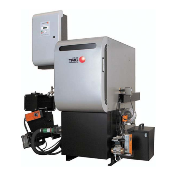
Turbomatic TMC 28-55
Be sure to read and comply with the operating instructions and safety
instructions.
Subject to technical change.
Fröling Heizkessel- und Behälterbau Ges.m.b.H, Industriestrasse 12, A-4710 Grieskirchen
Tel +43 (0) 7248 606-0 Fax +43 (0) 7248 606-600
info@froeling.com www.froeling.com
Advertisement
Table of Contents

Subscribe to Our Youtube Channel
Related Manuals for Froling Turbomatic TMC 28-55


Summary of Contents for Froling Turbomatic TMC 28-55
- Page 1 Installation Instructions Turbomatic TMC 28-55 Be sure to read and comply with the operating instructions and safety instructions. Subject to technical change. Fröling Heizkessel- und Behälterbau Ges.m.b.H, Industriestrasse 12, A-4710 Grieskirchen Tel +43 (0) 7248 606-0 Fax +43 (0) 7248 606-600...
- Page 2 Introduction Dear customer, The FRÖLING Turbomatic wood chip boiler features a state-of-the-art design that conforms to all currently applicable standards and testing guidelines. Please read and follow the installation instructions. They contain safety instructions and comprehensive information relating to transporting, setting up and assembling the boiler.
- Page 3 Introduction Guarantee Conditions Our sale and delivery conditions generally apply. These conditions have been made available to customers, and customers have been made aware of them at the time of order completion. You can also find the guarantee conditions in the enclosed guarantee certificate.
-
Page 4: Table Of Contents
1.2.5 Chimney connection/chimney system ..............9 Draught limiter....................9 Boiler data for constructing the flue gas system: ..........9 2 Technology 2.1 Turbomatic TMC 28-55 dimensions 2.2 Components and Connections 2.3 Technical specifications Test data for operation with wood chips ............12 Test data for operation with pellets .............. - Page 5 Contents 4 Initial startup / Decommissioning 4.1 Configuring the boiler 4.2 Mothballing 4.3 Disassembly 4.4 Disposal 5 Appendix 5.1 Delivery certificate -TMC 28-55 Fröling Heizkessel- und Behälterbau Ges.m.b.H, Industriestrasse 12, A-4710 Grieskirchen Page 5 Tel +43 (0) 7248 606-0 Fax +43 (0) 7248 606-600 info@froeling.com www.froeling.com M1010108_en...
-
Page 6: General Information
General Information Notes on standards 1 General Information WARNING Assembly and installation by untrained personnel! Risk of injury and damage to equipment! Only allow trained technicians (heating installers or licensed electricians) to perform set-up and installation! 1.1 Notes on Standards ÖNORM/DIN EN 303-5 Heating boilers for solid fuels, hand and automatically stocked, nominal heat output of up to 300 kW - Terminology, requirements, testing and marking... -
Page 7: Design Information
General information Design information 1.2 Design Information It is forbidden to carry out modifications to the boiler or to change or deactivate safety equipment. In addition to the documentation provided and the regulations for installation and operation of the boiler system applicable in the country in which the boiler will be operated, all fire, police, and electrical regulations must be observed. -
Page 8: Installing The Heating System / Standards
General information Notes on standards 1.2.4 Installing the heating system / Standards The following standards govern the installation of heating systems: § Applicable Standards: ÖNORM / DIN EN 12828 Heating Systems in Buildings The following prior standards still apply: Austria: - Closed systems as per ÖNORM B 8131 - Open systems as per ÖNORM B 8130 Germany:... -
Page 9: Chimney Connection/Chimney System
General information Design information 1.2.5 Chimney connection/chimney system EN 303-5 specifies that the entire flue gas system must be designed to prevent, wherever possible, damage caused by seepage, insufficient feed pressure and condensation. Please note in this respect that flue gas temperatures lower than 160K above room temperature can occur in the permitted operating range of the boiler. -
Page 10: Technology
Technology Dimensions 2 Technology 2.1 Turbomatic TMC 28-55 dimensions Pos. Description Unit TMC 28 / 35 TMC 48 / 55 Height of boiler 1425 1520 Overall height 1825 1835 Height, flue pipe connection 1525 1630 Height, outfeed connection 1275 1375... -
Page 11: Components And Connections
Technology Components and connections 2.2 Components and Connections Turbomatic Pos. Description Unit 28 / 35 48 / 55 Flue gas pipe diameter Boiler outfeed connection Connecting the Thermal Discharge Safety Device Inch Boiler return feed connection Connection for filling / emptying cock Combustion air blower fan Ash container Automatic ignition... -
Page 12: Technical Specifications
Technology Technical Specifications 2.3 Technical specifications Description Unit Rated heat output Heating efficiency range 8.4 - 28 10.5 - 35 14.4 - 48 16.5 - 55 Mains connection 400V / 50Hz fused 20A Boiler class Boiler weight Boiler water volume Permitted outfeed temperature °C Minimum return feed temperature... -
Page 13: Test Data For Operation With Pellets
Technology Technical Specifications Test data for operation with pellets Description Unit Testing institute BLT Wieselburg Test report no. 014/00 009/00 Date of issue 22.05.2000 25.04.2000 Carbon monoxide (CO) 31.00 31.52 32.48 33.00 mg/MJ Rated load 56.00 65.07 81.93 91.00 Partial load Nitrogen oxide (NOx) mg/MJ 59.00... -
Page 14: Installation
Installation Transport and setup 3 Installation 3.1 Transport The boiler comes in cardboard packaging on 3 pallets together with the chamber discharge unit. Move the boiler without jarring or jolting Follow the transport instructions on the packaging when moving the boiler. -
Page 15: Minimum Distances In The Boiler Room
Installation Transport and setup 3.2.3 Minimum distances in the boiler room The boiler should always be set up so that it is fully accessible to allow fast and easy maintenance. Observe the applicable standards and regulations when setting up the boiler. Also observe the standards pertaining to noise protection (ÖNORM H 5190 - Noise protection measures) Dimension... -
Page 16: Assembly Work
Installation Assembly work 3.3 Assembly work 3.3.1 Installing the chamber in the boiler The chamber can be installed with the stoker connection on the right or the left. Turn the chamber according to the discharge side and position on the base of the boiler Ensure that the seal is centred and in the correct position. - Page 17 Installation Assembly work Insert the ignition fan with safety guard in ignition sleeve and hand tighten the retaining screw Take care not to damage the igniter. Fit the flush-back hose to the ignition fan using a hose clamp Lay the hose to connect to the chamber and secure using hose clamp Attach insulation on grate shaft side as illustrated Ensure that the fitted screws...
- Page 18 Installation Assembly work Attach the cover on the grate shaft side Bundle the motor cables and thread them through the opening in the cover TIP: Tie the cables of the individual units to a cable harness using cable ties Fit combustion air blower fan with seal to flange Page 18 M1010108_en...
-
Page 19: Installing The Stoker
Installation Assembly work 3.3.2 Installing the stoker Assembled stoker unit with rotary valve Assembled stoker unit with burn back flap 3 pieces Seals for gravity shaft Stoker duct seal Gravity shaft nozzle 15° Screw set The following steps will guide you through the assembly process when installing a G30 stoker. -
Page 20: Installing The Burn Back Flap Drive (Only With Burn Back Flap)
Installation Assembly work Fit left and right cover plates to insulation on stoker duct Installing the burn back flap drive (only with burn back flap) Back-fire flap drive must be pre- tensioned by 5°. (delivery configuration) See included manufacturer’s documentation for how to pre- tension the drive Insert clamping piece as illustrated (90°... -
Page 21: Installing The Induced Draught Fan
Installation Assembly work Thread the torque support through the slot in the drive and tighten the burn back flap to the casing Once the drive has been unlocked the flap should fully close and the drive should be pre-tensioned < 5° See included manufacturer’s documentation for how to unlock the drive... -
Page 22: Installing The Wos Drive
Installation Assembly work 3.3.4 Installing the WOS Drive Install the WOS motor on the mounting bracket with 4 lock washers and M4x8 cheese-head bolts Attach WOS disc to motor and secure using threaded pin Position entire unit on boiler at specified holes and secure Hang the pre-tensioning spring at the mount and WOS lever... -
Page 23: Fitting The Automatic Heat Exchanger Ash Removal (Optional)
Installation Assembly work 3.3.5 Fitting the automatic heat exchanger ash removal (optional) Ash baffle (2x with Turbomatic 48-55) Flange with ash plate Ash screw Ash removal flange for ashcan Ashcan Geared motor Rubber seal and screw set shown NOTICE The components for assembling the ashcan come delivered on the left hand side of the boiler. -
Page 24: Assembly Work On Boiler
Installation Assembly work Dismantle the flange by undoing the screws Turn the flange plate and the insulating plate 180° Reassemble the flange Assembly work on boiler Fit the geared motor and seal to the flange as illustrated using the hexagonal screws provided Do not tighten the screws yet Remove the sticky tape and key-way safety device from the shaft stub on... - Page 25 Installation Assembly work Fit the previously removed key-way safety device to the shaft stub Tighten the screws on the flange and ensure that the worm is correctly aligned Insert the ash baffle into the boiler 2x guide plates with Turbomatic 48/55 Position the ash baffle inside the boiler on the front inner wall upright (see drawing below)
-
Page 26: Installing The Combustion Chamber Overpressure Sensor
Installation Assembly work 3.3.6 Installing the combustion chamber overpressure sensor If combined with a pellet suction system the combustion chamber overpressure sensor is installed in the stoker duct See assembly instructions for pellet suction system On the grate shaft side: Remove the pre-cut perforation in the centre of the insulating side panel File rough edges using a half-round... - Page 27 Installation Assembly work The bracket must point slightly upwards when not supporting a load as it will be pushed down with the weight of the switch cabinet. Attach cover plate to bracket and secure to insulating side panel Fit the cable ducts to the pre-cut holes on the insulating side panels The position of the individual cable ducts is indicated by the holes which are various distances apart.
-
Page 28: Electrical Connection
Installation Connecting the boiler 3.4 Electrical connection DANGER Working on electrical components Risk of serious injuries from electric shocks Work on electrical components should only be carried out by authorised technicians Wiring should be installed using flexible sheathed cable and dimensioned in compliance with the locally applicable standards and guidelines 3.4.1... -
Page 29: Connecting The Thermal Discharge Safety Device
Installation Connecting the boiler 3.5 Connecting the thermal discharge safety device NOTICE The thermal discharge safety device must be connected in accordance with ÖNORM/DIN EN 303-5 as shown in the following diagram. The discharge safety device must be connected to a pressurised mains water supply in such a way that it cannot be shut off. -
Page 30: Initial Startup / Decommissioning
Initial startup / decommissioning 4 Initial startup / Decommissioning 4.1 Configuring the boiler The boiler must be adjusted to the requirements of the heating system during commissioning NOTICE Optimum performance and efficient operation with low emissions can only be guaranteed if the system is set up by a qualified technician and the specified factory settings are observed. - Page 31 Appendix Delivery Certificate 5 Appendix 5.1 Delivery certificate -TMC 28-55 Customer no. Customer address: Installer: Telephone number: Turbomatic 28 kW 35 kW 48 kW 55 kW Serial number Following items checked: System operation discussed System maintenance discussed Operating principle and self-checking of safety devices discussed All technical documentation handed over (documentation, certificate of conformity, ...)
Need help?
Do you have a question about the Turbomatic TMC 28-55 and is the answer not in the manual?
Questions and answers