Table of Contents
Advertisement
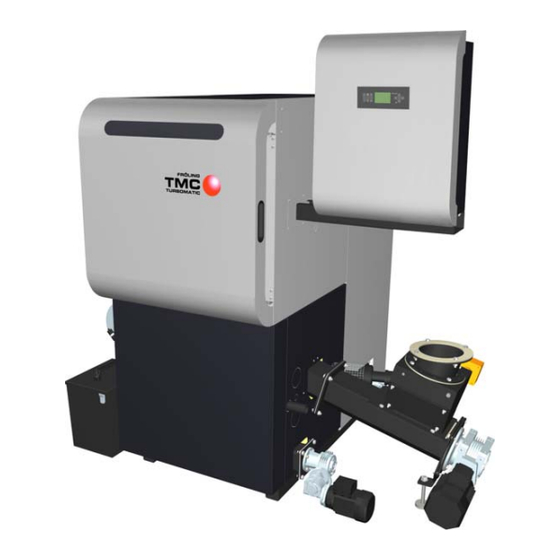
Installation Instructions
Turbomatic TMC 70-100
Be sure to read and comply with the operating instructions and safety
instructions.
Subject to technical change.
Fröling Heizkessel- und Behälterbau Ges.m.b.H, Industriestrasse 12, A-4710 Grieskirchen
Tel +43 (0) 7248 606-0 Fax +43 (0) 7248 606-600
info@froeling.com www.froeling.com
Advertisement
Table of Contents

Subscribe to Our Youtube Channel
Related Manuals for Froling Turbomatic TMC 70


Summary of Contents for Froling Turbomatic TMC 70
- Page 1 Installation Instructions Turbomatic TMC 70-100 Be sure to read and comply with the operating instructions and safety instructions. Subject to technical change. Fröling Heizkessel- und Behälterbau Ges.m.b.H, Industriestrasse 12, A-4710 Grieskirchen Tel +43 (0) 7248 606-0 Fax +43 (0) 7248 606-600...
- Page 3 Introduction Dear customer, The FRÖLING Turbomatic wood chip boiler features a state-of-the-art design that conforms to all currently applicable standards and testing guidelines. Please read and follow the installation instructions. They contain safety instructions and comprehensive information relating to transporting, setting up and assembling the boiler.
-
Page 4: Table Of Contents
1.2.5 Chimney connection/chimney system ..............9 Draught limiter....................9 Boiler data for constructing the flue gas system ..........9 2 Technology 2.1 Turbomatic TMC 70-110 dimensions 2.2 Components and connections 2.3 Technical specifications Test data for operation with wood chips ............12 Test data for operation with pellets .............. - Page 5 Contents 3.3.11 Installing the underpressure controller ............. 30 3.3.12 Completing the combustion chamber door ............31 3.3.13 Install the insulating door ................31 3.3.14 Fitting the noise protection hood and ashcans ........... 32 3.3.15 Fitting switch cabinet and cable ducts .............. 33 3.3.16 Final tests....................
-
Page 6: General Information
General Information Notes on standards 1 General Information CAUTION Assembly and installation by untrained personnel! Risk of injury and damage to equipment! The instructions and information provided in the instructions should be observed! Only trained technicians may assemble and install the system (i.e. -
Page 7: Design Information
General information Design information 1.2 Design information It is forbidden to carry out modifications to the boiler or to change or deactivate safety equipment. In addition to the documentation provided and the regulations for installation and operation of the boiler system applicable in the country in which the boiler will be operated, all fire, police, and electrical regulations must be observed. -
Page 8: Installing The Heating System / Standards
General information Notes on standards 1.2.4 Installing the heating system / Standards The following standards govern the installation of heating systems: § Applicable Standards: ÖNORM / DIN EN 12828 Heating systems in buildings The following prior standards still apply: Austria: - Closed systems as per ÖNORM B 8131 - Open systems as per ÖNORM B 8130 Germany:... -
Page 9: Chimney Connection/Chimney System
General information Design information 1.2.5 Chimney connection/chimney system EN 303-5 specifies that the entire flue gas system must be designed to prevent, wherever possible, damage caused by seepage, insufficient feed pressure and condensation. Please note in this respect that flue gas temperatures lower than 160K above room temperature can occur in the permitted operating range of the boiler. -
Page 10: Technology
Technology Dimensions 2 Technology 2.1 Turbomatic TMC 70-110 dimensions Pos. Description Unit TMC 70 / 85 / 100 Height of boiler 1740 Overall height 1980 Height, flue pipe connection 1720 Height, outfeed connection 1595 Height, return connection Height, drain Height, induced draught fan connection... -
Page 11: Components And Connections
Technology Components and Connections 2.2 Components and connections Pos. Description Unit TMC 70 / 85 / 100 Flue gas pipe diameter Boiler outfeed connection Connecting the thermal discharge safety device Inch Boiler return feed connection Connection for filling / emptying cock Combustion air blower fan 2 Ash container Automatic ignition... -
Page 12: Technical Specifications
Technology Technical specifications 2.3 Technical specifications Description Unit Rated heat output Heating efficiency range 21 - 70 25.5 - 85 30 - 100 Mains connection 400V / 50Hz fused 20A Boiler class Boiler weight 1250 1250 1250 Boiler water volume Permitted outfeed temperature °C Minimum return feed temperature... -
Page 13: Test Data For Operation With Pellets
Technology Technical specifications Test data for operation with pellets Description Unit Testing institute BLT Wieselburg Test report no. Date of issue Carbon monoxide (CO) 25.09 17.18 9.27 mg/MJ Rated load 68.09 45.18 22.27 Partial load Nitrogen oxide (NOx) 74.09 66.18 58.27 Rated load mg/MJ... -
Page 14: Installation
Installation Assembly work 3 Installation 3.1 Transport The boiler comes in cardboard packaging on 4 pallets together with the chamber delivery unit. Move the boiler without jarring or jolting Follow the transport instructions on the packaging when moving the boiler. 3.1.1 Positioning Place a fork-lift or similar lifting device with a minimum fork length of 1100 mm and an appropriate load-bearing capacity at the pallet and... -
Page 15: Minimum Distances In The Boiler Room
Installation Assembly work 3.2.3 Minimum distances in the boiler room The boiler should always be set up so that it is fully accessible to allow fast and easy maintenance. Observe the applicable standards and regulations when setting up the boiler. Also observe the standards pertaining to noise protection (ÖNORM H 5190 - Noise protection measures) Dimension... -
Page 16: Assembly Work
Installation Assembly work 3.3 Assembly work 3.3.1 Installing the chamber in the boiler If the boiler has been placed in the right position, 4 rubber supports must be inserted beneath the bottom of the boiler: Lift boiler Place 4 rubber supports on the 4 corners of the bottom of the boiler The chamber is delivered assembled and tested: Unpack the chamber and remove... -
Page 17: Installing Fitted Screws
Installation Assembly work Installing fitted screws Screw 12 fitted screws to the threaded holes in the chamber provided 3.3.2 Installing the boiler insulation Installing the insulation mounting brackets Fit 2 insulation mounting brackets on the left and right of the bottom of the boiler - 4 hexagonal screws M6x12 Fröling Heizkessel- und Behälterbau Ges.m.b.H, Industriestrasse 12, A-4710 Grieskirchen... -
Page 18: Installing The Securing Plate And Impact Plate For The Wos
Installation Assembly work Installing the securing plate and impact plate for the WOS Install the securing plate and the impact plate on threaded bolts on the left side of the boiler as shown - 2 spacer washers M8 - 2 locknuts M8 Install the buffer stop on the impact plate Installing the insulating side panels NOTICE... -
Page 19: Installing The Front Insulating Side Panels
Installation Assembly work Fit the connection profile on the left side panel with a self-tapping screw Put on the back heat insulation mat Put the side panel on at the back on the right by the insulation mounting brackets at the bottom Push the side panel onto the boiler and screw to the connecting profile with a self-tapping screw... - Page 20 Installation Assembly work Put the slit on the bottom side of the front side panel onto the insulating door mounting bracket above the chamber Insert the fitted screws of the side panel into the spring shackles of the back side panel and press on Repeat the steps for the right side panel Put a spacer washer Ø...
- Page 21 Installation Assembly work Insert the bottom insulation cover plate between the side panels Screw the bottom insulation cover plate to the side insulation cover plates on the left and right as shown Measure the diagonal length to align the side panels in parallel position Fix the position of the aligned side panels by screwing them in at the upper insulation mounting brackets...
- Page 22 Installation Assembly work Put the front insulating cover on the side panels and push back Ensure that the insulating cover pin engages in the slit of the side panels Screw the insulating cover to the side insulation cover plates on the left and right Put on the rear insulating cover Ensure that the lug goes beneath the front side panel!
-
Page 23: Insulation - Installing The Chamber
Installation Assembly work Insulation - installing the chamber Remove the protective cap from the ignition pipe Put on the insulation on the stoker side Ensure that the fitted screws engage correctly in the spring shackles. Fit the cover plate at the stoker duct with self-tapping screws Put on the insulation on the grate shaft side Ensure that the fitted screws engage correctly in the spring shackles. -
Page 24: Installing The Induced Draught Fan
Installation Assembly work 3.3.3 Installing the induced draught fan Screw in the Lambda probe with plastic bushing on the right side finger-tight Screw in the brass bushing of the flue gas sensor Push in the flue gas sensor until about 20 mm of the sensor protrudes from the brass bushing The point of the sensor should be in the middle of the flue gas pipe. -
Page 25: Installing The Wos Drive
Installation Assembly work 3.3.4 Installing the WOS drive Insert the WOS rods as shown Raise the WOS mounting bracket and push the rods through Turn the WOS rods so that the lever lies on the buffer stop Turn the WOS mounting bracket so that the linking plates of the WOS springs do not lie on the heat exchanger pipes... -
Page 26: Installing The Heat Exchanger Ash Removal Unit
Installation Assembly work 3.3.5 Installing the heat exchanger ash removal unit Put the rubber seal on the flange plate Put on the geared motor as shown and screw in with the flange plate - 4 spacer washers M8 - 4 hexagonal screws M8x20 The motor must point upwards when the flange plate is fitted. -
Page 27: Installing The Chamber Ash Removal Unit
Installation Assembly work 3.3.6 Installing the chamber ash removal unit Put the rubber seal and flange plate on the flange of the geared motor and fix - 4 hexagonal nuts M8x20 - 4 spacer washers M8 Use the ash screw with a length of 1050 mm for the chamber ash removal unit. -
Page 28: Installing The Stoker Unit
Installation Assembly work 3.3.8 Installing the stoker unit The stoker screw is pre-installed and set at the factory. Do not change the alignment of the screw! Install the supporting post at the stoker unit - 2 hexagonal nuts M16 - 2 spacer washers M16 Position the stoker unit by the chamber and put the ceramic fibre seal over the stoker screw Secure the stoker unit to the chamber flange... -
Page 29: Installing The Combustion Chamber Overpressure Sensor
Installation Assembly work Fit the flushing hose to the igniter with a hose clip Lay the flushing hose to the connection at the chamber (left, next to the stoker connection) and fix with a hose clip 3.3.10 Installing the combustion chamber overpressure sensor If combined with a pellet suction system the combustion chamber overpressure sensor is installed in the stoker duct. -
Page 30: Installing The Underpressure Controller
Installation Assembly work 3.3.11 Installing the underpressure controller Fit the hose nozzle and extension pipe together as shown and install above the stoker duct Secure the transparent tubing to the hose nozzle with a hose clamp Install the underpressure sensor cartridge as shown with self- tapping screws Connect transparent tubing with hose clip at “Minus”... -
Page 31: Completing The Combustion Chamber Door
Installation Assembly work 3.3.12 Completing the combustion chamber door Insert flange bushing into door handle Position the door handle in the hole provided Fasten the door handle in place - 1 hexagonal screw M8x30 After assembly check that the door handle operates smoothly Position the safety clamp on the door frame Fix the safety clamp at the top and bottom with rivets and locking... -
Page 32: Fitting The Noise Protection Hood And Ashcans
Installation Assembly work 3.3.14 Fitting the noise protection hood and ashcans Put the noise protection hood over the cable duct and fix with a self-tapping screw Ensure that the fitted screws engage correctly in the spring shackles. Use a self-tapping screw with a broad head! Put the ashcans on the flange of both ash removal units Page 32... -
Page 33: Fitting Switch Cabinet And Cable Ducts
Installation Assembly work 3.3.15 Fitting switch cabinet and cable ducts NOTICE Fit bracket and switch cabinet on the stoker side as the length of the cables for the individual units are measured for this side. Put 12 mm spacer washers on the threaded bolts Put the bracket for the switch cabinet on the threaded bolts and fix - 4 spacer washers M8 - 4 hexagonal nuts M8... -
Page 34: Final Tests
Installation Assembly work Fit the cable ducts to the pre-cut holes on the insulating side panels with self-tapping screws The position of the individual cable ducts is indicated by the holes which are various distances apart. Use self-tapping screws with broad heads! The vertical cable duct below the switch cabinet must be cut out horizontally (connection to horizontal duct) Fit the switch cabinet to the bracket and lay cable... -
Page 35: Electrical Connection
Installation Connecting the boiler 3.4 Electrical connection DANGER Working on electrical components Risk of serious injuries from electric shocks Work on electrical components should only be carried out by authorised technicians Wiring should be installed using flexible sheathed cable and dimensioned in compliance with the locally applicable standards and guidelines 3.4.1 Laying the cable... -
Page 36: Connecting The Thermal Discharge Safety Device
Installation Connecting the boiler 3.5 Connecting the thermal discharge safety device NOTICE The thermal discharge safety device must be connected in accordance with ÖNORM/DIN EN 303-5 as shown in the following diagram. The discharge safety device must be connected to a pressurised mains water supply in such a way that it cannot be shut off. -
Page 37: Initial Startup / Decommissioning
Initial startup / Decommissioning 4 Initial startup / Decommissioning 4.1 Configuring the boiler The boiler must be adjusted to the requirements of the heating system during commissioning NOTICE Optimum performance and efficient operation with low emissions can only be guaranteed if the system is set up by a qualified technician and the specified factory settings are observed. -
Page 38: Appendix
Appendix Manufacturer’s guarantee conditions 5 Appendix 5.1 Delivery certificate - TMC 70-110 Customer no. Customer address: Installer: Telephone number: Turbomatic 70 kW 85 kW 100 kW 110 kW Serial number Following items checked: System operation discussed System maintenance discussed Operating principle and self-checking of safety devices discussed All technical documentation handed over (documentation, certificate of conformity, ...) - Page 39 Appendix Your notes Fröling Heizkessel- und Behälterbau Ges.m.b.H, Industriestrasse 12, A-4710 Grieskirchen Page 39 Tel +43 (0) 7248 606-0 Fax +43 (0) 7248 606-600 info@froeling.com www.froeling.com M1020008_en...
Need help?
Do you have a question about the Turbomatic TMC 70 and is the answer not in the manual?
Questions and answers