Froling TX 150 Operating Instructions Manual
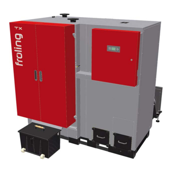
Fröling tx wood chip boiler
Hide thumbs
Also See for TX 150:
- Operating instructions manual (55 pages) ,
- Installation instructions manual (68 pages)
Table of Contents
Advertisement
Quick Links
Operating Instructions
TX 150 - 250
English version of operating instructions for operators.
Read and follow the instructions and safety instructions!
Subject to technical change.
Fröling Heizkessel- und Behälterbau Ges.m.b.H
Industriestraße 12
A-4710 Grieskirchen
Tel +43 (0) 7248 606-0
Fax +43 (0) 7248 606-600
info@froeling.com
www.froeling.com
Advertisement
Table of Contents

Related Manuals for Froling TX 150


Summary of Contents for Froling TX 150
-
Page 1: Operating Instructions
Operating Instructions TX 150 - 250 English version of operating instructions for operators. Read and follow the instructions and safety instructions! Subject to technical change. Fröling Heizkessel- und Behälterbau Ges.m.b.H Industriestraße 12 A-4710 Grieskirchen Tel +43 (0) 7248 606-0 Fax +43 (0) 7248 606-600 info@froeling.com... -
Page 2: Guarantee Conditions
Introduction Dear customer, Congratulations on choosing a quality product from FRÖLING. The FRÖLING TX wood chip boiler features a state-of-the-art design that conforms to all currently applicable standards and testing guidelines. Please read and observe the operating instructions and always keep them close to the boiler for reference. -
Page 3: Table Of Contents
Contents 1 General 1.1 Product Overview 2 Safety 2.1 Hazard levels of warnings 2.2 Pictograms used 2.3 Safety Information 2.4 Permitted uses 2.4.1 The Clean Air Act 1993 and Smoke Control Areas ..........11 2.4.2 Permitted fuels ..................... 12 Wood chips ....................12 Pellets ...................... - Page 4 Contents 3.3.5 Switching off the System ................25 4 Boiler maintenance 4.1 General information on maintenance 4.2 Inspection and cleaning 4.2.1 Inspection ....................27 Checking the thermal discharge safety device ..........27 Check safety valve ..................27 Check the system pressure ................27 Check the geared motors ................
-
Page 5: General
General Product Overview 1 General 1.1 Product Overview TX 250 only: Pos. Description Wood chip boiler - Fröling TX Switch cabinet with integrated Lambdatronic H 3200 controller Selector switch for induced draft fan Main switch: switch the power supply on and off for the entire system Control panel of the Lambdatronic H 3200 controller Status LED (operating status) - green lighting: boiler activated... - Page 6 General Product Overview Pos. Description Fuel transport unit with top gravity shaft, burn back flap or rotary valve as a burn back protection system and stoker screw for fuel transport Automatic tipping grate Combustion chamber door Heat exchanger door Efficiency Optimisation System (WOS) with turbulators Boiler outfeed connection Boiler return connection Thermal discharge safety device connection...
- Page 7 General Product Overview Pos. Description Automatic drive for heat exchanger cleaning Induced draught fan Flue gas recirculation (optional) Secondary air control with actuator drive Primary air control with actuator drive Automatic ignition Air slide for flue gas recirculation Fröling Heizkessel- und Behälterbau Ges.m.b.H Industriestraße 12 A-4710 Grieskirchen Page 7...
-
Page 8: Safety
Safety Product Overview 2 Safety 2.1 Hazard levels of warnings In these operating instructions warnings are used with the following hazard levels to indicate direct hazards and important safety instructions: D A N G E R The dangerous situation is imminent and if measures are not observed it will lead to serious injury or death. -
Page 9: Pictograms Used
Safety Pictograms used 2.2 Pictograms used The following symbols are used in the documentation and/or on the boiler to show what is required and forbidden and to give warnings. In accordance with machine guidelines, signs fitted directly in the hazard area indicate immediate hazards or safety procedures. -
Page 10: Safety Information
Safety Safety Information 2.3 Safety Information DANGER Non-permitted use! Incorrect use of the boiler can cause severe injuries and damage! The instructions and information provided in the instructions should be observed! Details on procedure for operation, maintenance and cleaning, as well as troubleshooting for the boiler are included in the individual instructions. -
Page 11: Permitted Uses
1993 including designation and supervision of smoke control areas and you can contact them for details of Clean Air Act requirements” The Froling TX 150, TX 200, TX 250 have been recommended as suitable for use in smoke control areas when burning fuels as listed under 2.4.2... -
Page 12: Permitted Fuels
Safety Permitted uses 2.4.2 Permitted fuels Wood chips Designation as per Description as per ÖNORM ÖNORM/DIN ÖNORM M 7133 M 7133 CEN/TS 14961 Water Air dried content Suitable for storage Size Fine wood chips Medium wood chips § Applicable standards: Austria: ÖNORM M 7133 or ÖNORM CEN/TS 14961 Germany:... -
Page 13: Changing The Fuel
Safety Permitted uses Changing the fuel CAUTION Incorrectly set fuel parameters: Incorrect parameter settings have a significant effect on the functioning of the boiler, and as a result this will void the guarantee. If the fuel is changed (e.g. from wood chips to pellets), the system must be reset by Fröling customer services. -
Page 14: Design Information
Safety Design Information 2.5 Design Information It is forbidden to carry out modifications to the boiler or to change or deactivate safety equipment. Always comply with all fire, building, and electrical regulations when installing or operating the boiler system, and follow the operating instructions and mandatory regulations that apply in the country in which the boiler is operated. -
Page 15: Ventilation Of The Boiler Room
For the correct dimensions of the storage tank and the line insulation (in accordance with ÖNORM M 7510 or guideline UZ37) please consult your installer or Froling. Fröling Heizkessel- und Behälterbau Ges.m.b.H Industriestraße 12... -
Page 16: Return Lift
Safety Design Information Return lift If the hot water return is below the minimum return temperature, some of the hot water outfeed will be mixed in. CAUTION Risk of dropping below dew point/condensation formation if operated without return lift. Condensation water forms an aggressive condensate when combined with combustion residue, leading to damage to the boiler. -
Page 17: Safety Devices
Safety Safety devices 2.6 Safety devices Standby button If the boiler overheats: Press the standby key ( Automatic operation is switched off and the controller follows the boiler shutdown procedure The pumps continue to run! Never use the main switch! Safety temperature limiter (back Page 18, Devices for preventing the boiler from overheating ... -
Page 18: Devices For Preventing The Boiler From Overheating
Safety Safety devices 2.6.1 Devices for preventing the boiler from overheating Thermal discharge safety device At around 100 °C a valve opens and sends cold water to the safety heat-exchanger to decrease the temperature. Safety Temperature Limiter STL Stops combustion at a max. boiler temperature of 105 °C. The pumps continue to run. -
Page 19: Residual Risks
Safety Residual risks 2.7 Residual risks WARNING Touching hot surfaces! Hot parts and the flue pipe can cause serious burns! Always wear protective gloves when working on the boiler. Only operate the boiler using the handles provided for this ... -
Page 20: Emergency Procedure
Safety Emergency procedure 2.8 Emergency procedure 2.8.1 System overheating If the system overheats in spite of the safety devices, proceed as follows: Keep all the doors on the boiler closed. Switch off the boiler using the standby key ( ... -
Page 21: Operating The System
Operating the system Assembly and initial startup 3 Operating the system 3.1 Assembly and initial startup Assembly, installation and initial startup of the boiler must only be carried out by qualified staff, and these procedures are described in the accompanying assembly instructions. ... -
Page 22: Loading Wood Chips In A Partially Emptied Store
Operating the system Filling/ refilling the store with fuel Permitted fuels Caution: Depending on the fuel and the fill level, different procedures must be followed for filling the fuel store. 3.2.1 Loading wood chips in a partially emptied store If there is still sufficient fuel in the store (the head of the stirrer is completely covered with fuel), the store can be filled: Load the fuel at the filling opening ... -
Page 23: Blowing In Pellets For A Store With Pellet Screw
Operating the system Filling/ refilling the store with fuel 3.2.3 Blowing in pellets for a store with pellet screw For systems with a pellet screw, the boiler must be in “OFF” status when the store is filled. The under-pressure from the blowing could bring smoke back into the store. -
Page 24: Blowing In Pellets For An Empty Store With Stirrer
Close all openings to the store to seal out dust Blow the fuel into the store If the storage room is completely empty and there is no residual fuel: Contact Froling before filling the store Page 24 B 067 03 11_en... -
Page 25: Heating The Boiler
Operating the system Heating the boiler 3.3 Heating the boiler 3.3.1 Switching on the system Turn the main switch on the side of the switch cabinet to the “ON” position After the system check by the controller, the system is ready for ... -
Page 26: Boiler Maintenance
Boiler maintenance General information on maintenance 4 Boiler maintenance 4.1 General information on maintenance DANGER Working on electrical components Risk of serious injuries from electric shocks Work on electrical components should only be carried out by authorised technicians WARNING Servicing when the boiler is switched on or hot: Serious injuries from automatic startup of the boiler and serious burns on hot parts and on the flue gas pipe are possible! -
Page 27: Inspection And Cleaning
Boiler maintenance Inspection and cleaning 4.2 Inspection and cleaning Regular cleaning of the boiler extends its life and is a basic requirement for smooth running based on output. So clean the boiler regularly! Recommended: When cleaning, use an ash vacuum. 4.2.1 Inspection Checking the thermal discharge safety device Check the seal of the discharge valve at regular intervals... -
Page 28: Cleaning
Boiler maintenance Inspection and cleaning 4.2.2 Cleaning Notice -> Main switch OFF Only check the ash level when “Boiler OFF” Empty the ash container retort The ash containers must be emptied at the correct intervals according to energy requirements and fuel quality. Remove the ash container cover and check the level ... -
Page 29: Empty The Heat Exchanger Ash Container
Boiler maintenance Inspection and cleaning Empty the heat exchanger ash container For heat exchanger with ashcan: Remove the star-shaped screws of the ashcan Take out the ashcan and remove the ash For heat exchanger with ash screws: Remove the ash container cover and check the level ... -
Page 30: Monthly Inspection
Boiler maintenance Inspection and cleaning 4.2.3 Monthly inspection Activate service mode For cleaning tasks in the boiler activate service mode: Press and hold the service program key ( ) for 5 seconds The controller follows the shutdown procedure and starts with the ... - Page 31 Boiler maintenance Inspection and cleaning Close the heat exchanger door and open the combustion chamber door Remove a lot of ash with a shovel Clean the step grate and sloping plates with the furnace tool Clean the side walls of the combustion chamber with the furnace tool ...
-
Page 32: Annual Inspection
Boiler maintenance Inspection and cleaning 4.2.4 Annual inspection Carry out annually, however at least after 2500 service hours! For the annual inspection: Switch off the main switch when the boiler has cooled down Clean the heat-exchanger Remove the insulated cover and open the cleaning cover ... -
Page 33: Clean The Flue Gas Recirculation (Fgr) (Optional)
Boiler maintenance Inspection and cleaning Clean the flue gas recirculation (FGR) (optional) Remove the pipe insulation from the inspection cover. Remove the inspection cover and clean the pipes of the flue gas recirculation unit with a brush After cleaning the pipes: Remove the inspection cover of the flue gas recirculation box ... -
Page 34: Clean The Induced Draught Fan
Boiler maintenance Inspection and cleaning Clean the induced draught fan Remove both cables from the induced draft fan Mark the flange position and loosen the screws on the fan flange Take out the induced draught fan and clean the blower wheel with a ... -
Page 35: Check The Combustion Chamber Overpressure Sensor
Boiler maintenance Inspection and cleaning Check the combustion chamber overpressure sensor Loosen the retaining screw. Pull the combustion chamber overpressure sensor out of the spacer pipe. Clean the sensor with a fine cloth. Check that the spacer pipe is free. ... -
Page 36: Instructions For Measuring Emissions
Boiler maintenance Instructions for measuring emissions 4.3 Instructions for measuring emissions 4.3.1 Measurement at rated load Ensure the highest possible heat consumption: Ensure that heating pumps are switched on Open mixer valves and radiator valves Set the boiler loading time to the current time Set the boiler temperature setpoint to 85°C ... -
Page 37: Maintenance Agreement / Customer Service
Boiler maintenance Maintenance agreement / Customer service 4.4 Maintenance agreement / Customer service We recommend a yearly inspection by Froling customer services or an authorised partner (third party maintenance)! Regular maintenance and servicing by a heating specialist will ensure a long, trouble-free service life for your heating system. -
Page 38: Troubleshooting
Troubleshooting General faults in power supply 5 Troubleshooting 5.1 General faults in power supply Error characteristics Cause of error Error correction Nothing is shown on the • General power failure display • FI circuit breaker or line Switch on the FI circuit breaker or ... -
Page 39: Faults With Fault Message
Troubleshooting Faults with fault message 5.3 Faults with fault message If a fault message is pending: Status LED (4.1) indicates the type of fault: - Orange flashing: warning - Red flashing: error or alarm The relevant fault message is shown on the display (4.2) ... -
Page 40: Appendix
Appendix Addresses 6 Appendix 6.1 Addresses 6.1.1 Manufacturer’s Address FRÖLING Heizkessel- und Behälterbau GesmbH Industriestraße 12 A-4710 Grieskirchen AUSTRIA TEL +43 (0)7248 606 0 FAX +43 (0)7248 606 600 E-MAIL info@froeling.com WEBSITE www.froeling.com 6.1.2 Installer’s address STAMP Page 40 B 067 03 11_en...
Need help?
Do you have a question about the TX 150 and is the answer not in the manual?
Questions and answers