
Related Manuals for Buyers 8883000


Summary of Contents for Buyers 8883000
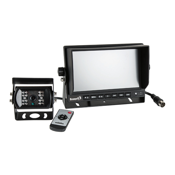
- Page 1 Phone (440) 974-8888 Fax 800-841-8003 8883000 Rear Observation System With Night Vision Camera...
-
Page 2: Table Of Contents
Table of Contents What's in the Box? ............3 Introduction ..............4 Safety Information ............5-6 Before Beginning Installation........7-8 Installation Guide ............9-10 Installing Monitor ............11-12 Installation Diagram ............13 Remote Control Diagram ..........13 Monitor Specifications ...........14 Camera Specifications ...........15 Positioning ..............16 Troubleshooting ..............17 Warranty .................18 Disclaimer ..............19... -
Page 3: What's In The Box
What’s in the Box? • (1) Color CCD Infrared Weather Resistant Camera • (1) 7" TFT LCD Color Monitor with Standard U-Bracket Mount, Pedestal Mount, Flush Mount • (1) Sun Shade • (1) 65' Camera Cable • (1) Power Harness •... -
Page 4: Introduction
Introduction Please read all of the installation instructions carefully before installing the product. Improper installation will void manufacturer’s warranty. Congratulations on purchasing a Rear Observation System With Night Vision Camera. With this manual you will be able to properly install and operate the unit. The Rear Observation System is intended to be installed as a supplement aid to your standard rear view mirror that already exists in your vehicle. -
Page 5: Safety Information
Safety Information Please read the entire manual and follow the instructions and warnings carefully. Failure to do so can cause serious damage and/or injury, including loss of life. Be sure to obey all applicable local traffic and motor vehicle regulations as it pertains to this product. Improper installation will void manufacturer’s warranty. -
Page 6: Safety Information
Safety Information • Electric shock or product malfunction may occur if this product is installed incorrectly. • Use this product within the voltage range specified. Failure to do so can cause electric shock or product malfunction. • Take special care when cleaning the monitor. •... -
Page 7: Before Beginning Installation
Before Beginning Installation Before drilling please check that no cable or wiring is on the other side of the wall. Please clamp all wires securely to reduce the possibility of them being damaged while vehicle is in use. Keep all cables away from hot or moving parts and components causing electrical interference. - Page 8 Before Beginning Installation Cable 1. Be sure to route the cable carefully. The camera cable uses aircraft grade connectors which means the camera cable can be exposed to all weather elements. Do not run the cable over sharp edges, do not kink the cable and keep away from HOT and rotating parts, such as but not limited to, exhaust systems and drive shafts.
-
Page 9: Installation Guide
Installation Guide The Power Harness • To power the system connect the power (RED) +12VDC wire to ignition power and the ground (BLACK) wire to chassis ground. • These are the only wires needed to power the entire system and all the cameras. Each camera can be seen at any time by simply pressing the power button and using the V1/2 button to toggle. - Page 10 Installation Guide • Audio: There is audio on channels 2 and 3. On CH3 the trigger wire must be energized (+12VDC) to activate the audio. On CH2 the audio is always on. • Grid-lines: The grid-lines are also carried through the CH3 wire.
-
Page 11: Installing Monitor
Standard U-Bracket Monitor Installation 1. Remove the thumb and allen screw from the monitor then remove monitor. Place bracket in desired location and fasten down with 3 screws. (See below pictures) 2. Using the thumb and allen screws put the monitor into the bracket, adjust angle, and lock it. - Page 12 Optional Monitor Installations Pedestal Mount 1. Using screws, secure pedestal bracket. (See below pictures) self-tapping screw or machine screw 2. Secondly, slide the metal buckle piece on the top of the pedestal bracket into the notch on the back of the monitor.
-
Page 13: Installation Diagram
Installation Diagram 4 Pin Connection Connect to CAM3 (CH3 normal image) Connect to CAM2 (optional camera) Connect to CAM1 (optional camera) Remote Control 1. Power 2. Switch over 3. “+” 4. Menu 5. “-” 6. Mode select... -
Page 14: Monitor Specifications
Monitor Specifications 7" monitor 1.“-” 6.Channel 2 2.Menu 7.Mode 3.“+” 8.Remote control window 4.Power 9.A/V input connector 5.Channel 1 10.Bracket knobs Screen size 7 inch Aspect ratio 16:9 Resolution 800x480 Brightness 500cdm Audio & Video 2 Ways video input (3 Ways video input optional) 2 Ways audio input 1 AV input (optional) Video System PAL &... -
Page 15: Camera Specifications
Camera Specifications Sensor 1/4 SONY Color CCD Resolution (PAL) 582(H)×510(V) pixels TV Line 420 TV Line Lens 2.8mm View angle 120° Sync System Internal Infrared distance 45ft (18pcs Infrared IR) Min illumination 0 Lux (LED ON) S/N Ratio 65dB Video output 1Vp-p 75Ω... -
Page 16: Positioning
Positioning... -
Page 17: Troubleshooting
Troubleshooting Monitor Displays Blue Screen & Displays "No Signal" • Do a hard reset, unplug all cables and power cables, leave out for 1 minute, and then re-connect. • Check to ensure that the connection to the camera is tight. •... -
Page 18: Warranty
Buyers Products Company, Inc. system after partial failure or use with improper accessories. -
Page 19: Disclaimer
In no event shall Buyers Products Company and/or its affiliates have any liability for any losses (whether direct or indirect,... - Page 20 If you have questions about this product, contact: 9049 Tyler Blvd. • Mentor, Ohio 44060 Phone (440) 974-8888 • Fax 800-841-8003 Email: support@buyersproducts.com www.buyersproducts.com IN NO EVENT SHALL SELLER OR MANUFACTURER BE LIABLE FOR ANY DIRECT OR CONSEQUENTIAL DAMAGES OF ANY NATURE, OR LOSSES OR EXPENSES RESULTING FROM ANY DEFECTIVE PRODUCT OR THE USE OF ANY PRODUCT.
Need help?
Do you have a question about the 8883000 and is the answer not in the manual?
Questions and answers