Table of Contents
Advertisement
Quick Links
I N S T A L L A T I O N I N S T R U C T I O N S
Instrucciones de instalación
Installationsanleitung
Instruções de Instalação
(Lowest position)
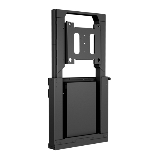
Electric Height Adjustable Wall Mount
Istruzioni di installazione
Installatie-instructies
Instructions d´installation
(Highest position)
Spanish Product Description
German Product Description
Portuguese Product Description
Italian Product Description
Dutch Product Description
French Product Description
XSD1U
Advertisement
Table of Contents

Related Manuals for LEGRAND CHIEF XSD1U


Summary of Contents for LEGRAND CHIEF XSD1U
- Page 1 I N S T A L L A T I O N I N S T R U C T I O N S Instrucciones de instalación Istruzioni di installazione Installationsanleitung Installatie-instructies Instruções de Instalação Instructions d´installation (Lowest position) (Highest position) Electric Height Adjustable Wall Mount Spanish Product Description German Product Description...
-
Page 2: Important Safety Instructions
The information contained in this document is subject dropped or damaged, or dropped into water. Return the to change without notice or obligation of any kind. Legrand mounting system to a service center for examination and makes no representation of warranty, expressed or implied, repair. - Page 3 1/2" minimum thickness plywood-backed, steel stud Responsible Party: wall covered with drywall having a maximum thickness of 5/8". Legrand AV Division Headquarters NOTE: To reduce the risk of electric shock, this furnishing has 6436 City West Parkway a polarized plug (one blade is wider than the other).
- Page 4 XSD1U Installation Instructions DIMENSIONS 0.84 21.4 [100MM] 16.00 406.4 24.00 609.6 MIN 7.94 [201.6] MAX 33.94 [862 10.13 257.2 C L to UPPER MOUNTING POINT 40.13 20.37 1019.3 517.4 26.76 679.6 12.46 316.4 26.94 684.3 14.48 367.9 PLUMB 9.98 253.4 24.12 612.7 12.83...
- Page 5 Installation Instructions XSD1U LEGEND Tighten Fastener Pencil Mark Apretar elemento de fijación Marcar con lápiz Befestigungsteil festziehen Stiftmarkierung Apertar fixador Marcar com lápis Serrare il fissaggio Segno a matita Bevestiging vastdraaien Potloodmerkteken Serrez les fixations Marquage au crayon Loosen Fastener Drill Hole Aflojar elemento de fijación Perforar...
-
Page 6: Tools Required For Installation
XSD1U Installation Instructions TOOLS REQUIRED FOR INSTALLATION 7/32" (5.3mm) - wood studs/plywood steel studs 3/8" (10mm) - concrete 1/2" (12.7mm) - standard steel studs 1/8” (included) 5/64” (included) PARTS B (1) [Wall plate] C (8) [Cable tie] A (1) [XSD1U assembly] Concrete Mounting Kit E (1) [Bluetooth®... - Page 7 Installation Instructions XSD1U PARTS - DISPLAY INTERFACE Hardware Kit Bag A Bag B Bag C TC (4) TB (4) TA (4) M4 x 12mm M4 x 25mm M4 x 20mm Bag D Bag F Bag E TF (4) TD (4) TE (4) M5 x 25mm M5 x 12mm...
-
Page 8: Assembly And Installation
XSD1U Installation Instructions Assembly And Installation The XSD1U can be to be mounted to: • a bare concrete wall with a minimum thickness of 8" (203mm): • a bare 8" x 8" x 16" (203mm x 203mm x 406mm) concrete block wall; •... - Page 9 Installation Instructions XSD1U 11. Install two 5/16 x 2 1/2” hex head cap screws (G) through two 5/16" washers (H), lower mounting holes on mount and into drilled holes on wall. (See Figure 5) CAUTION: Use proper lifting techniques and two people to install XSD1U assembly onto wall! Hang XSD1U assembly (A) onto top bracket (B) by placing the teardrop mounting holes on mount over thumb nuts on...
- Page 10 XSD1U Installation Instructions Mark hole locations for lower two mounting holes. (See Figure 9) Remove mount (A) from top bracket. 10. Drill two 3/8” holes at marked hole locations. (See Figure 9) (N) x 2 (H) x 2 (G) x 2 3/8”...
- Page 11 Installation Instructions XSD1U Site Requirements (Plywood-Backed Steel Stud) Install to plywood-backed steel stud wall using the same instructions as installing to a wood stud wall. See pages 8-9. If back side of wall is unfinished, drywall must be installed to a minimum of one stud left and right of the stud(s) being used to install the mount.
- Page 12 XSD1U Installation Instructions Site Requirements (Steel Studs without Plywood Backing) 16" (on center) Studs XSD1U Installation Location (Must be centered over two studs) If back side of wall is unfinished, drywall must be installed to a minimum of one stud left and right of the studs being used to install the mount.
- Page 13 Installation Instructions XSD1U Place top bracket (B) against wall at desired mounting Repeat Steps 4 through 7 for the other mounting hole. location 10 1/8" above the desired center of the screen. Use Steel Stud a level to ensure a level mount. (See Figure 1) Drywall Mark hole locations at each mounting location near the Plastic Cap...
- Page 14 XSD1U Installation Instructions CAUTION: Use proper lifting techniques and at least two people to install XSD1U assembly onto wall! 12. Hang XSD1U assembly (A) onto top bracket (B) by placing the teardrop mounting holes on mount over thumb nuts on bracket.
- Page 15 Installation Instructions XSD1U Height-Adjustment Setup NOTE: The control pad (P) may also be installed to the bottom edge of the display using the double-sided tape (U). If Loosen two hex head cap screws inside outer slots one half this is desired, plug the switch directly to port A1 or A2 turn each to loosen top bracket.
-
Page 16: Display Installation
XSD1U Installation Instructions Press and hold "DOWN" button for three seconds to initialize lift mechanism. (See Figure 27) 10. Press and hold "UP" button until mount reaches its maximum height. (See Figure 27) NOTE: If lifting mechanism does not function properly refer to "Troubleshooting"... - Page 17 Installation Instructions XSD1U Orient vertical mounting bracket (TR) so that mounting holes are on top and mounting slots are on bottom. (See WARNING: IMPROPER INSTALLATION CAN LEAD TO Figure 32) MOUNT FALLING CAUSING SERIOUS PERSONAL Align mounting holes in vertical mounting bracket (TR) with INJURY OR DAMAGE TO EQUIPMENT! DO NOT substitute upper and lower mounting holes in display.
- Page 18 XSD1U Installation Instructions 10. Repeat Steps 5 through 8 for Right side vertical mounting bracket using the same hole locations to align brackets horizontally. 11. Determine and mark the horizontal center position between the Left and Right TOP mounting holes in display. (See Figure 35) 12.
-
Page 19: Leveling Adjustment
Installation Instructions XSD1U 17. Make sure latching flags are in "closed" position prior to Leveling Adjustment using mount! Adjust leveling adjustment screws through access holes to IMPORTANT ! : Manufacturer recommends using cable level mount as desired +/- 3/4". (See Figure 39) ties (C) or padlock (not included) to secure the latching flags in closed position on both sides. -
Page 20: Cable Management
XSD1U Installation Instructions Cable Management IMPORTANT ! : Route cables when mount is raised to the highest position to ensure cables are installed with enough slack. Use cable clips and/or cable ties (C) to route cables as desired. (See Figure 41) Route cables through opening on bottom cover if a power box is not installed behind the mount. - Page 21 Installation Instructions XSD1U...
- Page 22 XSD1U Installation Instructions...
- Page 23 Installation Instructions XSD1U...
- Page 24 P +31 (0) 495 580 852 F +31 (0) 495 580 845 8800-003066 Rev01 Asia Pacific A Office No. 918 on 9/F, Shatin Galleria 2019 Legrand 18-24 Shan Mei Street www.legrandav.com Fotan, Shatin, Hong Kong 03/19 P 852 2145 4099...
Need help?
Do you have a question about the CHIEF XSD1U and is the answer not in the manual?
Questions and answers