Table of Contents
Advertisement
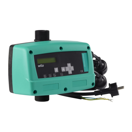
Wilo-ElectronicControl
D
Einbau- und Betriebsanleitung
GB
Installation and operating instructions
F
Notice de montage et de mise en service
NL
Inbouw- en bedieningsvoorschriften
E
Instrucciones de instalación y funcionamiento
I
Istruzioni di montaggio, uso e manutenzione
GR
Οδηγίες εγκατάστασης και λειτουργίας
RUS Инструкция по монтажу и эксплуатации
Advertisement
Table of Contents

Related Manuals for Wilo Electronic Control MT6


Summary of Contents for Wilo Electronic Control MT6
- Page 1 Wilo-ElectronicControl Einbau- und Betriebsanleitung Instrucciones de instalación y funcionamiento Installation and operating instructions Istruzioni di montaggio, uso e manutenzione Notice de montage et de mise en service Οδηγίες εγκατάστασης και λειτουργίας Inbouw- en bedieningsvoorschriften RUS Инструкция по монтажу и эксплуатации...
- Page 2 Fig. 1: Fig. 2:...
- Page 3 Fig. 3: Fig. 4:...
- Page 4 Fig. 5: Fig. 6: Fig. 7:...
-
Page 5: General Information
2.1 Indication of instructions in the operating instruction Symbols: General danger symbol Danger due to electrical voltage Note: Signals: DANGER! Acutely dangerous situation Non-observance results in death or the most serious of injuries. Installation and operating instructions Wilo-ElectronicControl... - Page 6 Works on the system or installation must only be carried out when at a standstill. All processes described in the installation and operating instruction for shutting down the system/installation must be strictly observed. WILO SE 05/2011...
-
Page 7: Transport And Storage
In case of a later installation keep the product in a dry place. Protect it against any shock and external impacts (such as moisture, frost, etc. …) 4 Intended use The ElectronicControl is a frequency inverter designed to control pumps for non aggressive clear water containing no suspended particles. Installation and operating instructions Wilo-ElectronicControl... -
Page 8: Product Information
• A tank of minimum 2 liters (to be placed at the ElectronicControl discharge side, see fig. 2, Pos. 4). • Check valve (to be placed directly at the ElectronicControl suction side, see fig. 2, Pos. 3). 5.4.2 Accessories as option • Flow switch - dry running protection. • Insulation valves. WILO SE 05/2011... -
Page 9: Description And Function
Green Inverter ON Operating mode Red led Blinking: current error Hand/Auto Fix : final error Menu Yellow Pump is working Enter Green ON : automatic mode OFF: manual mode Value setting up Value setting down Installation and operating instructions Wilo-ElectronicControl... - Page 10 10 seconds. Then the ElectronicControl shows the STANDARD display mode. Then the ElectronicControl has to be set in accordance to the pump character- istics and to the requirement of the installation, in order to warranty a safe and efficient operation. WILO SE 05/2011...
- Page 11 (bar) + flow switch detection (1 or 0) MENU SETTINGS Menu settings LANGUAGE LANGUAGE Language setting ENGLISH I. MAX. PUMP I. MAX. PUMP Nominal current set- ting as mentioned on the identification plate of the pump Installation and operating instructions Wilo-ElectronicControl...
- Page 12 (bar) + pressure setting (bar) • SERVICE : rotation frequency (Hz) + pressure setting (bar) + networkpres- sure (bar) + flow switch detection (1 or 0) HISTORIC RUNNING TIME RUNNING TIME Total pump running HOURS hours (H). WILO SE 05/2011...
- Page 13 • Follow all accident prevention regulations! • Before installation and electrical connection, switch off the product/station shall (no voltage) and be sure it cannot be switched on again without any control! • Disconnect the mains plug! Installation and operating instructions Wilo-ElectronicControl...
- Page 14 DANGER! Danger of electric shock! Do not forget the earth connection of the motor. For the electric connection of the installation to the network the ElectronicCo- ntrol plug shall be connected to the electric network. WILO SE 05/2011...
-
Page 15: Maintenance
Before a frost period it is necessary to drain the ElectronicControl. Every 6 month check the right operating of the installation: • the pressure of the bladder tank, • the tightness of the connections and • the proper closing of the valve. Installation and operating instructions Wilo-ElectronicControl... -
Page 16: High Voltage
E005 If the ElectronicControl Check the ElectronicControl HIGH VOLTAGE detects an overvoltage, it supply voltage. stops over some seconds and then starts again. WILO SE 05/2011... -
Page 17: Low Voltage
Wilo customer service point or representative. 11 Spare parts Spare parts may be ordered via local professional technicians and/or the WILO customer service. To avoid queries and order errors, please supply all data on the name plate with every order.
Need help?
Do you have a question about the Electronic Control MT6 and is the answer not in the manual?
Questions and answers