Wilo Yonos MAXO Manual
- Installation and operating instructions manual (192 pages) ,
- Installation and operating instructions manual (40 pages) ,
- Installation and operating instructions manual (160 pages)
Advertisement
General information
About these instructions
These installation and operating instructions are an integral part of the device. Read these instructions before commencing any work and keep them in an accessible place at all times. Strict adherence to these instructions is a requirement for the intended use and correct operation of the product.
All specifications and markings on the device must be observed. These installation and operating instructions correspond to the relevant version of the device and the underlying safety standards valid at the time of going to print.
The language of the original operating instructions is German. All other languages of these instructions are translations of the original operating instructions.
Transport and temporary storage
Transport inspection
Check delivery immediately for damage and integrity. Where necessary make a complaint immediately.

Damage due to incorrect handling during transport and storage!
Protect the device from moisture, frost and mechanical damage during transport and temporary storage.
Transport and storage conditions
- Store in original packaging.
- Protect against moisture and mechanical load.
- Permissible temperature range: -20°C to +70°C
- Relative humidity: maximum 95 %
Intended use
- The Wilo-Connect module Yonos MAXO is designed for external control and operating status signalling of Wilo pumps in the series:
- Wilo-Yonos MAXO (plus)
- Wilo-Yonos MAXO-D
- Wilo-Yonos MAXO-Z (plus)
 Risk of fatal electrical shock! If used improperly, there is a risk of fatal injury due to electric shock!
|
Product information
Type key
| Example: Wilo-Connect module Yonos MAXO | |
| Connect module | Function interface |
| Yonos MAXO | = Suitable for this series |
Technical data
| Instruction | Value |
| Mains voltage | 1~ 230 V +/-10% 50/60 Hz |
| Terminal cross-section mains terminals | min. 1.5 mm2, max. 2.5 mm2 |
| Terminal cross-section signal and control terminals | min. 0.25 mm2, max. 1.5 mm2 |
| Permitted ambient temperature | -20°C to +40°C |
| Degree of protection with pump | IPX4D |
| Electromagnetic compatibility | Emitted interference in acc. with: Interference resistance in acc. with: |
For further instructions see rating plate and catalogue.
Scope of delivery
- Wilo-Connect module Yonos MAXO
- 4x threaded cable gland M 16x1.5
- Installation and operating instructions
Description
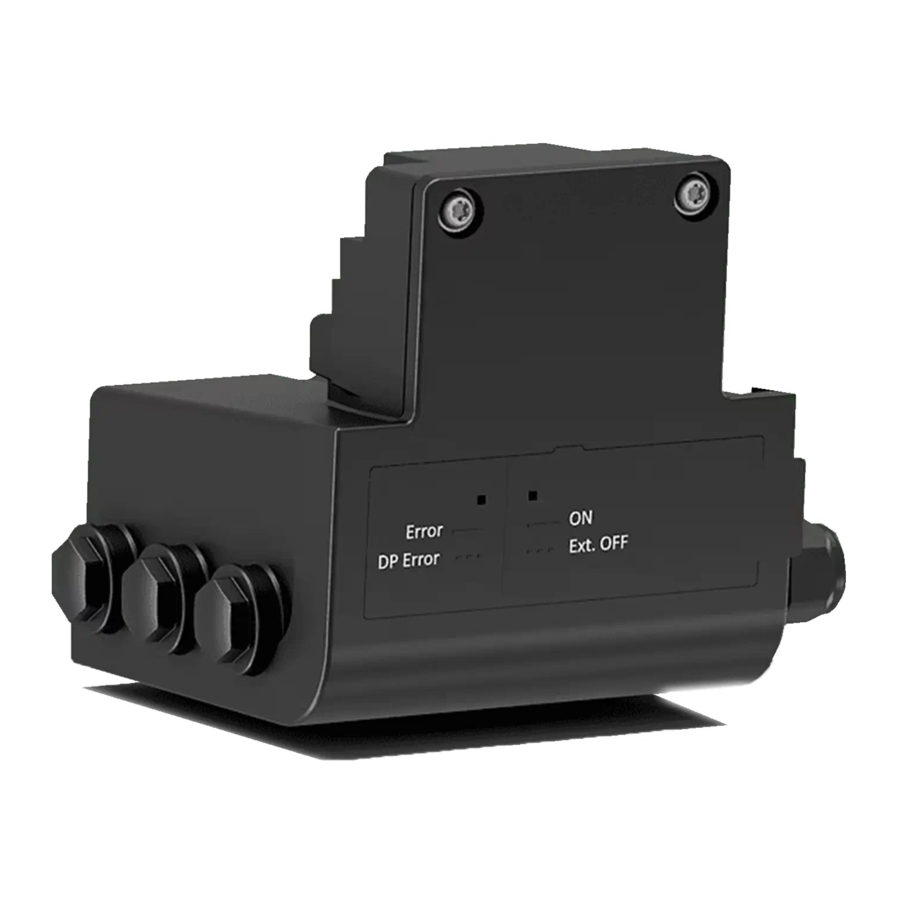
Description of Wilo-Connect module Yonos MAXO
The Wilo-Connect module Yonos MAXO extends the pump functions to include:
- SBM collective run signal as potential-free NO contact
- SSM collective fault signal as potential-free NC contact
- Control input "Overriding Off" ("Ext. Off") for potential-free NC contact
- Main/standby operation with running time-dependent switchover for twin-head pump operation.
 NOTICE
Utilisation of the Wilo-Connect module Yonos MAXO dispenses with external contactors and other switchgears.
Operating statuses
| Signal lamps and signals | Status | Meaning |
| Run signal light (green) | off | No voltage. |
| Run signal light (green) | on | Voltage applied. |
| Run signal light (green) | flashing | Control input "Ext. Off" open. |
| Fault signal light (red) | off | There is no fault. |
| Fault signal light (red) | on | A fault has occurred: Pump not running/pump faulty. |
| Fault signal light (red) | flashing | Dual-pump function not ensured/faulty. |
| Collective run signal contact | open |
|
| Collective run signal contact | closed |
|
| Collective fault signal contact | open |
|
| Collective fault signal contact | closed | There is no fault. |
Twin-head pump operation
NOTICE
Install a Wilo-Connect module for each of the two pumps.
Integrated dual-pump management with the functions:
- Main/standby operation with running time-dependent (24 h) switchover of main and standby pump. Both pumps run simultaneously at the time of pump switchover so that operation is not interrupted. Inadequate supply for example in cooling/air-conditioning system is therefore avoided.
- Fault-sensitive switchover to operational standby pump.
In case of a fault with the running pump, the system switches over to the standby pump after approx. 3 s. The master pump signals the operating status of the double pump (main and standby pump). The standby pump only signals the operating status of the standby pump.
The DIP switch 1 defines which pump is the master pump (MA) ➜ Fig. 8. "Ext. Off" of the standby pump must be closed (bridge if required).
Fig. 8:

NOTICE
If the DIP switch position "ON" = Master is selected on both modules, no standby pump is recognised for either one. Both pumps run in single pump operation according to their settings.
NOTICE
The external control command "Ext. Off" interrupts the running time counter of the switchover function.
Installation and electrical connection
- Electrical work: a qualified electrician must carry out the electrical work.
| Risk of fatal injury! Incorrect electrical connection can cause fatal electric shocks! Follow the detailed instructions for the pump series Yonos MAXO (plus), Yonos MAXO-D or Yonos MAXO-Z (plus) online: www.wilo.com/yonos-maxo-plus/om www.wilo.com/yonos-maxo/om |
 WARNING WARNINGHot surface! The entire pump can become very hot. There is a risk of burns!
|
Requirements
| Risk of fatal electrical shock!
|
- Before all work, deactivate the power supply (if necessary, SSM, SBM and twin-head pump management) and safeguard against accidental switch-on!
- Never operate the Wilo-Connect module Yonos MAXO without the module cover closed!
- Only operate the pump and Wilo-Connect module Yonos MAXO with intact components and connection cables.
NOTICE
Nationally applicable guidelines, standards and regulations as well as the requirements of local energy supply companies must be observed!
Cable requirements
Terminals are intended for rigid and flexible conductors with or without ferrules.
| Electric shock! When connecting SSM/SBM lines, ensure that the lines leading to the interface are separated! |
NOTICE
Tighten the threaded cable gland M16x1.5 at the Wilo-Connect module Yonos MAXO using a torque of 2 Nm.
Connection options
Fig. 7:

SSM and SBM can also be operated with/at non-SELV compliant connections/voltage ratings (up to 250 V AC) without this negatively influencing the remaining communication connections in the terminal room.
Ensure separate cabling in the terminal room.
Connecting
Observe all warnings in the "Electrical Connection" section!
Disconnect mains voltage before working on the module and pump!
The Wilo-Connect module Yonos MAXO is installed on the electronic module at the position of the Wilo plug.
➜ Fig. 2 to Fig. 6

- Remove the screw in the Wilo plug and disassemble the plug.
- Loosen the screws of the Connect module cover.
- Remove the module cover.
- Unscrew the required number of screw plugs (M16x1.5) with the tool.
- Screw in the threaded cable gland M16x1.5 and tighten with a torque of 2 Nm.
- Strip communication cables to the required length.
- Slide the nut of the threaded cable gland over the cable and push the cable through the inner seal ring of the threaded cable gland.
- Open spring clips if necessary, guide stripped wire ends into the terminal and close the spring clips.
- To ensure strain relief, tighten the nut of the threaded cable gland with a torque of 2 Nm.
- Insert the Wilo-Connect module Yonos MAXO into the control module of the pump and affix with a screw.
- Push the module cover forward into the grooves using the guide bars, close cover and fasten with screws.
Communication interfaces ➜ Fig. 7
Ext. Off
Remove the converter bridge before connecting the Ext. Off interface.
| Version: | Input for potential-free NC contact |
| Open circuit voltage: | max. 12 V |
| Loop current: | approx. 10 mA |
NOTICE
Ext. Off function for twin-head pump operation
The Ext. Off function of the master applies to the entire twin-head pump (main and standby pump). The Ext. Off interface of the standby pump must be bridged!
NOTICE
The connection cable at Ext. Off must be < 30 m.
Collective fault signal (SSM)
The contact of the collective fault signal (potential-free normally closed contact) can be connected to a building automation system.
| Contact load: | Permitted minimum: 12 V AC / DC, 10 mA Permitted maximum: 250 V AC, 3 A, AC1 / 30 V DC, 3 A |
Collective run signal (SBM)
The contact of the collective run signal (potential-free normally open contact) can be connected to a building automation system.
| Contact load: | Permitted minimum: 12 V AC / DC, 10 mA Permitted maximum: 250 V AC, 5 A, AC1 / 30 V DC, 5 A |
| Electric shock! Danger to life through voltage transmission, if mains and SSM pipe are led together through a 5-wire cable. | |
Dual pump management
Interface between two pumps acting together as a twin-head pump.
The role of the master can be set with the DIP switch ➜ Fig. 8.
DIP switch position "ON" = Master
| Interface: | Wilo-specific, sustained short circuit protection |
| Voltage: | max. 10 Vss |
| Frequency: | 2.4 kHz |
| Cable length: | < 3 m |
Two Wilo-Connect modules Yonos MAXO are installed for a twin-head pump.
For the integrated dual pump management function, connect terminal DP 1 of the master pump to terminal DP 1 of the standby pump ➜ Fig. 8.
The connecting cable (2 x 0.5 mm² to 2 x 1.5 mm²) is to be provided by the customer.
Observe polarity a-a and b-b.
Commissioning
Risk of damage to the Wilo-Connect module Yonos MAXO
Incorrect installation and electrical connection can pose a risk of damage to the module.
Follow the installation and operating instructions for the pump series Yonos MAXO (plus), Yonos MAXO-D or Yonos MAXO-Z (plus) during commissioning!
Activate the mains voltage after installing the Yonos MAXO Connect module.
Maintenance
The modules described in these instructions are maintenance-free.
Faults, causes, remedies
Have repairs done by qualified personnel only!
| Risk of fatal electrical shock! Ensure there are no risks arising from electrical current!
| ||
| Faults | Cause | Remedy |
| Run signal light (green) off | No voltage. | Check mains voltage. |
| Fault signal light (red) lights up | A fault has occurred: Pump not running/pump faulty. | Contact customer service. |
| Fault signal light (red) flashing |
|
|
| Collective run signal contact open |
|
|
| Collective fault signal contact open | A fault has occurred: Pump not running/pump faulty. Double pumps only:
|
|
| Dual-pump function faulty |
|
|
If the malfunction cannot be rectified, consult a specialist technician or the nearest Wilo customer service or representative location.
Spare parts
Obtain genuine spare parts only from a qualified specialist or customer service. To avoid queries and order errors, please supply all data on the rating plate with every order.
Safety
Safety information
This section contains basic information which must be adhered to during installation, operation and maintenance. Failure to follow the installation and operating instructions will result in injuries to persons, damage to the environment and the device and result in the loss of any claims for damages. Failure to follow the instructions will, for example, result in the following risks:
- Injury to persons from electrical, mechanical and bacteriological factors as well as electromagnetic fields
- Environmental damage from leakage of hazardous substances
- Damage to property
- Failure of important product functions
- Failure of required maintenance and repair procedures
The directions and safety instructions in the other sections must also be observed!
Identification of safety instructions
These installation and operating instructions set out safety instructions for preventing personal injury and damage to property, which are displayed in different ways:
- Safety instructions relating to personal injury start with a signal word and are preceded by a corresponding symbol.
- Safety instructions relating to property damage start with a signal word and are displayed without a symbol.
Signal words

Failure to follow the instructions will result in serious injury or death!

Failure to follow instructions can lead to (serious) injury!
Failure to follow instructions can lead to property damage and possible total loss.
Notice!
Useful information on handling the product
Symbols
These instructions use the following symbols:
 General danger symbol
 Danger of electric voltage
Warning – hot surfaces
Notes
Personnel qualifications
Personnel must:
- Be instructed about locally applicable regulations governing accident prevention.
- Have read and understood the installation and operating instructions.
Personnel must have the following qualifications:
- Electrical work: a qualified electrician must carry out the electrical work.
- Installation/dismantling: The technician must be trained in the use of the necessary tools and fixation materials.
- The product must be operated by persons who have been instructed on how the complete system functions.
Definition of "qualified electrician"
A qualified electrician is a person with appropriate technical education, knowledge and experience who can identify and prevent electrical hazards.
Operator responsibilities
- Have all work carried out by qualified personnel only.
- Ensure on-site guard against hot components and electrical hazards.
- Have defective gaskets and connection pipes replaced. This device can be used by children from 8 years of age as well as people with reduced physical, sensory or mental capacities or lack of experience and knowledge if they are supervised or instructed on the safe use of the device and they understand the dangers that can occur. Children are not allowed to play with the device. Cleaning and user maintenance must not be carried out by children without supervision.
Safety instructions for inspection and installation work
The operator must ensure that all inspection and installation work is carried out by authorised and qualified personnel who are also sufficiently informed from their own detailed study of the installation and operating instructions.
Work on the product/unit may only be carried out when the system is at a standstill. The procedure described in the installation and operating instructions for shutting down the product/unit must be strictly observed.
Immediately after completing work, all safety and protective devices must be put back in position and/or recommissioned.
Unauthorised modification and manufacture of spare parts
Unauthorised modification and manufacture of spare parts will impair the safety of the product/personnel and void the manufacturer's declarations regarding safety.
- Only carry out modifications to the product following consultation with the manufacturer.
- Only use original spare parts and accessories authorised by the manufacturer.
The use of other parts will absolve the manufacturer of liability for any consequences arising therefrom.
Improper use
The operational reliability of the supplied product is only guaranteed if used as intended and in accordance with the Intended use section of the installation and operating instructions. The limit values must on no account fall under or exceed those values specified in the catalogue/data sheet.
Documents / Resources
References
Download manual
Here you can download full pdf version of manual, it may contain additional safety instructions, warranty information, FCC rules, etc.
Advertisement


Need help?
Do you have a question about the Yonos MAXO and is the answer not in the manual?
Questions and answers