Table of Contents
Advertisement
Pioneering for You
Wilo-Control SC-L
de Einbau- und Betriebsanleitung
en Installation and operating instructions
fr
Notice de montage et de mise en service
es
Instrucciones de instalación y funcionamiento
it
Istruzioni di montaggio, uso e manutenzione
pt
Manual de Instalação e funcionamento
nl
Inbouw- en bedieningsvoorschriften
no Monterings- og driftsveiledning
sv
Monterings- och skötselanvisning
hr
Upute za ugradnju i uporabu
sr
Uputstvo za ugradnju i upotrebu
2537058 Ed.03/B1-05/2016 WH
Advertisement
Table of Contents
Troubleshooting

Related Manuals for Wilo Control SC-L


Summary of Contents for Wilo Control SC-L
- Page 1 Pioneering for You Wilo-Control SC-L de Einbau- und Betriebsanleitung en Installation and operating instructions Notice de montage et de mise en service Instrucciones de instalación y funcionamiento Istruzioni di montaggio, uso e manutenzione Manual de Instalação e funcionamento Inbouw- en bedieningsvoorschriften no Monterings- og driftsveiledning Monterings- och skötselanvisning...
- Page 2 Fig. 1 Fig. 2A Fig. 2B...
- Page 3 Fig. 3 Fig. 4 high water P2 ON P2 ON 3 P2 OFF 4 P1 ON P1 ON 1 all OFF P1 OFF 2 dry run Fig. 5 high water ON 1 low water 4 dry run (Ext.OFF)
-
Page 4: Table Of Contents
6.8. Factory settings Commissioning 7.1. Level control 7.2. Operation in potentially explosive areas 7.3. Activating the switchgear 7.4. Rotation control of connected three-phase AC motors 7.5. Automatic mode on the unit 7.6. Emergency operation Installation and operating instructions Wilo-Control SC-L... -
Page 5: Introduction
Terms and Conditions” apply to the warranty. 2. Safety You can find these here: www.wilo.com/legal Any deviations must be contractually agreed and This section lists all the generally applicable shall then be given priority. safety instructions and technical information. In WILO SE 05/2016 V05 DIN A4... -
Page 6: Instructions And Safety Instructions
The switchgear must be disconnected from the electricity network and An interactive menu and a rotary knob on the secured against reactivation. front of the housing are used to operate the Installation and operating instructions Wilo-Control SC-L... -
Page 7: Standards And Guidelines Used
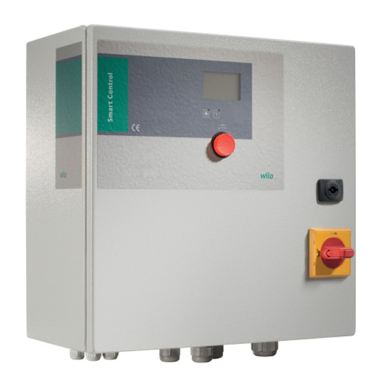
• 1x analogue input for the level sensor Fig. 1: Overview of operating components • 5x digital inputs for float switches 1 Main switch 3 Operating knob • Base-load pump ON 2 LC display 4 LED indicators • Peak-load pump(s) ON • Pumps OFF WILO SE 05/2016 V05 DIN A4... -
Page 8: Type Key
OI = outdoor installation with pedestal prevent ingress of moisture. Version for pumps and signal transmitters used • Connected power supply cables should be pro- in potentially explosive areas tected against kinking, damage, and moisture. Installation and operating instructions Wilo-Control SC-L... -
Page 9: Return Delivery
Always Mark out the 4 holes on the mounting surface and have the connection carried out by a qualified place the switching device on the floor again. electrician. Drill the holes using according to the fixation information using screws and anchors. If you are using different fixation materials, observe the information on usage! WILO SE 05/2016 V05 DIN A4... -
Page 10: Electrical Connection
When using the level sensor, the switching point must be set via the menu. A forced switch-off of the pumps always occurs, irrespective of the selected signal transmitter. 5.3.5. High water alarm The high water alarm can be via a separate float switch or via the level sensor. Installation and operating instructions Wilo-Control SC-L... - Page 11 • Star-delta activation • Contact: Set the motor protection to 0.58 x the rated • Connected: No dry run current. • Open: Dry run The maximum start-up time in star connection is 3 seconds. WILO SE 05/2016 V05 DIN A4...
-
Page 12: Operation And Function
This section contains all information on how the • Level sensor 2.5 m switchgear functions as well as information on the menu structure. • Display range: 0...2.5 m • Setting: 1 V = 0.25 m Insert the cable ends of the cable laid on-site through the threaded cable connections and secure accordingly. Installation and operating instructions Wilo-Control SC-L... -
Page 13: Operating Modes And Operation Principle
• Base-load and peak-load pump OFF • Dry-running protection • High water This enables actuation of 1 or 2 pumps. The float switch should be equipped with an NO contact i.e. on reaching or exceeding the switch- ing point, the contact is closed. WILO SE 05/2016 V05 DIN A4... -
Page 14: Menu Control And Structure
Turn main switch to ON position. Control parameters (operating mode, start/stop delays) The display lights up and outputs the latest information. The display appearance changes Communication parameters (fi eld bus) depending on the signal transmitter connected: Pump activation (activation and deactivation of the connected pumps) Installation and operating instructions Wilo-Control SC-L... - Page 15 (type, serial number etc.) Description Display Basic settings for the switchgear Fault memory Peak-load pump 3 off Service menu (can only be activated by Wilo 1.2.2.8 Value range: 0.06 to 12.42 customer service) Factory setting: 1.00 The menu structure is adapted automatically based on the signal transmitters used. Menu Delay times for activation and 1.2.2.0 is only visible for instance if a level sensor...
- Page 16 4.3.2.0 Serial number (as ticker format) 5.2.0.0 Sensor settings 4.3.3.0 Software version 4.3.4.0 Firmware version Measurement range Menu 5: Basic switchgear settings 5.2.1.0 Value range: 0 to 12.50 Factory setting: 2.50 Description Display Sensor type Values: 0-10 V, 2-10 V, 0-20 mA, 5.2.2.0 5.0.0.0 Basic settings 4-20 mA Factory setting: 4-20 mA Installation and operating instructions Wilo-Control SC-L...
- Page 17 Values: OFF, Message, Stop This menu item is only active if the optionally Pumps available module has been installed in the switch- Factory setting: Stop Pumps gear. Please contact Wilo customer service for Behaviour on activation of ther- more information and for retrofi tting. mal motor winding monitoring 5.4.8.0 and leakage detection** Menu 5.2.5.0 / Priority when dry run and high...
-
Page 18: Forced Switching Of The Pumps In Case Of Dry Run Or High Water
Menu 5.5.2.0 / SSM If you wish to reset the switchgear to these factory settings, please contact Wilo customer The required logic of the collective fault signal can be set: service. • “Fall”: negative logic (falling edge) • “Rise”: positive logic (rising edge) Installation and operating instructions Wilo-Control SC-L... -
Page 19: Commissioning
7.3. Activating the switchgear ensure that the required operating conditions are complied with. NOTE Following a power supply interruption, the switchgear will automatically start up in the last operating mode set! WILO SE 05/2016 V05 DIN A4... -
Page 20: Automatic Mode On The Unit
In case of a control failing, the individual pumps can be switched on manually. Switch off the switchgear using the main switch (“OFF” position). Installation and operating instructions Wilo-Control SC-L... -
Page 21: Disposal
10.1. Fault indication Overview of symbols: NOTE When used in sewage lifting units inside build- Error code ings or on land plots, the maintenance intervals and work shown in DIN EN 12056‐4 must be adhered to. Error icon Faults are displayed in various ways: WILO SE 05/2016 V05 DIN A4... -
Page 22: Fault Acknowledgement
10.3. Fault memory Solution: Set the separate HAND-0-AUTO switch The switchgear stores the last 16 errors in the for the pump shown to “Auto (A)”; Contact Wilo fault memory. The log uses the FiFo principle customer service (First in/First out). -
Page 23: Appendix
English APPENDIX • On-site support from Wilo customer service Pump test run • Inspection or repair of the switchgear at the factory Please note that you may be charged for some Maximum pump running time services provided by our customer service. -
Page 24: System Impedance Tables
System impedances for 3~400 V, 2-pole, star-delta starting Base-load pump: Deactivation threshold Power System impedance Connections/h ohms Base-load pump: Delay time deactivation 0.252 0.220 Peak-load pump 1: Activation threshold 0.198 Peak-load pump 2: Activation threshold 0.217 0.157 Peak-load pump 3: Activation threshold 0.130 0.113 Peak-load pump: Delay time for activation 9.0 – 11.0 0.136 9.0 – 11.0 0.098 Peak-load pump 1: Deactivation threshold 9.0 – 11.0 0.081 Installation and operating instructions Wilo-Control SC-L... -
Page 25: Spare Parts
22.0 0.033 22.0 0.027 11.3. Spare parts Spare parts can be ordered from Wilo customer service. To avoid return queries and incorrect or- ders, the serial and/or article number must always be supplied. Subject to change without prior notice. WILO SE 05/2016 V05 DIN A4... - Page 27 Vultaġġ baxx - Direttiva 2006/95/KE Smjernica o niskom naponu 2006/95/EZ Direktivi za niski napon 2006/95/EZ b'mod partikolari: primijenjene harmonizirane norme, posebno: primenjeni harmonizovani standardi, a posebno: ara l-paġna ta' qabel vidjeti prethodnu stranicu vidi prethodnu stranu WILO SE Nortkirchenstraße 100 44263 Dortmund Germany...
- Page 29 WILO SE Nortkirchenstraße 100 44263 Dortmund Germany T +49 (0)231 4102-0 F +49 (0)231 4102-7363 wilo@wilo.com Pioneering for You www.wilo.com...
Need help?
Do you have a question about the Control SC-L and is the answer not in the manual?
Questions and answers