Table of Contents
Advertisement
INTRODUCTION .......................................................................................................................... 1
A. SYSTEM OVERVIEW ......................................................................................................................................... 1
B . SWITCH OVERVIEW ......................................................................................................................................... 1
ON OFF ............................................................................................................................................................................... 2
A L A R M ............................................................................................................................................................................... 2
SETUP .................................................................................................................................................................................. 2
MIN AVG MAX SCAN ................................................................................................................................................. 2
SELECT ROW ................................................................................................................................................................... 2
SELECT ............................................................................................................................................................................... 2
S E T ....................................................................................................................................................................................... 2
START STOP RESET .................................................................................................................................................... 3
BACK ................................................................................................................................................................................... 3
OPERATE 1 ....................................................................................................................................................................... 3
OPERATE 2 ....................................................................................................................................................................... 3
OPERATE 3 ....................................................................................................................................................................... 3
SYSTEM INSTALLATION ......................................................................................................... 5
A. CONSOLE MOUNTING ..................................................................................................................................... 5
B . CONSOLE HARNESS INSTALLATION ....................................................................................................... 6
C. IMPLEMENT HARNESS/MODULE/SENSORS .......................................................................................... 9
SETUP MODE ............................................................................................................................... 19
A. SETUP CONSTANTS ............................................................................................................................................ 19
1 .
Population Hi Limit ....................................................................................................................................................... 2 0
2 .
Population Lo Limit ....................................................................................................................................................... 2 0
3 .
Row Width ........................................................................................................................................................................ 2 1
4 .
Implement Width ............................................................................................................................................................ 2 1
5 .
Ground Speed Source .................................................................................................................................................... 2 2
6 .
Distance Calibration ...................................................................................................................................................... 2 2
7 .
Automatic Configuration .............................................................................................................................................. 2 3
8 .
Split Row Configuration ............................................................................................................................................... 2 4
9 .
Number of Seed Modules ............................................................................................................................................. 2 5
1 0 . Number of Seed Sensors Per Module ....................................................................................................................... 2 5
1 1 . Row Status ......................................................................................................................................................................... 2 6
1 2 . Total Number Of Rows Configured ......................................................................................................................... 2 7
1 3 . Number of Fan Speed Sensors .................................................................................................................................... 2 7
1 4 . Fan Speed Sensor Constant .......................................................................................................................................... 2 8
1 5 . Fan Speed Sensor Hi Limit .......................................................................................................................................... 2 8
1 6 . Fan Speed Sensor Lo Limit .......................................................................................................................................... 2 9
1 7 . Number of Shaft Speed Sensors .................................................................................................................................. 2 9
1 8 . Shaft Speed Sensor Constant ....................................................................................................................................... 3 0
1 9 . Shaft Speed Sensor Hi Limit ....................................................................................................................................... 3 0
2 0 . Shaft Speed Sensor Lo Limit ....................................................................................................................................... 3 1
2 1 . Number of Hopper Level Sensors .............................................................................................................................. 3 1
2 2 . Number of Pressure Sensors ........................................................................................................................................ 3 2
2 3 . Pressure Sensor Hi Limit .............................................................................................................................................. 3 2
2 4 . Pressure Sensor Lo Limit .............................................................................................................................................. 3 3
2 5 . Blockage Mode Configuration .................................................................................................................................... 3 3
2 6 . Population Filter .............................................................................................................................................................. 3 4
2 7 . Population Scaling Factor ............................................................................................................................................. 3 4
2 8 . Sensor/Module Self-Test ............................................................................................................................................... 3 5
2 9 English/Metric Units ...................................................................................................................................................... 3 6
B.CUSTOMER SETUP CONSTANTS ..................................................................................................................... 36
1 .
Boot Version Number ................................................................................................................................................... 3 6
2 .
Flash Version Number .................................................................................................................................................. 3 7
CONTENTS
Advertisement
Table of Contents

Related Manuals for Dickey-John Seed Manager SE


Summary of Contents for Dickey-John Seed Manager SE
-
Page 1: Table Of Contents
CONTENTS INTRODUCTION .......................... 1 A. SYSTEM OVERVIEW ............................1 B . SWITCH OVERVIEW ............................1 ON OFF ....................................2 A L A R M ....................................2 SETUP ....................................2 MIN AVG MAX SCAN ..............................2 SELECT ROW ................................... 2 SELECT ....................................2 S E T ....................................... - Page 2 OPERATE MODE ........................39 A. OPERATE MODE .............................. 39 B . RUN HOURS ............................... 39 C. POPULATION ..............................40 1 . Population SCAN ................................ 4 1 2 . Population MIN AVG MAX ........................... 4 1 3 . Population SELECT ROW ............................4 2 4 .
-
Page 3: Introduction
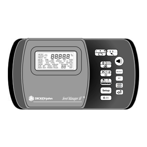
Ground Speed input. It is shown in italicized print. An overview of compatible with DICKEY-john Standard the switches follows: and Hi-Rate seed sensors and Recon Flow sensors. The monitor will store all... -
Page 4: On Off
OPERATOR'S MANUAL ON OFF MIN AVG MAX SCAN Pressing this switch applies power to the This switch is pressed to toggle between monitor. Upon power up, the monitor the MIN AVG MAX and SCAN options performs internal diagnostic checks, for Population and Spacing. illuminates all segments of the LCD, sounds the alarm, and determines what sensors are connected to the system. -
Page 5: Start Stop Reset
OPERATOR'S MANUAL START l l l l STOP RESET OPERATE 1 START STOP RESET This switch is used to select Population, This switch is used in multiple modes for Spacing, or Ground Speed Mode. multiple purposes. Some examples are Pressing the switch repeatedly, will as follow: It is used in the Operate change to the next mode. - Page 6 OPERATOR'S MANUAL Dj SEED MANAGER® SE PLANTER MONITOR 4/ INTRODUCTION BENCHMARK Series® 11001-1218-200112 Rev A...
-
Page 7: System Installation
OPERATOR'S MANUAL SYSTEM INSTALLATION A . CONSOLE drill two 9/32 inch ( 7 mm ) holes. An MOUNTING alternate mounting method, which allows the console to swivel, requires drilling the The console should be mounted inside center bracket hole only. the tractor cab in a location accessible to the operator but does not obstruct the driving view. -
Page 8: Console Harness Installation
OPERATOR'S MANUAL B . CONSOLE HARNESS For systems that contain a J2 connector, a INSTALLATION separate accessory harness will contain a RS-232 connector for PC/GPS applica- The J1 connector on the back of the tions. console connects all input and output signals to the Seed Manager®... - Page 9 OPERATOR'S MANUAL side of the tractor opposite the alternator harness consist of two wires, each and spark plugs. Locate the harness to terminated with a ring terminal. prevent being pinched, cut, or stepped on and secure it with wire ties. Before making the battery connections, determine the tractor battery arrange- STEP 2...
- Page 10 OPERATOR'S MANUAL Figure 4 12 Volt Battery Source Connections Vehicle Ground Power Black Power Cable Cable Black Vehicle Ground Figure 5 24 Volt Battery Source Connections Figure 6 Negative or Positive Sources Connections 8/ INSTALLATION Dj SEED MANAGER® SE PLANTER MONITOR BENCHMARK Series®...
-
Page 11: Implement Harness/Module/Sensors
OPERATOR'S MANUAL C. IMPLEMENT 3. No more than three Material Flow HARNESS / Modules can be connected to P1 or P2. MODULES / 4. Any combination of 12 Row or 16 Row SENSORS Material Flow Modules may be used. The Seed Manager® SE system uses any combination of three basic module types, The order in which the Material Flow each with their own specific harness... - Page 12 OPERATOR'S MANUAL In this four module setup, two modules are connected to P1 and two to P2. Figure 6A Four module setup In this three module setup, all modules are connected to P1. Figure 6B Three module setup In this three module setup, one module is connected to P1 and two are connected to Figure 6C Three module setup 10/ INSTALLATION...
- Page 13 OPERATOR'S MANUAL In this two module configuration, one module is connected to both P1 and P2. Figure 6D Two module setup In this five module configuration, three modules are connected to P1 and two are connected to P2. Figure 6E Five module setup As the previous examples show, b1 is always identified as the LAST module connected to P1.
- Page 14 OPERATOR'S MANUAL When connecting sensors to the Material Flow Modules, the following requirement must be observed: 1. All seed sensors installed on a Material Flow Module must be connected sequential- ly starting with Row 1 as shown below. Figure 6F Correct Install CORRECT RS-485 IN...
- Page 15 OPERATOR'S MANUAL There can be no skips in the row inputs on a Material Flow Module. The following shows the previous eight row module setup incorrectly: Figure 6H Incorrect Install INCORRECT RS-485 IN RS-485 OUT Follow the same examples on all Material Flow Modules used in the system. When correctly connected, row 1 sensor should be connected to the Row 1 input on b1.
- Page 16 OPERATOR'S MANUAL When hopper level sensors are connected to a Shaft Speed Module, they are num- bered relative to the position of the Shaft Speed Module on the bus. If the Shaft Speed Module is connected to the RS-485 Out of b1, the numbering of the hopper sensors starts with this module, then continues with any hopper sensors connected to b1, b2, etc.
- Page 17 OPERATOR'S MANUAL Figure 6K Dj SEED MANAGER® SE PLANTER MONITOR INSTALLATION/ 15 BENCHMARK Series® 11001-1218-200112 Rev A...
- Page 18 OPERATOR'S MANUAL Figure 6L 12 Row Harness Figure 6M 16 Row Harness 16/ INSTALLATION Dj SEED MANAGER® SE PLANTER MONITOR BENCHMARK Series® 11001-1218-200112 Rev A...
- Page 19 OPERATOR'S MANUAL Figure 6N Shaft Speed Module Harness Figure 6O RS-485 Extension Harness Dj SEED MANAGER® SE PLANTER MONITOR INSTALLATION/ 17 BENCHMARK Series® 11001-1218-200112 Rev A...
- Page 20 OPERATOR'S MANUAL 18/ INSTALLATION Dj SEED MANAGER® SE PLANTER MONITOR BENCHMARK Series® 11001-1218-200112 Rev A...
-
Page 21: Setup Mode
OPERATOR'S MANUAL SETUP MODE A . SETUP Pressing START STOP RESET zeroes CONSTANTS the digit. Each depression of the The Setup Mode is used to enter the SELECT switch makes the next digit to implement configuration constants, the right the selected digit. which are listed in Figure 7, in the order of their presentation. -
Page 22: Population Hi Limit
OPERATOR'S MANUAL Figure 8 POPULATION HI LIMIT Display (hectare), the alarm sounds, as indicated To exit the Setup Mode, press any of the under the heading ALARMS, POPU- three Operate switches. Exiting automat- LATION HI LIMIT WARNING. ically stores the last constant changed. Figure 8 shows the display for a limit of 176,000 seeds/acre. -
Page 23: Row Width
OPERATOR'S MANUAL Figure 10 ROW WIDTH Display 3. Row Width 4. Implement Width This is the distance in inches (centime- This is the seeding width of the imple- ters) between rows, with a resolution of ment in inches (centimeters) with a 0.1. -
Page 24: Ground Speed Source
OPERATOR'S MANUAL Figure 12 Ground Speed Sensor Type Display 5. Ground Speed Source 6. Distance Calibration Pressing the Set switch causes the lower The Distance Calibration constant is the right display to toggle between “d1”, “r1”, number of pulses generated by the or “d2”. -
Page 25: Automatic Configuration
OPERATOR'S MANUAL To perform the Distance Calibration: The TEST message flashes while the Automatic Configuration is running. STEP 1 Configuration is complete when the TEST Carefully measure a 400 foot (122 meter) message disappears. The Automatic course, plainly marking the start and finish Configuration will automatically detect how points. -
Page 26: Split Row Configuration
OPERATOR'S MANUAL 8. Split Row Configuration selected, all of the rows are automatically For users that utilize split, twin, or skip turned ON or OFF according to the row type seeding implements, this feature pattern. The user can still edit individual will allow easy configuration for setting rows in the Row Configuration Screen, up the correct row pattern that is used. -
Page 27: Number Of Seed Modules
OPERATOR'S MANUAL Figure 16 Pattern Select Display 9. Number of Seed Modules 10. Number of Seed Sensors Per This is the actual number of Seed Module Modules that are connected to the For each Seed Module that is configured system. Note: This does not include the on the previous Setup Screen, there will Shaft Speed Module if one is available be a Number of Seed Sensors Per... -
Page 28: 1 . Row Status
OPERATOR'S MANUAL Figure 18 Sensors Per Module Display ter will be checked as part of the Sensor/ The display initially shows the messages Module Self-Test and Error codes will be SETUP, ROW, 1, and the status of row generated if this value does not match the 1. -
Page 29: 2 . Total Number Of Rows Configured
OPERATOR'S MANUAL Figure 20 Rows Configured Display 13. Number of Fan Speed Sensors 12. Total Number Of Rows This is the actual number of Fan Speed Configured Sensors that are connected to a Shaft This parameter is used to calculate Speed Module on the system. -
Page 30: 4 . Fan Speed Sensor Constant
OPERATOR'S MANUAL Figure 22 Fan Speed Constant Display 14. Fan Speed Sensor Constant 15. Fan Speed Sensor Hi Limit The Fan Speed Constant is the number This constant is the highest Fan Speed of pulses the Fan Speed Sensor gener- (RPM) allowed before sounding a ates in one revolution of the monitored warning alarm. -
Page 31: 7 . Number Of Shaft Speed Sensors
OPERATOR'S MANUAL Figure 24 Lo Limit Fan Speed Display 16. Fan Speed Sensor Lo Limit 17. Number of Shaft Speed This constant is the lowest Fan Speed Sensors (RPM) allowed before sounding a This is the actual number of Shaft Speed warning alarm. -
Page 32: 8 . Shaft Speed Sensor Constant
OPERATOR'S MANUAL Figure 26 Shaft Speed Constant Display 18. Shaft Speed Sensor Constant 19. Shaft Speed Sensor Hi Limit The Shaft Speed Constant is the number This constant is the highest Shaft Speed of pulses the Shaft Speed Sensor (RPM) allowed before sounding a generates in one revolution of the warning alarm. -
Page 33: 1 . Number Of Hopper Level Sensors
OPERATOR'S MANUAL Figure 28 Lo Limit Shaft Speed Display 20. Shaft Speed Sensor Lo Limit 21. Number of Hopper Level This constant is the lowest Shaft Speed Sensors (RPM) allowed before sounding a This is the actual number of Hopper warning alarm. -
Page 34: 2 . Number Of Pressure Sensors
OPERATOR'S MANUAL Figure 30 Pressure Sensor Display 22. Number of Pressure Sensors the Number of Pressure Sensors has a This is the actual number of Pressure value other than 0. Setting the Pressure Sensors that are connected to a Shaft Sensor Hi Limit will cause the audible Speed Module on the system. -
Page 35: 5 . Blockage Mode Configuration
OPERATOR'S MANUAL Figure 32 Lo Limit Pressure Display 24. Pressure Sensor Lo Limit will toggle the status of the warning The Pressure Sensor Lo Limit Warning between ON and OFF. Figure 32 shows is entered in oz/in (kPa). The Hi and a Pressure Sensor Lo Limit of 3.8 with Lo warning limits are accessible only if the warning disabled. -
Page 36: 6 . Population Filter
OPERATOR'S MANUAL Figure 34 Blockage Mode Display In all modes Row failures will be tions. The filter values range from 0 to displayed according to the details in the 99, with 0 having no filtering effect, and ALARMS section of this document. 99 being the maximum filtering value. -
Page 37: 8 . Sensor/Module Self-Test
OPERATOR'S MANUAL Figure 36 Population Scaling Display SELECT switches to adjust to the rows), or show FAILED and display the desired population scaling factor. Figure appropriate error code(s). If multiple 36 shows a Population Scaling of 105%. errors exist, the E in the error code will be flashing. -
Page 38: 9 English/Metric Units
Units Selection Display 29. English/Metric Units 1. Boot Version Number The user selects the system of units with DICKEY-john’s Service Department this constant. The SET switch is used to may request the customer to observe and toggle between English and Metric units. -
Page 39: Flash Version Number
Figure 39 Boot Number 2. Flash Version Number numeric display. Record this number, DICKEY-john’s Service Department then press and release the SELECT may request the customer to observe and switch to step to the “F2”, “F3”, and “Fc” record the four (4) different 4-digit numbers, recording each 4-digit number numbers (to identify the “flash memory”... - Page 40 OPERATOR'S MANUAL 38/ SETUP Dj SEED MANAGER® SE PLANTER MONITOR BENCHMARK Series® 11001-1218-200112 Rev A...
-
Page 41: Operate Mode
OPERATOR'S MANUAL OPERATE MODE A. OPERATE MODE B. RUN HOURS Performance of the following Operate This is defined as the total number of Mode functions assumes the console has accumulated hours, in 0.1 hour incre- been properly installed and setup as ments, the console has been powered. -
Page 42: Population
OPERATOR'S MANUAL Figure 42 Run Hours Display desired function. Otherwise the by pressing the OPERATE 1 switch until Population function is automatically the POPULATION message appears selected. To zero the accumulated Run on the display. Only the seed rows that Hours, press the START STOP have their row status set to ON will be RESET switch for one (1) second while... -
Page 43: Population Scan
OPERATOR'S MANUAL Figure 43 Population SCAN Display 1. Population Scan 2. Population Min Avg Max This mode will display the population of This mode will display the seeding row each valid row for two (2) seconds, then with the minimum population, the advances to the next row. -
Page 44: Population Select Row
OPERATOR'S MANUAL Figure 45 Population SELECT ROW Display 3. Population Select Row 4. Seed Spacing Depressing the SELECT ROW switch This is the calculated average spacing while in either Population Scan or between seeds in the furrow, in inches Population Min Avg Max freezes the (centimeters). -
Page 45: Ground Speed
OPERATOR'S MANUAL Figure 47 Ground Speed Display 5. Ground Speed 6. Fan Speed This is the ground speed in MPH (Km/ This is the rotational speed of any Fan h), with 0.1 resolution, as measured by the user wishes to monitor. A Hall the ground speed sensor. -
Page 46: Shaft Speed
OPERATOR'S MANUAL Figure 49 Shaft Speed Display 8. Pressure 7. Shaft Speed This is the pressure in oz/in (kPa), as This is the rotational speed of any shaft measured by a pressure sensor, to a the user wishes to monitor. A Hall Effect type sensor senses a multi-toothed resolution of 0.1 oz/in (kPa). -
Page 47: Area Accumulator
OPERATOR'S MANUAL Figure 51 Area Accumulator 1 Display 9. Area Accumulator Figure 51 shows Area Accumulator 1 with 1674.3 acres. Area Accumulator 1 and 2 are intended to be used as field area accumulators, displaying acres with 0.1 resolution 10. Seed Count (hectares with 0.01 resolution). -
Page 48: 0 . Seed Count
OPERATOR'S MANUAL Figure 52 Seed Count Display Any other Operate Mode function can Any other Operate Mode function can be selected while Seed Count is running be selected while Distance Accumulator without affecting the actual seed counts. is running without affecting the actual Figure 52 shows a stopped seed counter distance accumulation. - Page 49 OPERATOR'S MANUAL Figure 53 Distance Accumulator Display accumulate only when the implement is The alarm will sound momentarily and a down. The Distance Accumulator E00 (No seed sensors connected) error function is independent of the lift switch code will be displayed. Press the status.
- Page 50 OPERATOR'S MANUAL 48/ OPERATE Dj SEED MANAGER® SE PLANTER MONITOR BENCHMARK Series® 11001-1218-200112 Rev A...
-
Page 51: Alarms
OPERATOR'S MANUAL ALARMS Unless indicated below, when an alarm Priority levels are assigned to the Seed Manager® SE alarms as shown in Figure condition occurs, the console exits the 54, with level one (1) being the highest. If current Operate Mode function to two alarm conditions are detected at the display the alarm. -
Page 52: All Rows Failed
OPERATOR'S MANUAL longer the alarm is sounded. Unless the failure condition ceases or is otherwise indicated, a “failure” alarm acknowledged by pressing the ALARM sounds continuously (not beeping) until switch. Figure 54 Alarm Levels Alarms Chart Alarm Mode Priority Level All Rows Failed Row Failed Distance Sensor Failed... - Page 53 OPERATOR'S MANUAL acknowledged, the only functions that are 1. All Rows Failed This occurs at the end of each row when available are in the SETUP MODE the implement is lifted from the ground. (reference the SETUP MODE chapter for more information). The alarm sounds continuously for three (3) seconds, the ROWS and FAILED messages appear, and the row...
-
Page 54: Population Hi Limit Warning 5
OPERATOR'S MANUAL Figure 56 POPULATION HI LIMIT Warning Display POPULATION LIMIT speed of 5.3 MPH entered. The manual ground speed. However, it is operator next presses the desired very important to remember to immedi- Operate Mode switch to return to ately repeat the SETUP MODE seeding. -
Page 55: Fan Speed Lo Limit Warning
OPERATOR'S MANUAL Figure 57 POPULATION LO LIMIT Warning Display POPULATION LO LIMIT 6. Fan Speed Hi Limit Warning 5. Population Lo Limit Warning This occurs when any fan speed exceeds This occurs when any row population the value entered for Fan Speed Hi falls below the value entered for Limit in the SETUP MODE. -
Page 56: Shaft Speed Hi Limit Warning
OPERATOR'S MANUAL Figure 59 FAN SPEED LO LIMIT Warning Display 7. Fan Speed Lo Limit Warning 8. Shaft Speed Hi Limit Warning This occurs when any fan speed falls This occurs when any shaft speed below the value entered for Fan Speed exceeds the value entered for Shaft Lo Limit in the SETUP MODE. -
Page 57: Shaft Speed Lo Limit Warning
OPERATOR'S MANUAL Figure 61 SHAFT SPEED LO LIMIT Warning Display 10. Pressure Hi Limit Warning 9. Shaft Speed Lo Limit Warning This occurs when any pressure input This occurs when any shaft speed falls exceeds the value entered for Pressure below the value entered for Shaft Speed Hi Limit in the SETUP MODE. -
Page 58: 1 . Pressure Lo Limit Warning
OPERATOR'S MANUAL Figure 63 PRESSURE LO LIMIT Warning Display 11. Pressure Lo Limit Warning 12. Hopper Lo Warning This occurs when any pressure input This occurs when any hopper input falls below the value entered for signals a low material level. The alarm Pressure Lo Limit in the SETUP sounds continuously and the hopper MODE. -
Page 59: 3 . Battery Voltage Warning
OPERATOR'S MANUAL Figure 65 BATTERY VOLTAGE Warning Display 13. Battery Voltage Warning battery symbol appears. The battery To ensure accurate operation of the symbol remains on the display until the sensors and modules, the voltage to the low battery condition ceases. The console must be at least eleven (11) volts. - Page 60 OPERATOR'S MANUAL 58/ ALARM Dj SEED MANAGER® SE PLANTER MONITOR BENCHMARK Series® 11001-1218-200112 Rev A...
-
Page 61: Self Test Error Codes
OPERATOR'S MANUAL SELF TEST ERROR CODES The Seed Manager® SE Console appropriate error codes that were performs a Self Test upon power up detected. Figure 66 shows a complete list and when commanded by the user in of all error codes that can be displayed. See the TROUBLESHOOTING SETUP MODE. - Page 62 OPERATOR'S MANUAL 60/ ERROR CODES Dj SEED MANAGER® SE PLANTER MONITOR BENCHMARK Series® 11001-1218-200112 Rev A...
-
Page 63: Troubleshooting
Corrective Action 1. Check console fuse. If blown, replace with a seven one-half (7.5) Amp, type AGC fuse. If it blows again, contact DICKEY-john Technical Support to replace console. See inside, back cover of this manual for phone number. 2. Clean and tighten battery connections 3. -
Page 64: Error Code E00
If E00 occurs again, the tractor harness, module, or console is defective. 3. Locate the fault and repair wires by splicing, soldering, and sealing wires. 4. Contact DICKEY-john Technical Support. See inside, back cover of this manual for phone number. ERROR CODE E01 Too Many Modules are connected to either P1 line or P2 line. -
Page 65: Error Code E11
3. Check harness connection before and after the Shaft Speed Module. 4. Locate the fault and repair wires by splicing, soldering, and sealing wires. 5. Contact DICKEY-john Technical Support. See inside, back cover of this manual for phone number. TROUBLESHOOTING/ 63 Dj SEED MANAGER®... -
Page 66: Error Code E21
4. Implement Harness is not connected to all Seed Sensors. 5. Harnessing cut and/or pinched Corrective Action 1. Contact DICKEY-john Technical Support for a replacement sensor. See inside, back cover of this manual for phone number. 2. Check the Number of Seed Sensors for Module X Configuration in SETUP MODE with the actual number of Seed Sensors connected. -
Page 67: Error Code E31 X
1. Check the Number of Hopper Sensors Configuration in SETUP MODE with the actual number of Hopper Sensors connected. 2. Contact DICKEY-john Technical Support for a replacement sensor. See inside, back cover of this manual for phone number. 3. Check harness connection to sensor number that corresponds with the number in the lower display. -
Page 68: Error Code E41
1. Check the Number of Pressure Sensors Configuration in SETUP MODE with the actual number of Pressure Sensors connected. 2. Contact DICKEY-john Technical Support for a replacement sensor. See inside, back cover of this manual for phone number. 3. Check harness connection to sensor number that corresponds with the number in the lower display. -
Page 69: Error Code E70
2. Module is defective Corrective Action 1. Locate the fault and repair wires by splicing, soldering, and sealing wires. 2. Contact DICKEY-john Technical Support for a replacement module. See inside, back cover of this manual for phone number. ERROR CODE E71... -
Page 70: Connector Pin Outs
OPERATOR'S MANUAL CONNECTOR PIN OUTS Console Non RS-232 Version RS-232 Version FUNCTION PIN # FUNCTION PIN # FUNCTION PIN # PROGRAM OUT 1 PROGRAM OUT 1 PROGRAM OUT 2 PROGRAM OUT 2 RS-485 A RS-485 A RS-485 B RS-485 B +12VDC SW OUT-MODULE +12VDC SW OUT-MODULE GND-MODULE... -
Page 71: Setup Record Sheet
Setup Record Sheet Parameter Name Population Hi Limit Population Lo Limit Row Width Implement Width Ground Speed Source Distance Calibration Split Row Configuration Number Of Seed Modules Number Of Seed Sensors Module 1 Number Of Seed Sensors Module 2 Number Of Seed Sensors Module 3 Number Of Seed Sensors Module 4 Number Of Seed Sensors Module 5 Number Of Seed Sensors Module 6... - Page 72 Setup Record Sheet Parameter Name Population Hi Limit Population Lo Limit Row Width Implement Width Ground Speed Source Distance Calibration Split Row Configuration Number Of Seed Modules Number Of Seed Sensors Module 1 Number Of Seed Sensors Module 2 Number Of Seed Sensors Module 3 Number Of Seed Sensors Module 4 Number Of Seed Sensors Module 5 Number Of Seed Sensors Module 6...
- Page 73 WARRANTY ® DICKEY-john warrants to the original purchaser for use that, if any part of the product proves to be defective in material or workmanship within one year from date of original instal- lation, and is returned to DICKEY-john within 30 days after such defect is discovered, DICKEY- john will (at our option) either replace or repair said part.
Need help?
Do you have a question about the Seed Manager SE and is the answer not in the manual?
Questions and answers