
Related Manuals for Dickey-John gac 2100 blue


Summary of Contents for Dickey-John gac 2100 blue
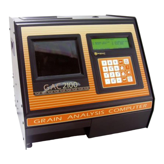
- Page 1 ® S I N C E 1 9 6 6 2100 GRAIN ® ANALYSIS COMPUTER MODELS BLUE, GRAY, AND AGRI...
-
Page 2: Table Of Contents
OPERATOR’S MANUAL Safety Notices ..................... 1 Disclaimer ......................... 1 Introduction ......................3 Accessories ........................3 Features ..........................4 Specifications ........................4 Access Codes ........................5 External Communication Connections ................5 Printer ..........................6 Unpacking the Instrument .................. 7 Disengage Shipping Brace ....................7 Instrument Placement ......................8 Installation ...................... - Page 3 OPERATOR’S MANUAL Instrument Setup ....................39 Clear Cycle Counter (1 Key) ................... 39 ID Options (2 Key) ......................40 Configure Output Options (3 Key) .................. 41 Change The Access Code (4 Key) ................. 44 Change Date, Time and Date Format (5 Key) ..............46 Change Labels (6 Key) ....................
-
Page 4: Safety Notices
DISCLAIMER DICKEY-john reserves the right to make engineering refinements or procedural changes that may not be reflected in this manual. Material included in this manual is for informational purposes and is subject to change without notice. - Page 5 OPERATOR’S MANUAL 2 SAFETY NOTICES GAC® 2100 Grain Analysis Computer (Blue, Gray, Agri Models) 11001-1688-201609...
-
Page 6: Introduction
Null Modem Adapter DB9 Null Modem Adapter 9 pin p/n 220490001 (computer to unit connection) • Communication software package to upload calibrations to unit via a computer (available via email by contacting a DICKEY-john representative). INTRODUCTION 3 GAC® 2100 Grain Analysis Computer (Blue, Gray, Agri Models) -
Page 7: Features
FEATURES GAC 2100 features include: • Memory storage for grain calibrations – 64 grain calibrations (GAC 2100 Blue) – 8 grain calibrations (GAC 2100 AGRI) – 16 grain calibrations (GAC 2100 Gray) • Keyboard entry or computer accessibility for updating grain calibrations as revisions become necessary. -
Page 8: Access Codes
“Changing the Access Code” in “Instrument Setup” section. EXTERNAL COMMUNICATION CONNECTIONS GAC 2100 Blue The GAC 2100 Blue is capable of communicating with a computer via a direct connection using a null modem cable. GAC 2100 AGRI and Gray ®... -
Page 9: Printer
OPERATOR’S MANUAL PRINTER An optional printer connected to the instrument can print test data results. The printout can include: • Facility name and address • Current date and time • Sample ID number • Product name • Grain calibration date •... -
Page 10: Unpacking The Instrument
OPERATOR’S MANUAL UNPACKING THE INSTRUMENT DISENGAGE SHIPPING BRACE The shipping brace must be moved to the operate position before applying power. Since the grain test cell cycles through an unload sequence during power up, damage may occur with the shipping brace in the transport position. -
Page 11: Instrument Placement
OPERATOR’S MANUAL Rotate the brace back into supporting position before moving or shipping the unit. If the cell is not adequately supported operating performance may be adversely affected due to cell bouncing. Some effort is required to move the brace back into position. It may be helpful to reach inside the drawer front and lift up on the cell while attempting to lock the brace into the transport position. - Page 12 OPERATOR’S MANUAL To Level the Instrument: 1. Use the self-contained level on the panel top to position the GAC 2100 on a flat level or nearly level surface. 2. Adjust the four rubber foot pads to level and stabilize the unit (Figure 5).
- Page 13 OPERATOR’S MANUAL 10 UNPACKING THE INSTRUMENT GAC® 2100 Grain Analysis Computer (Blue, Gray, Agri Models) 11001-1688-201609...
-
Page 14: Installation
Save all packing materials until the inspection is complete. If damage is found, immediately file a claim with the carrier and notify your DICKEY-john representative. CONNECTING AC POWER 1. Verify that the ON/OFF (I/O) switch is in the OFF (O) position and that the shipping brace is in the OPERATE position. -
Page 15: Sample Drawer Bypass
OPERATOR’S MANUAL SAMPLE DRAWER BYPASS Normal use of the sample drawer can be bypassed by removing the drawer bottom and cutting a hole into the work counter to allow the tested grain samples to fall through to a larger container below. The size of the hole must be at least equal to the drawer dimension and located directly beneath the grain sample drawer. -
Page 16: Navigation
OPERATOR’S MANUAL NAVIGATION DISPLAY SCREEN The display screen is a graphics Liquid Crystal Display (LCD) and is backlighted for low light level viewing. ADJUST SCREEN CONTRAST The Display Contrast Control is on the rear panel (Figure 6) immediately above the COM1 and COM2 ports. The contrast control changes the contrast between the displayed characters and the background. -
Page 17: Alarm
OPERATOR’S MANUAL ALARM An audible alarm is enabled for 0.5 seconds at the end of each grain analysis or for an error condition. A shorter beep of 0.1 seconds sounds for each valid key stroke. KEY FUNCTIONS BACKSPACE KEY Moves the cursor to the left to delete the last keystroke or to clear an entire entry field. -
Page 18: Menu Screens
OPERATOR’S MANUAL PRINT KEY Initiates a printout of current information on the screen (e.g., grain moisture analysis, calibrations data, etc.). If the automatic printout option is selected, the Print key initiates duplicate copies. Help information does not print. COM SETUP options allows the Print key to transmit to either the printer port or the communications/modem port. -
Page 19: Menu Tree
1: CORN 4: DURUM 2: CORN HI MOIST SETUP MENU 5: FESCUE 3: AMARANTH 4: BARLEY 8: MILLET GAC 2100 Blue 5: DATE/TIME MENU 1: CLEAR COUNTER 6: LABELS MENU 2: ID OPTIONS PAGE 1 OF 8 <MORE> 3: OUTPUT OPTIONS 7: COM MENU <MORE>... -
Page 20: Startup Procedure
OPERATOR’S MANUAL STARTUP PROCEDURE Each time the GAC 2100 is powered on, the instrument performs a series of self checks to determine the status of the following: • Load/strike-off mechanism • Unload function • Empty test cell weight • Conductance/capacitance measurement circuitry Self-checks begin when the hopper doors open, the strike-off arm swings across the cell and back again, and the cell dumps. -
Page 21: Test Samples (Quick Start)
OPERATOR’S MANUAL 2. Select a language by pressing the respective number on the keypad next to the desired language. – This screen only remains available for approximately 8 seconds. – Once selected, an asterisk appears and remains in front of the selection until changed again during another startup cycle. -
Page 22: Measure Moisture
OPERATOR’S MANUAL MEASURE MOISTURE The Main Menu appears immediately after all startup checks have successfully concluded. The Main Menu displays five major selections for categories. To Measure Moisture: 1. Choose MEASURE MOISTURE (1 Key) from the Main menu to display the Select Grain menu. Figure 13 Moisture Testing Preparation MAIN MENU... -
Page 23: Basic Method
3. Press the Load key to begin the test cycle. Enter Key 4. GAC 2100 Blue- If factors (a type of label) are enabled, a screen displays the message ENTER RESULTS FOR THE FOLLOWING. – Disregard this screen by entering a number and selecting the Enter key. - Page 24 OPERATOR’S MANUAL Figure 15 Basic Moisture Measuring Cycle FILL SAMPLE HOPPER, ENTER ID NO. THEN PRESS LOAD TO BEGIN WHEAT HRW 960918 ID:AD1234 Press Load Key MEASURING PLEASE WAIT WHEAT HRW 960918 ID: AD38 13.4% MOISTURE WHEAT HRW 960918 TEMP: 30 C ID: AD38 <more>...
-
Page 25: Grain Sample Id Numbers
OPERATOR’S MANUAL GRAIN SAMPLE ID NUMBERS Three sample ID options may be selected to number grain samples: 1. Automatic number sequencing (e.g., 1, 2, 3...) 2. Manual entry (numbers may be manually entered or skipped) 3. ENTER REQUIRED FOR ID (produces the Enter Sample ID screen) which prompts a required entry before proceeding. -
Page 26: Id Options
Previous Page Key and using the Backspace key to delete letters. – GAC 2100 Blue-Using the S1 through S10 character strings is described in Instrument Setup. Character strings are predetermined phrases to insert into an alpha text line when needed (i.e. -
Page 27: Next Page View
OPERATOR’S MANUAL Figure 17 Example of Factors ENTER RESULTS FOR THE FOLLOWING: CUSTOMER ID VEHICLE NUMBER CODE LOAD WEIGHT 19535 WHEAT HRW 960518 ID: AB1234 NEXT PAGE VIEW After the grain analysis is complete and the moisture content displays, <more> appears on the lower right corner of the screen indicating another page is available. -
Page 28: Grain Selection
SELECT GRAIN MENU Grain Calibration Storage • GAC 2100 Blue-Stores up to 64 unique grain calibrations. The first 40 are restricted and can only be changed by authorized personnel. The remaining 24 are less secure and can be changed using the access code. -
Page 29: Quick Keys
OPERATOR’S MANUAL Figure 19 Select Grain Menus Blue AGRI SELECT GRAIN SELECT GRAIN 1: CORN 5: WHEAT HRW 1: CORN 5: SOYBEANS 2: CORN HI MOIST 6: WHEAT HRS 3: SOYBEANS 7: WHEAT SRW 2: CORN HI MOIST 6: MILO 4. -
Page 30: Calibrate Procedures
OPERATOR’S MANUAL CALIBRATE PROCEDURES The Calibration menu allows authorized personnel to: • view calibration constants of selected grains • enter new or change existing calibrations • print the entire list of stored grain calibrations • obtain calibration data necessary to generate new calibrations •... -
Page 31: Enter/Change Calibration Values (2 Key)
OPERATOR’S MANUAL 6. Press the Next Page key to view the Auto Range screen. The Auto Range screen displays grain name and calibrations automatically used to extend the moisture range if the normal maximum and minimum limits are exceeded. Separate grain calibrations or grains may be referenced for each limit. - Page 32 OPERATOR’S MANUAL To Enter/Change Calibration Values: 1. From the Calibration menu, press the 2 key to access Enter/Change Calibration screen. – (Blue model) PAGE 1 OF 8 of the Select Grain To Enter/Change menu displays. The remaining pages are accessed by selecting the Next Page Key Next Page and Previous Page keys.
- Page 33 OPERATOR’S MANUAL Figure 22 Changing Calibrations CALIBRATION MENU 1: VIEW CALIBRATION 2: ENTER/CHANGE CALIBRATION 3: PRINT CALIBRATION LIST 4: OBTAIN CALIBRATION DATA (Blue model) 5: PRINT AUDIT MEMORY DATA SELECT ITEM NUMBER (NEXT PAGE: STATUS) SELECT GRAIN TO ENTER/CHANGE Page # 1: CORN 5: SOYBEANS varies based...
-
Page 34: Print Calibration Grain List (3 Key)
OPERATOR’S MANUAL 15NOV98) but normally is entered as numbers in a format such as YYMMDD (i.e. 981115). – Pressing the Backspace key will cause the flashing block to disappear allowing the Next Page key to be used for selecting the Enter Key alpha screen. -
Page 35: Obtain Basic Calibration Data (4 Key)
OPERATOR’S MANUAL Figure 23 Printing Calibration Lists CALIBRATION MENU 1: VIEW CALIBRATION 2: ENTER/CHANGE CALIBRATION 3: PRINT CALIBRATION LIST 4: OBTAIN CALIBRATION DATA Blue model 5: PRINT AUDIT MEMORY DATA SELECT ITEM NUMBER (NEXT PAGE: STATUS) PRINT CALIBRATION LIST Press PRINT to LIST CALIBRATIONS OBTAIN BASIC CALIBRATION DATA (4 KEY) This mode allows the user to generate data for developing grain calibrations. - Page 36 OPERATOR’S MANUAL Figure 24 Obtaining Calibration Data CALIBRATION MENU 1: VIEW CALIBRATION 2: ENTER/CHANGE CALIBRATION 3: PRINT CALIBRATION LIST 4: OBTAIN CALIBRATION DATA Blue model 5: PRINT AUDIT MEMORY DATA SELECT ITEM NUMBER (NEXT PAGE: STATUS) PERFORMING SELF CHECKS PLEASE WAIT OBTAIN CALIBRATION DATA ENTER SAMPLE ID OBTAIN CALIBRATION DATA...
-
Page 37: Print Audit Memory Data (5 Key)
OPERATOR’S MANUAL Figure 25 Calibration Data Printout DICKEY-JOHN CORP_GAC 2100 09/29/16 10:32:28 S/N: 1737-90909 CALIBRATION DATA =============== ID: 1.1 STD. MOIST: D3: 2412 D4: 233 =============== PRINT AUDIT MEMORY DATA (5 KEY) (Blue model) The audit memory records data changes made to parameters affecting moisture measurement or the display of the measurement data. - Page 38 OPERATOR’S MANUAL Figure 26 Audit Memory Data DICKEY-JOHN 40554 CURRENT DATE/TIME 29/09/16 10:32:28 S/N: 1716-40554 EVENT COUNTER: DATE OF CHANGE: 09/29/16 MM/DD/YY TIME OF CHANGE: 10.33.25 HH.MM.SS LOG ON TIME: 00.00.00 HH.MM.SS CHGCD: 000000 PID: TIME 10.34.00 HH.MM.SS =============== Figure 27...
-
Page 39: Memory Full
OPERATOR’S MANUAL Each event lists the following items: 1. Date of change 2. Time of change 3. Log on time 4. User code (Figure 26). The user code prints asterisks to maintain user code security. The event (or change) is identified with a PID (Parameter Identification), a colon and then a code to indicate the specific type of change (refer to Table 1). - Page 40 OPERATOR’S MANUAL After Printing Audit Memory: 1. Press the Previous Page key. 2. After printing, select (1 key) to clear audit memory or (2 key) to retain audit memory. Previous Page Key Figure 29 Printing Complete Screen (Blue Model) PRINTING AUDIT MEMORY COMPLETE 1: CLEAR AUDIT MEMORY 2: DO NOT CLEAR AUDIT MEMORY TO PROCEED...
- Page 41 OPERATOR’S MANUAL 38 CALIBRATE PROCEDURES GAC® 2100 Grain Analysis Computer (Blue, Gray, Agri Models) 11001-1688-201609...
-
Page 42: Instrument Setup
OPERATOR’S MANUAL INSTRUMENT SETUP The Setup menu establishes basic operating parameters for the unit. These parameters include: • Resetting the cycle counter • ID options • Output options • Setting the access code • Setting date and time • Entering labels •... -
Page 43: Id Options (2 Key)
OPERATOR’S MANUAL 3. Press the Enter key again to reset the number (count) to zero. The counter returns to zero. Figure 31 NOTE: The date, time, and cycle counter values are Clearing The Cycle Counter automatically sent to the COM1 and COM2 ports each time the counter is cleared resulting in a SETUP MENU... -
Page 44: Configure Output Options (3 Key)
OPERATOR’S MANUAL 3. Select the desired function. Use the Up/Down Arrow keys (0 and 5 keys) to select and the Left/Right Arrow keys (1 and 3 key) to set the desired value. If both selections are set to NO, grain sample ID is &... - Page 45 OPERATOR’S MANUAL Figure 33 Security Button Location Security Button & 5. Verify each option and set as necessary.Three pages must be verified (Figure 34). Use the Up/Down Arrow keys (0 or 5) to select functions Up/Down Arrow Keys and the Left/Right Arrow keys (1 or 3) to set each function to the appropriate setting.
- Page 46 OPERATOR’S MANUAL do not display if either weight and/or moisture is out-of-limits. 6. MW- Enabled readings display if moisture and/or weight is out-of-limits but do not display if temperature is out of limits. This is the current approved setting for NTEP units. 7.
-
Page 47: Change The Access Code (4 Key)
OPERATOR’S MANUAL Figure 34 Setting Output Options SETUP MENU 5: DATE/TIME MENU 1: CLEAR COUNTER 2: ID OPTIONS 6: LABELS MENU 7: COM MENU 3: OUTPUT OPTIONS 4: EDIT ACCESS CODE 8: SERVICE MENU SELECT ITEM NUMBER <more> OUTPUT OPTIONS TO PROCEED UNSEAL ACCESS PORT ON REAR PANEL AND DEPRESS WHITE PUSHBUTTON... - Page 48 The access code is set to 0 when shipped from the factory. After selecting a different code, record the new number and store for safe keeping. DO NOT lose the new code. Contact DICKEY-john or your local authorized service center to recover the access code.
-
Page 49: Change Date, Time And Date Format (5 Key)
OPERATOR’S MANUAL CHANGE DATE, TIME, AND DATE FORMAT (5 KEY) This function establishes correct date and time for display and print out with Enter Key each grain moisture measurement. To Set the Time: 1. From the Setup menu, select the Date/Time menu (5 key). Three options are available;... - Page 50 OPERATOR’S MANUAL To Change the Date: 1. From the Date/Time menu, select the SET DATE (2 key) menu (Figure 37). The Set Date screen displays ENTER ACCESS CODE. 2. Enter the access code to gain and select the Enter key. Enter numbers in the format shown at display bottom: month.day.year.
-
Page 51: Change Labels (6 Key)
OPERATOR’S MANUAL Figure 38 Setting Date Format DATE/TIME MENU 1: SET TIME 2: SET DATE 3: SET DATE FORMAT SELECT ITEM NUMBER (NEXT PAGE: STATUS) SET DATE FORMAT ENTER ACCESS CODE: __ SET DATE FORMAT DATE FORMAT: MM/DD/YY to CHANGE CHANGE LABELS (6 KEY) The Labels menu edits three label types: –... - Page 52 SELECT ITEM NUMBER (NEXT PAGE: STATUS) EDIT USER NAME ENTER ACCESS CODE: __ EDIT USER NAME LINE 1: DICKEY-JOHN LINE 2: GAC2100 Press to EDIT To Create Labels: 1. From the Setup menu, select the Labels menu (6 key). The Labels menu offers choices: –...
- Page 53 OPERATOR’S MANUAL four factors can be assigned to each grain. After selecting a grain, the EDIT FACTOR NAMES will appear for entry. – To delete existing factor names from the grain calibration, begin by selecting the grain and the factor name to be deleted. –...
-
Page 54: Set Communications Port Parameters (7 Key)
OPERATOR’S MANUAL Figure 41 Edit Factor Names (Blue Model) LABELS MENU 1: EDIT USER NAME 2: EDIT TEXT STRINGS 3: EDIT FACTOR NAMES SELECT ITEM NUMBER (NEXT PAGE: STATUS) EDIT FACTOR NAMES ENTER ACCESS CODE: __ SELECT GRAIN TO ENTER/CHANGE 1: CORN 5: SOYBEANS 2: CORN HI MOIST... - Page 55 OPERATOR’S MANUAL To Configure the Communications Ports (Basic entry procedure – Followup to specific subject for finishing details): 1. From the Main menu, select the 4 key (Setup menu) and then the 7 key (COM menu). – The Communications menu appears with seven active choices and one non-active selection.
- Page 56 OPERATOR’S MANUAL The four outputs are defined as follows (Figure 43): – AUTOMATIC RESULTS OUTPUT - The configured port produces an output to automatically print the moisture results. – MANUAL RESULTS OUTPUT - Produces a printout for the configured port of the results by selecting the Print key. Repeatedly selecting the Print key results in duplicate copies.
- Page 57 OPERATOR’S MANUAL To Configure COM1 or COM2 Format: (2 or 6 key from the Communications menu): 1. After completing steps 1 through 4 from the basic entry procedure, edit the configuration. Both the COM1 FORMAT and COM2 FORMAT selections are similar and therefore are described together. The COM Format Selection menu displays two lines each containing several choices (Figure...
- Page 58 OPERATOR’S MANUAL Figure 44 Setting Output Format SETUP MENU 1: CLEAR COUNTER 5: DATE/TIME MENU 6: LABELS MENU 2: ID OPTIONS 7: COM MENU 3: OUTPUT OPTIONS 8: SERVICE MENU 4: EDIT ACCESS CODE SELECT ITEM NUMBER <more> COMMUNICATIONS MENU 5: non-active 1: COM PORT SELECT 6: COM2 FORMAT...
- Page 59 OPERATOR’S MANUAL 3. Select the DATA BITS, PARITY and STOP BITS in that order. The items for the COM1 and COM2 port cannot be changed: – DATA BITS – Set for 8-bit character lengths. – PARITY – Set to NONE by using the Left/Right Arrow keys. –...
- Page 60 OPERATOR’S MANUAL control lead busy sense has three polarity choices: IGNORE, ACTIVE (+), or ACTIVE (-). The DTR (20) (data terminal ready) line notifies the GAC 2100 that the printer (computer) is turned ON. The Control Lead DTR Sense has two states: IGNORE or ACTIVE.
-
Page 61: Non-Active (5 Key From Communications Menu)
No other action results. SERVICE MENU (8 KEY) The Service menu contains individual unit calibration constants and is accessed by DICKEY-john trained and equipped service personnel. QUICK KEYS MENU Blue Model- QUICK KEYS makes changing between frequently-used grains easier during moisture measurements by bypassing the Select Grain menu. -
Page 62: Test Weight Bias Adjustment
OPERATOR’S MANUAL Figure 48 Programming The Quick Keys SETUP MENU 5: DATE/TIME MENU 1: CLEAR COUNTER 6: LABELS MENU 2: ID OPTIONS 3: OUTPUT OPTIONS 7: COM MENU 4: EDIT ACCESS CODE 8: SERVICE MENU SELECT ITEM NUMBER <more> SETUP MENU 1: QUICK KEYS MENU 2: TEST WEIGHT BIAS ADJUSTMENT 3: TEST WEIGHT SLOPE ADJUSTMENT... - Page 63 OPERATOR’S MANUAL stroke. Advance until the correct grain displays. If the end of the list is reached, the list wraps to the beginning and starts again. & 5. When the correct grain is found, press the Enter key. The final screen appears for editing the TEST WEIGHT BIAS OFFSET value.
-
Page 64: Test Weight Slope Adjustment
OPERATOR’S MANUAL TEST WEIGHT SLOPE ADJUSTMENT Test weight slope adjustment allows entering a slope correction factor for differences between the GAC 2100 grain test weight slope and the official test weight slope reference. A slope value should only be changed by an authorized user. -
Page 65: Moisture Bias Adjustment
OPERATOR’S MANUAL Figure 50 Test Weight Slope Adjustment SETUP MENU 5: DATE/TIME MENU 1: CLEAR COUNTER 2: ID OPTIONS 6: LABELS MENU 3: OUTPUT OPTIONS 7: COM MENU 4: EDIT ACCESS CODE 8: SERVICE MENU SELECT ITEM NUMBER <more> Blue SETUP MENU model 1: QUICK KEYS MENU... - Page 66 OPERATOR’S MANUAL Locating the Instrument Security Button: 3. Locate the access port door located on the back of the instrument and remove seal, if necessary, from the door. 4. Remove screw to open access port door. 5. Press the white security button to advance to the next Moisture Bias Adjustment screen.
-
Page 67: Moisture Slope Adjustment
OPERATOR’S MANUAL Figure 52 Moisture Bias Adjustment SETUP MENU 1: CLEAR COUNTER 5: DATE/TIME MENU 2: ID OPTIONS 6: LABELS MENU 7: COM MENU 3: OUTPUT OPTIONS 8: SERVICE MENU 4: EDIT ACCESS CODE SELECT ITEM NUMBER <more> SETUP MENU Blue model 1: QUICK KEYS MENU 2: TEST WEIGHT BIAS ADJUSTMENT... - Page 68 OPERATOR’S MANUAL 4. Remove screw to open access port door. 5. Press the white security button to advance to the next Slope Bias Adjustment screen. 6. At the display screen, use the Left/Right Arrow keys to select the grain & type for correction.
- Page 69 OPERATOR’S MANUAL 66 INSTRUMENT SETUP GAC® 2100 Grain Analysis Computer (Blue, Gray, Agri Models) 11001-1688-201609...
-
Page 70: Test Unit Performance
OPERATOR’S MANUAL TEST UNIT PERFORMANCE The Tests menu displays diagnostic tests and status information for operating values. The information is useful to technicians in evaluating overall performance and isolating problems. During normal operation, these are not generally referenced. However, problem identification can be assisted by reviewing certain values occasionally and observing changes. -
Page 71: View Com2 Transmit Port (3 Key)
OPERATOR’S MANUAL 2. Verify that a printer is connected and select the Print key to print a sample of the entire TRANSMIT CHARACTER SET. When completed, select the Previous Page key to return to the Tests menu. Figure 55 Previous Page Key Entering The COM1 Test Menu TESTS MENU 1: non-active... -
Page 72: View Display Characters (5 Key)
OPERATOR’S MANUAL VIEW DISPLAY CHARACTERS (5 KEY) The display screen indicates typical characters the instrument is capable of producing for operator-generated messages (Figure 57). To Access Characters: 1. From the Test menu, select the 5 key to choose DISPLAY. The screen shows characters, symbols, and digits that can display by the unit. -
Page 73: View Diagnostic Mode (6 Key)
OPERATOR’S MANUAL VIEW DIAGNOSTIC MODE (6 KEY) The Diagnostic Mode accesses unit operating values. Most of the readout values relate to the test cell circuitry. To Access Diagnostic Details: 1. Press the 6 key to enter DIAGNOSTIC MODE (PAGE 1). Two pages of information are available (Figure 58). - Page 74 OPERATOR’S MANUAL 3. Press the Next Page key to view PAGE 2 of the DIAGNOSTIC MODE. The display screen is divided into two columns: 5 kHz and 2 MHz (Figure 58). – 5 kHz (D1) – Left half of screen Next Page key 1: Vc - Voltage of 5 kHz oscillator.
-
Page 75: Test Network Mode (7 Key)
OPERATOR’S MANUAL TEST NETWORK MODE (7 KEY) This mode is used by trained, authorized personnel in troubleshooting. The screens and printout are shown for reference only. To Access the TEST NETWORK: 1. Press the 7 key - TEST NETWORK MODE (Figure 61). -
Page 76: View/Print Parameters (8 Key)
OPERATOR’S MANUAL Figure 62 Test Mode Printout DICKEY-JOHN, CORP. GAC2100 05/18/13 09:18:59 D1CF: 15000 D1CE: 15000 14,4 D2CF: 14853 D2CE: 14853 204,3 D4TF: 20,43 D4TE: 20,39 SELECT TEST NUMBER VIEW/PRINT PARAMETERS (8 KEY) The Parameters menu (8 key) operates similarly to the Service menu located under the Setup menu. - Page 77 OPERATOR’S MANUAL Figure 63 Viewing Parameters Menu TESTS MENU 1: non-active 5: DISPLAY 6: DIAGNOSTIC MODE 2: COM1 3: COM2 TRANSMIT 7: TEST NETWORK MODE 4: non-active 8: PARAMETERS MENU SELECT ITEM NUMBER (NEXT PAGE: STATUS) PARAMETERS MENU 1: VIEW TEMPERATURE CONSTANTS 2: VIEW EMPTY CELL WEIGHT COUNTS 3: VIEW WEIGHT CONSTANTS #4.
- Page 78 OPERATOR’S MANUAL Figure 64 Parameters Value Printout 05/18/16 09:59:59 S/N: 1716-23601 REF TEMP: 25,00 REF VOLT: 1,1560 EC COUNT: 40399 WEIGHT TABLE: 0,000 1,00000 61,500 1,02754 3 120,400 1,05453 4 181,800 1,08340 5 240,600 1,11179 6 300,300 1,14108 CAC: 1,0000 1122 BURN IN MODE: ERROR STORING:...
- Page 79 OPERATOR’S MANUAL 76 TEST UNIT PERFORMANCE GAC® 2100 Grain Analysis Computer (Blue, Gray, Agri Models) 11001-1688-201609...
-
Page 80: Operator Maintenance
OPERATOR’S MANUAL OPERATOR MAINTENANCE CELL CLEANING - DAILY 1. From the Main menu, select the 5-key to display the Tests menu. Then select the 6-key to display the Diagnostics menu. Load Key 2. When the Diagnostics menu displays select the Load key. The hopper doors open and remain open until the Unload key is selected. -
Page 81: Error Codes
DICKEY-john representative. An onboard RAM memory error has occurred. Turn the power OFF for at least 5 seconds; turn power system ON. If the condition continues, contact a DICKEY-john representative for assistance. NOT USED The real-time clock battery is faulty. -
Page 82: Appendix A: Communication Ports
OPERATOR’S MANUAL APPENDIX A: COMMUNICATION PORTS COM1 PORT OPTIONS The COM1 Port (refer to Table 2) is a serial port conforming to the EIA/TIA NOTE: COM 1 port requires a standard DTE/DCE RS 232 cable without RS-232-E standard and configured as Data Communication Equipment a null modem when connecting (DCE). -
Page 83: Com2 Pin Assignment Details
OPERATOR’S MANUAL Data Terminal Ready (pin 20) – Indicates the connected device is not available. The COM1 Control Lead Setup screen configures this line as ACTIVE or IGNORE. If configured ACTIVE, an OFF condition (negative or zero voltage) inhibits the transmission of data from the GAC 2100. - Page 84 OPERATOR’S MANUAL Request To Send (pin 4) – Configured ON (positive voltage) whenever unit is powered or to be ON (positive voltage) only when there is data in the COM2 buffer to be transmitted. Use the COM2 Control Lead Setup screen to configure this line.
- Page 85 OPERATOR’S MANUAL 82 APPENDIX A: COMMUNICATION PORTS GAC® 2100 Grain Analysis Computer (Blue, Gray, Agri Models) 11001-1688-201609...
-
Page 86: Warranty
Europe: DICKEY-john Europe S.A.S, 165, boulevard de Valmy, 92706 – Colombes – France TEL: 33 (0) 1 41 19 21 80, FAX: 33 (0) 1 47 86 00 07 WEB: www.dickey-john.com Copyright 2016 DICKEY-john Specifications subject to change without notice. - Page 87 DICKEY-john Technical Support 800-637-3302 service@dickey-john.com Europe Sales and Technical Support +33 1 41 19 21 80 europe@dickey-john.com DICKEY-john, the DICKEY-john Logo and GAC are 5200 Dickey-john Road 217-438-3371 ® registered trademarks of DICKEY-john Corporation. Auburn, IL 62615 217-438-6012 fax S I N C E 1 9 6 6 www.dickey-john.com...
Need help?
Do you have a question about the gac 2100 blue and is the answer not in the manual?
Questions and answers