Table of Contents
Advertisement
OPERATOR'S MANUAL
Safety Notices ..................................................................................................... 1
Disclaimer ......................................................................................................................... 1
Introduction ......................................................................................................... 3
Accessories ....................................................................................................................... 3
Features ............................................................................................................................ 4
Specifications .................................................................................................................... 4
External Communication Connections .............................................................................. 4
Printer ............................................................................................................................... 5
Unpacking the Instrument .................................................................................. 7
Disengage Shipping Brace ............................................................................................... 7
Instrument Placement ....................................................................................................... 8
Installation ......................................................................................................... 11
Connecting AC Power ..................................................................................................... 11
Navigation .......................................................................................................... 13
Display Screen ................................................................................................................ 13
Adjust Screen Contrast ................................................................................................... 13
Keyboard Layout ............................................................................................................. 13
Alarm ............................................................................................................................... 14
Key Functions ................................................................................................................. 14
Menu Screens ................................................................................................................. 15
Analyzing Grain ................................................................................................. 17
Startup Procedure ........................................................................................................... 17
Quick Start Grain Analysis .............................................................................................. 17
Prepare To Test Moisture ............................................................................................... 18
Grain Analysis (Standard Method) .................................................................................. 19
Grain Sample ID Numbers .............................................................................................. 21
Enter Numbers And Alpha Characters ............................................................................ 21
ID Options ....................................................................................................................... 22
Next Page View .............................................................................................................. 22
Grain Selection .................................................................................................. 23
Select Grain Menu .......................................................................................................... 23
Calibrate Procedures ...................................................................................................... 24
View Calibration Data (1 Key) ......................................................................................... 24
Enter/Change Calibration Values (2 Key) ....................................................................... 25
Print Calibration Grain List (3 Key) ................................................................................. 27
Obtain Basic Calibration Data (4 Key) ............................................................................ 28
GAC2100 AGRI (US)
11001-1656-201505
/ I
Advertisement
Table of Contents

Related Manuals for Dickey-John GAC 2100 AGRI


Summary of Contents for Dickey-John GAC 2100 AGRI
-
Page 1: Table Of Contents
OPERATOR’S MANUAL Safety Notices ..................... 1 Disclaimer ......................... 1 Introduction ......................3 Accessories ........................3 Features ..........................4 Specifications ........................4 External Communication Connections ................4 Printer ..........................5 Unpacking the Instrument .................. 7 Disengage Shipping Brace ....................7 Instrument Placement ....................... 8 Installation ...................... - Page 2 OPERATOR’S MANUAL Establish Parameters ..................31 Clear The Cycle Counter (1 Key) ................... 31 Choose ID Options (2 Key) ..................... 32 Configure Output Options (3 Key) .................. 33 Change Access Code (4 Key) ..................37 Change Date, Time, And Date Format (5 Key) .............. 38 Change Labels (6 Keys) ....................
-
Page 3: Safety Notices
DISCLAIMER DICKEY-john reserves the right to make engineering refinements or procedural changes that may not be reflected in this manual. Material included in this manual is for informational purposes and is subject to change without notice. - Page 4 OPERATOR’S MANUAL 2 SAFETY NOTICES GAC2100 AGRI (US) 11001-1656-201505...
-
Page 5: Introduction
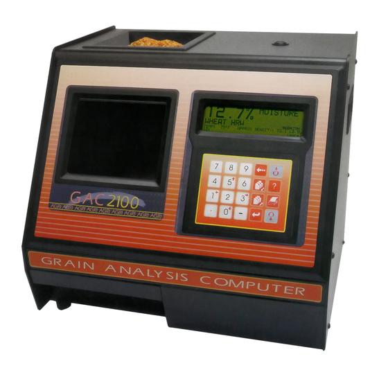
OPERATOR’S MANUAL INTRODUCTION ® The DICKEY-john Grain Analysis Computer GAC 2100 AGRI quickly tests grain samples for moisture content and other profile information. The unit loads a sample, weighs and checks temperature, runs the test, displays the results, and unloads the sample. -
Page 6: Features
Weight: 11.8 kg (26 lbs) - Shipping Weight: 15.0 kg (33 lbs) EXTERNAL COMMUNICATION CONNECTIONS The GAC 2100 AGRI can output to a personal computer (PC) using the COM1 or COM2 ports. The two communication ports are located on the rear of the unit and are identified as Printer Output Port (COM1) and Computer Output Port (COM2). -
Page 7: Printer
OPERATOR’S MANUAL Figure 2 Communication Ports COM1 Port COM2 Port Access Port PRINTER An optional printer connected to the instrument can print test data results. The printout can include: • Facility name and address • Current date and time • Sample ID number •... - Page 8 OPERATOR’S MANUAL 6 INTRODUCTION GAC2100 AGRI (US) 11001-1656-201505...
-
Page 9: Unpacking The Instrument
The GAC 2100 AGRI is shipped with the grain test cell supported by an internal shipping/transport brace. This brace is to support the test cell whenever the unit is transported. -
Page 10: Instrument Placement
INSTRUMENT PLACEMENT Choose a clean environment for the GAC 2100 AGRI that is protected from rapid changes in ambient temperature. Avoid a hazardous (classified) location as defined in Article 500 of the NFPA Handbook of the National Electrical Code. - Page 11 OPERATOR’S MANUAL To Level the Instrument: 1. Use the self-contained level on the panel top to position the GAC 2100 AGRI on a flat level or nearly level surface. 2. Adjust the four rubber foot pads to level and stabilize the unit. To adjust the foot pad height, unlock the upper nut from the bottom panel of the selected foot pad.
- Page 12 OPERATOR’S MANUAL 10 UNPACKING THE INSTRUMENT GAC2100 AGRI (US) 11001-1656-201505...
-
Page 13: Installation
OPERATOR’S MANUAL INSTALLATION Before shipping, the GAC 2100 AGRI is inspected and tested for mechanical and electrical defects. After unpacking, visually inspect for damage occurring during transit. Save all packing materials until the inspection is complete. If damage is found, immediately file a claim with the carrier and notify your DICKEY-john Sales Representative. - Page 14 OPERATOR’S MANUAL SAMPLE DRAWER BYPASS Normal use of the sample drawer can be bypassed by removing the drawer bottom and cutting a hole into the work counter to allow the tested grain samples to fall through to a larger container below. The size of the hole must be at least equal to the drawer dimension and located directly beneath the grain sample drawer.
-
Page 15: Navigation
OPERATOR’S MANUAL NAVIGATION DISPLAY SCREEN The display screen is a graphics Liquid Crystal Display (LCD) and is backlit for low light level viewing. ADJUST SCREEN CONTRAST The Display Contrast Control is on the rear panel immediately above the COM1 and COM2 ports (Figure 6). -
Page 16: Alarm
OPERATOR’S MANUAL ALARM An audible alarm is enabled for 0.5 seconds at the end of each grain analysis or for an error condition. A shorter beep of 0.1 seconds sounds for each valid key stroke. KEY FUNCTIONS BACKSPACE KEY Moves the cursor to the left to delete the last keystroke or to clear an entire entry field. -
Page 17: Menu Screens
OPERATOR’S MANUAL PRINT KEY Initiates a printout of current information on the screen (e.g., grain moisture analysis, calibrations data, etc.). If the automatic printout option is selected, the Print key initiates duplicate copies. Help information does not print. COM SETUP options allow the Print key to transmit to either the printer port or the communications/modem port. - Page 18 OPERATOR’S MANUAL Figure 11 Menu Tree MAIN MENU 1: MEASURE MOISTURE 2: SELECT GRAIN 4: SETUP MENU 3: CALIBRATION MENU 5: TESTS MENU (NEXT PAGE: STATUS) SELECT ITEM NUMBER SETUP MENU FILL SAMPLE HOPPER, ENTER ID NO. THEN 5: DATE/TIME MENU 1: CLEAR COUNTER 6: LABELS MENU PRESS LOAD TO BEGIN...
-
Page 19: Analyzing Grain
OPERATOR’S MANUAL ANALYZING GRAIN STARTUP PROCEDURE Each time the GAC 2100 AGRI is powered, the instrument performs a series of self checks to determine the status of the following: • Load/strike off mechanism • Unload function • Empty test cell weight •... -
Page 20: Prepare To Test Moisture
OPERATOR’S MANUAL PREPARE TO TEST MOISTURE The Main Menu appears immediately after all startup checks have successfully concluded. The Main Menu displays five major selections for Down Arrow key categories. To measure moisture: 1. Choose MEASURE MOISTURE (1 Key) from the Main window to display the Select Grain menu. -
Page 21: Grain Analysis (Standard Method)
OPERATOR’S MANUAL Figure 13 Screen Sequence Using Enter Required For ID ENTER SAMPLE ID 960918 WHEAT HRW FILL SAMPLE HOPPER AND PRESS LOAD TO BEGIN WHEAT HRW 960918 ID:AD38 GRAIN ANALYSIS (STANDARD METHOD) After all calibration self-checks for the selected grain are complete (approximately 10 seconds), the message FILL SAMPLE HOPPER, ENTER ID NO. - Page 22 OPERATOR’S MANUAL Figure 14 Basic Moisture Measuring Cycle FILL SAMPLE HOPPER, ENTER ID NO. THEN PRESS LOAD TO BEGIN WHEAT HRW 960918 ID:AD1234 Select Load Key MEASURING PLEASE WAIT 960918 WHEAT HRW ID: AD38 13.4% MOISTURE WHEAT HRW 960918 TEMP: 30 C ID: AD38 <more>...
-
Page 23: Grain Sample Id Numbers
OPERATOR’S MANUAL GRAIN SAMPLE ID NUMBERS Three sample ID options may be selected to number grain samples; 1. Automatic number sequencing (e.g., 1, 2, 3...) 2. Manual entry (numbers may be manually entered or skipped) 3. ENTER REQUIRED FOR ID (produces the Enter Sample ID screen) which prompts a required entry before proceeding. -
Page 24: Id Options
OPERATOR’S MANUAL 5. After completing the text string, press the Previous Page key. The text string will become part of the ID field on the Press Load To Begin screen. Additional numbers may be inserted after the text string as before. -
Page 25: Grain Selection
Select Grain menu must be selected manually. SELECT GRAIN MENU The GAC 2100 AGRI stores up to 8 different grain calibrations. To Select a Grain for Testing: 1. Choose the Select Grain menu from the Main menu by pressing the 2 key. -
Page 26: Calibrate Procedures
OPERATOR’S MANUAL CALIBRATE PROCEDURES The Calibration menu allows authorized personnel to: • view the calibration constants of selected grains • enter new or change existing calibrations • print the entire list of stored grain calibrations • obtain calibration data necessary to generate new calibrations Choose a function by selecting the number key corresponding to the desired function. -
Page 27: Enter/Change Calibration Values (2 Key)
OPERATOR’S MANUAL Figure 19 View Calibration Menu Showing Wheat HRW CALIBRATION MENU 1: VIEW CALIBRATION 2: ENTER/CHANGE CALIBRATION 3: PRINT CALIBRATION LIST 4: OBTAIN CALIBRATION DATA SELECT ITEM NUMBER (NEXT PAGE: STATUS) SELECT GRAIN 1: CORN 5: WHEAT HRW 2: CORN HI MOIST 6: WHEAT HRS 3: SOYBEANS 7: WHEAT SRW... - Page 28 OPERATOR’S MANUAL Figure 20 Changing Calibrations CALIBRATION MENU 1: VIEW CALIBRATION 2: ENTER/CHANGE CALIBRATION 3: PRINT CALIBRATION LIST 4: OBTAIN CALIBRATION DATA SELECT ITEM NUMBER (NEXT PAGE: STATUS) SELECT GRAIN 1: CORN 5: WHEAT HRW 2: CORN HI MOIST 6: WHEAT HRS 3: SOYBEANS 7: WHEAT SRW 4: SORGHUM...
-
Page 29: Print Calibration Grain List (3 Key)
OPERATOR’S MANUAL 11. When finished, press the Enter key to accept the constant and to advance to the next position. If the screen is accidentally advances before finishing, press the Enter key as many times as necessary to cycle through all menu items. Enter key 12. -
Page 30: Obtain Basic Calibration Data (4 Key)
Enter key thirty minutes to warm up before taking sample readings. 2. Turn the printer ON. Be certain the GAC 2100 AGRI is set up and functioning properly. 3. From the Main menu, choose the Calibration menu by pressing the 3 key. - Page 31 PLEASE WAIT OBTAIN CALIBRATION DATA ID: 22 D3: 2467 OBTAIN CALIBRATION DATA DATE: 09/15/13 TIME: 20:10:19 ID: 22 Figure 23 Calibration Data Printout DICKEY-JOHN 10653 04/21/13 06:42:33 S/N: 1640-10653 CALIBRATION DATA ================== STD. MOIST: ================== GRAIN SELECTION 29 GAC2100 AGRI (US)
- Page 32 OPERATOR’S MANUAL 30 GRAIN SELECTION GAC2100 AGRI (US) 11001-1656-201505...
-
Page 33: Establish Parameters
OPERATOR’S MANUAL ESTABLISH PARAMETERS The Setup menu establishes basic operating parameters for the unit. These parameters include resetting the cycle counter, ID options, output options, setting the access code, setting date and time, entering labels, and configuring communication ports. From the Main menu, the Setup menu is accessed by selecting the 4 key. From the Setup menu, eight sub-menus will appear. -
Page 34: Choose Id Options (2 Key)
OPERATOR’S MANUAL Figure 25 Clearing The Cycle Counter SETUP MENU 1: CLEAR COUNTER 5: DATE/TIME MENU 6: LABELS MENU 2: ID OPTIONS 3: OUTPUT OPTIONS 7: COM MENU 4: EDIT ACCESS CODE 8: SERVICE MENU SELECT ITEM NUMBER (NEXT PAGE: STATUS) CYCLE COUNTERS ENTER ACCESS CODE: __ CYCLE COUNTER:... -
Page 35: Configure Output Options (3 Key)
OPERATOR’S MANUAL Figure 26 Selecting ID Options SETUP MENU 1: CLEAR COUNTER 5: DATE/TIME MENU 2: ID OPTIONS 6: LABELS MENU 3: OUTPUT OPTIONS 7: COM MENU 4: EDIT ACCESS CODE 8: SERVICE MENU (NEXT PAGE: STATUS) SELECT ITEM NUMBER ID OPTIONS ENTER ACCESS CODE: __ ID OPTIONS... - Page 36 OPERATOR’S MANUAL Figure 27 Security Button Location Security Button 5. Verify each option and set as necessary. Three pages must be verified (Figure 29). Use the Up/Down Arrow keys (0 or 5 keys) to select & functions and the Left/Right Arrow keys (1 or 3 keys) to set each function to the appropriate setting.
- Page 37 OPERATOR’S MANUAL 8. WT - enabled readings display if weight and/or temperature is out-of-limits but does not display if moisture is out of limits. – Output Out-of-Limits Result: if enabled, three standard parameters are printed - moisture, grain temperature, and approximate grain test weight.
- Page 38 OPERATOR’S MANUAL Figure 28 Setting Output Options SETUP MENU 1: CLEAR COUNTER 5: DATE/TIME MENU 2: ID OPTIONS 6: LABELS MENU 3: OUTPUT OPTIONS 7: COM MENU 8: SERVICE MENU 4: EDIT ACCESS CODE SELECT ITEM NUMBER (NEXT PAGE: STATUS) OUTPUT OPTIONS TO PROCEED UNSEAL ACCESS PORT ON REAR PANEL...
-
Page 39: Change Access Code (4 Key)
OPERATOR’S MANUAL CHANGE ACCESS CODE (4 KEY) The access code establishes a security level for nearly all Setup menu functions. To change the access code: NOTE: The access code is set to 0 when shipped from the factory. 1. From the Setup menu, select the EDIT ACCESS CODE (4 key). The After selecting a different code, screen displays ENTER ACCESS CODE. -
Page 40: Change Date, Time, And Date Format (5 Key)
OPERATOR’S MANUAL CHANGE DATE, TIME, AND DATE FORMAT (5 KEY) This function establishes correct date and time for display and print out with each grain moisture measurement. To set the time: 1. From the Setup menu, select the Date/Time menu (5 key). Three options are available: 1) Set Time, 2) Set Date, and 3) Set Date Format. - Page 41 OPERATOR’S MANUAL To change the date: 1. From the Date/Time menu, select SET DATE using the 2 key. The Set Date screen will display ENTER ACCESS CODE. 2. Enter the access code to gain access and select the Enter key. Enter numbers in the format shown at the bottom of the display: month.day.year.
-
Page 42: Change Labels (6 Keys)
OPERATOR’S MANUAL Figure 32 Setting Date Format DATE/TIME MENU 1: SET TIME 2: SET DATE 3: SET DATE FORMAT SELECT ITEM NUMBER (NEXT PAGE: STATUS) SET DATE FORMAT ENTER ACCESS CODE: __ SET DATE FORMAT DATE FORMAT: MM/DD/YY to CHANGE CHANGE LABELS (6 KEYS) The Labels menu allows editing user name and attaches to the grain moisture measurements. -
Page 43: Set Communication Port Parameters (7 Key)
(NEXT PAGE: STATUS) SELECT ITEM NUMBER LABELS MENU 1: EDIT USER NAME EDIT USER NAME ENTER ACCESS CODE: __ EDIT USER NAME LINE 1: DICKEY-JOHN LINE 2: GAC2100 Press to EDIT SET COMMUNICATION PORT PARAMETERS (7 KEY) Selection of the COM (Communications) menu is established through the Setup menu by selecting the 7 key. - Page 44 OPERATOR’S MANUAL 4. Proceed with the necessary editing of the selection. Selections include: – COM port select – COM1 or COM2 format – COM1 or COM2 serial data setup – COM1 or COM2 control lead setup Figure 34 Accessing The COM Menu SETUP MENU 1: CLEAR COUNTER 5: DATE/TIME MENU...
- Page 45 OPERATOR’S MANUAL Figure 35 Accessing COM Port Select SETUP MENU 5: DATE/TIME MENU 1: CLEAR COUNTER 2: ID OPTIONS 6: LABELS MENU 3: OUTPUT OPTIONS 7: COM MENU 4: EDIT ACCESS CODE 8: SERVICE MENU SELECT ITEM NUMBER (NEXT PAGE: STATUS) COMMUNICATIONS MENU 5: non-active 1: COM PORT SELECT...
- Page 46 OPERATOR’S MANUAL 4. Select the LINE TERMINATOR with the pointer. An RS-232 line of input data must be terminated with one of the following characters or character pairs. – LF (line feed) 0A Hex – CR (carriage return) 0D Hex –...
- Page 47 OPERATOR’S MANUAL 2. Select the DATA BITS, PARITY, and STOP BITS in that order. These items for the COM1 port cannot be changed. The COM2 port items may be adjusted. Definitions of each item are as follows: – Data Bits - set for 7- or 8-bit character lengths –...
- Page 48 OPERATOR’S MANUAL The busy line, BUSY (11) notifies the GAC 2100 AGRI when the buffer in the printer (computer) is full and cannot accept more data. The polarity of this line is important and is set to be compatible with the printer.
- Page 49 OPERATOR’S MANUAL Figure 38 Accessing COM Control Lead Setup Screen SETUP MENU 5: DATE/TIME MENU 1: CLEAR COUNTER 6: LABELS MENU 2: ID OPTIONS 3: OUTPUT OPTIONS 7: COM MENU 4: EDIT ACCESS CODE 8: SERVICE MENU SELECT ITEM NUMBER (NEXT PAGE: STATUS) COMMUNICATIONS MENU 5: non-active...
-
Page 50: Non Active (5 Key From Communications Menu)
TEST WEIGHT BIAS ADJUSTMENT Test weight bias adjustment allows entering a correction factor for differences between the GAC 2100 AGRI grain test weight and the official test weight reference. IMPORTANT: A bias value should only be changed by an authorized user. -
Page 51: Test Weight Slope Adjustment
TEST WEIGHT SLOPE ADJUSTMENT Test weight slope adjustment allows entering a slope correction factor for differences between the GAC 2100 AGRI grain test weight slope and the official test weight slope reference. A slope value should only be changed by an authorized user. - Page 52 OPERATOR’S MANUAL 7. Press the Left/Right Arrow keys to select the desired digit to change. 8. Change the selected value with the Up/Down Arrow keys. The value of the number changes on the TEST WEIGHT SLOPE line with each & button press.
-
Page 53: Moisture Bias Adjustment
OPERATOR’S MANUAL MOISTURE BIAS ADJUSTMENT Moisture bias adjustment allows entry of a correction factor for differences between the GAC 2100 AGRI grain moisture and the official moisture reference. IMPORTANT: Pressing the security switch located internally on the circuit board is required to gain access to Moisture Bias and Moisture Slope Adjustment screens. - Page 54 OPERATOR’S MANUAL 8. Press the Left/Right Arrow keys to select the desired digit to change. 9. Change the selected value with the Up/Down Arrow keys. The value & of the number changes on the MOISTURE BIAS line with each button press.
-
Page 55: Slope Bias Adjustment
OPERATOR’S MANUAL MOISTURE SLOPE ADJUSTMENT Moisture Slope adjustment allows entry of a slope correction factor for differences between the GAC 2100 AGRI grain moisture and the official moisture reference. A bias value should only be changed by an authorized user. - Page 56 OPERATOR’S MANUAL Figure 44 Moisture Slope Adjustment SETUP MENU 1: CLEAR COUNTER 5: DATE/TIME MENU 2: ID OPTIONS 6: LABELS MENU 7: COM MENU 3: OUTPUT OPTIONS 8: SERVICE MENU 4: EDIT ACCESS CODE <more> SELECT ITEM NUMBER SETUP MENU 1: TEST WEIGHT BIAS ADJUSTMENT 2: TEST WEIGHT SLOPE ADJUSTMENT 3: MOISTURE BIAS ADJUSTMENT...
-
Page 57: Testing Unit Performance
OPERATOR’S MANUAL TESTING UNIT PERFORMANCE The Tests menu displays diagnostic tests and status information for operating values. The information is useful to technicians in evaluating overall performance and isolating problems. During normal operation, these are not generally referenced. However, problem identification can be assisted by reviewing certain values occasionally and observing changes. -
Page 58: View Com2 Transmit Port (3 Key)
OPERATOR’S MANUAL Figure 46 Entering The COM1 Test Menu TESTS MENU 5: DISPLAY 1: non-active 2: COM1 6: DIAGNOSTIC MODE 3: COM2 TRANSMIT 7: TEST NETWORK MODE 4: non-active 8: PARAMETERS MENU (NEXT PAGE: STATUS) SELECT ITEM NUMBER COM1 TEST BAUD RATE : 1200 BUFFER: EMPTY... -
Page 59: View Display Characters (5 Key)
OPERATOR’S MANUAL VIEW DISPLAY CHARACTERS (5 KEY) The display screen shows typical characters the unit is capable of producing for operator-generated messages. To access characters: 1. From the Test menu, press the 5 key to choose DISPLAY. The screen shows characters, symbols, and digits that can display. After viewing, press the Previous Page key to return to the Tests menu. -
Page 60: Test Network Mode (7 Key)
OPERATOR’S MANUAL weight is placed on top of the test cell and then the Enter key is selected. After a short wait, the results display. – 5: SCD1 - D1 (conductivity) self-check - 379 +/- 20. When either the 5 or 6 key is selected, these two items calculate. Enter Key –... - Page 61 OPERATOR’S MANUAL Figure 50 Diagnostic Mode Printout Of Page 1 VNULL: 0,0496 VTEMP: 1,1838 CWGT: 38908 CE/F: 1,05377 S/N: 0261-2360 SCD1: SCD2: 2499 NEC: 0,04941 KEC: 1,50218 KSC: 1,22889 MEC: 1,40597 MSC: 0,43373 TEMP: 18,26 Previous Page key Figure 51 Diagnostic Mode Printout Of Page 2 5 KHZ VC: 1,5024 5 KHZ VC-VN: 1,4528...
- Page 62 ID: __ MEASURING PLEASE WAIT TEST NETWORK MODE ID: __ 14.3 222.7 TEST NETWORK MODE DATE: 09/15/13 TIME 15: 38: 53 Figure 53 Printout Of Test Network Mode DICKEY-JOHN, CORP. GAC2100 05/18/15 09:18:59 D1CF: 15000 D1CE: 15000 14,4 D2CF: 14853 D2CE:...
-
Page 63: View/Print Parameters (8 Key)
OPERATOR’S MANUAL VIEW/PRINT PARAMETERS (8 KEY) The Parameters menu (8 key) operates similarly to the Service menu located under the Setup menu. The major difference is the inability to edit values on these screens. However, the View Factory Mode screen is useful in viewing the number of currently stored errors in memory. - Page 64 OPERATOR’S MANUAL Figure 55 Printout Of Parameters Values 05/18/15 09:59:59 S/N: 1716-23601 REF TEMP: 25,00 REF VOLT: 1,1560 EC COUNT: 40399 WEIGHT TABLE: 0,000 1,00000 61,500 1,02754 3 120,400 1,05453 4 181,800 1,08340 5 240,600 1,11179 6 300,300 1,14108 CAC: 1,0000 1122 BURN IN MODE:...
-
Page 65: Operator Maintenance
4. Use the brush supplied in the accessory kit to clean the inside of the grain cell. 5. Slide the GAC 2100 AGRI to the front of the worktable and remove the grain drawer. 6. Reach inside and very carefully clean the strike-off arm spring. - Page 66 OPERATOR’S MANUAL 64 OPERATOR MAINTENANCE GAC2100 AGRI (US) 11001-1656-201505...
-
Page 67: Error Codes
OPERATOR’S MANUAL ERROR CODES The GAC 2100 AGRI contains a microprocessor to control the grain sample measurements and self checks to determine the integrity of the internal electronics. If any limit is exceeded or malfunctions occur, an error code displays. - Page 68 OPERATOR’S MANUAL 66 ERROR CODES GAC2100 AGRI (US) 11001-1656-201505...
-
Page 69: Appendix A: Communication Ports
OPERATOR’S MANUAL APPENDIX A: COMMUNICATION PORTS COM1 PORT OPTIONS The COM1 port (refer to Table 1) is a serial port conforming to the EIA/TIA RS-232-E standard and configured as Data Communication Equipment (DCE). Data out is RS-232-E levels and parity with adjustable format, data setup, and control. -
Page 70: Com2 Port Options
The COM1 Control Lead Setup screen configures this line as ACTIVE or IGNORE. If configured ACTIVE, an OFF condition (negative or zero voltage) inhibits the transmission of data from the GAC 2100 AGRI. Results display but are not buffered for output on COM1. If not connected, this line should be configured as IGNORE. -
Page 71: Com2 Pin Assignment Details
OPERATOR’S MANUAL COM2 PIN ASSIGNMENT DETAILS COM2 is configured as Data Terminal Equipment (DTE). Protective Ground (pin 1) - electrically connected to frame. Transmitted Data (pin 2) - data is transmitted from this pin. Received Data (pin 3) - data is received on this pin. Request To Send (pin 4) - configured ON (positive voltage) whenever unit is powered or to be ON (positive voltage) only when there is data in the COM2 buffer to be transmitted. - Page 72 OPERATOR’S MANUAL 70 APPENDIX A: COMMUNICATION GAC2100 AGRI (US) 11001-1656-201505...
-
Page 73: Warranty
Europe: DICKEY-john Europe S.A.S, 165, boulevard de Valmy, 92706 – Colombes – France TEL: 33 (0) 1 41 19 21 80, FAX: 33 (0) 1 47 86 00 07 WEB: www.dickey-john.com Copyright 2015 DICKEY-john Corporation Specifications subject to change without notice.
Need help?
Do you have a question about the GAC 2100 AGRI and is the answer not in the manual?
Questions and answers