Advertisement
Quick Links
Advertisement

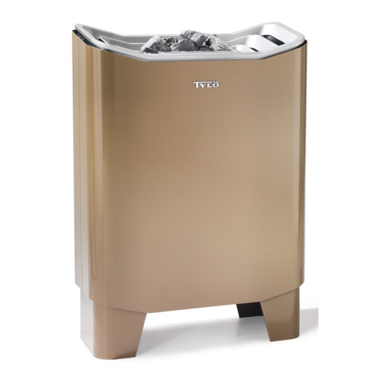
Summary of Contents for Tylo Expression
- Page 1 130404 Expression Art.nr 2900 6110...
-
Page 2: Installation
When the Expression sauna heater is installed in a recess, the sensor WARNING! (C) should be positioned 250 mm from the rear wall and 300 mm from the ceiling. Check before each use of the sauna that there are no foreign objects in •... -
Page 3: Building Instructions
CC 300. Built-in weekly time switch. Manual and automatic on/off. BUILDING INSTRUCTIONS Max. 24 hours connection time, 24 hours preselected time. Fig. 24 - wiring diagram It is important to install correct sauna ventilation. 1 = sauna heater. 2 = thermistor (sensor). 3 = control panel. Incorrect sauna ventilation can result in hot floors and benches and 4 = external on/off switch (option). -
Page 4: General Information
Time setting on control panel TS 16-3(B), TS 30-03 • There should never be a drain in a sauna. However, all public and Expression sauna heater. saunas should have a drainage channel (I, fig. 19) connected to a The first digits 1-2-3 indicate the connection time. The subsequent 9 drain outside the sauna (private saunas do not need a drainage digits indicate the preselected time. - Page 5 CC 100 INFO MENU TEMP LIGHT EC50 TIME TEMP A = min. 400mm B = min. 200mm Min. 100 mm Min. Max. 250 mm Max. 1000 mm...
- Page 6 50-150cm 300mm 50-150cm 300mm Expression + CC/h1/EC50 Expression + h1 Expression + CC/h1/EC50/TS Expression + h1...
- Page 8 Sauna Alt A Alt B A = min. 200 mm B = min. 400 mm Max 400 mm Min 20 mm...
- Page 9 400 - 415 - 440 V 3N~ 1 = Expression 10 2 = thermistor (sensor) 11 12 13 14 15 16 11 12 13 14 15 16 17 18 19 20 21 3 = CC/h1/EC50 4 = external switch 5 = RB 30...


Need help?
Do you have a question about the Expression and is the answer not in the manual?
Questions and answers