Table of Contents
Advertisement
Advertisement
Table of Contents

Related Manuals for Tylo SENSE COMBI


Summary of Contents for Tylo SENSE COMBI
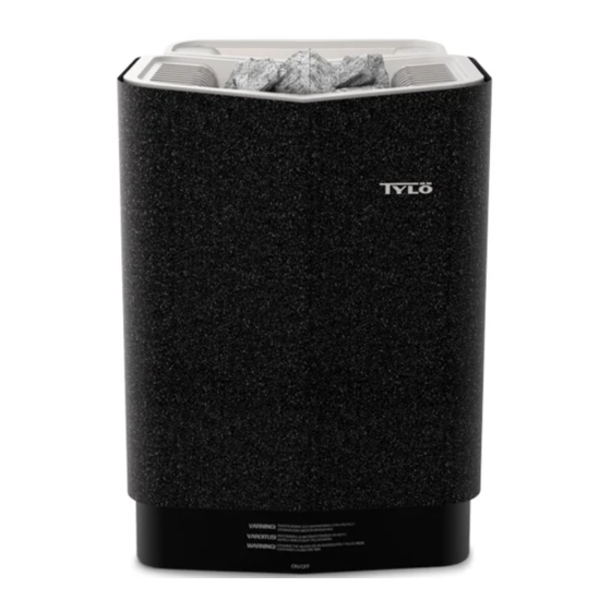
- Page 1 1311 ENGLISH INSTALLATION GUIDE SENSE COMBI 29005195 -ENG...
-
Page 2: Table Of Contents
TABLE OF CONTENTS Before installation ............1 Parts ..................1 Installation requirements ............1 Installation tools ..............2 Planning installation ............... 2 Installation ..............4 Sauna heater installation ............4 Installation of control panel ...........6 External ON/OFF switch (option) ........... 7 Extra control panel (option) ............7 Connection/wiring diagram ........... -
Page 3: Before Installation
BEFORE INSTALLATION To ensure safe use of the heater, check that the following criteria are met: • The sauna cabin should meet the requirements for ceiling Parts height and dimensions according to: "Building a sauna.pdf". Check that the following parts are included in the packaging: •... -
Page 4: Installation Tools
Installation tools Position the sauna heater: • on the same wall as the door (or the side wall if very close to The following tools and materials are needed for installation and the door wall). The heater can also be positioned in a recess connection: (see Figure 5, Page 3). - Page 5 Positioning the control panel The control panel must be correctly positioned with regard to safety distances. Figure 4: Sensor installation on ceiling on centreline of heater as seen from the front and side 200 mm Positioning the heater - recess installation Figure 6: Safety distance, control panel To position the sauna heater in a recess: Heater...
-
Page 6: Installation
INSTALLATION Sauna heater installation It is easiest to prepare for installation with the heater lying down. To install the heater: 1. Lay the heater down front upwards. 2. Slacken the screws and open the cover (see Figure 8, Page Figure 7: Positioning the inlet and outlet vents Inlet vent position. - Page 7 Connect the electrical cable (1) to terminal (2) (see Figure 8. Attach the bracket and spacers to the wall following the spe- 9, Page 5) according to wiring diagram (see The section cified dimensioning (see Figure 10, Page 5). called Connection/wiring diagram, Page 8). Figure 9: Circuit board Electrical cable Terminal for connection of electrical cable...
-
Page 8: Installation Of Control Panel
Unusual voltages/numbers of phases 10. Fit the spacers between heater and wall (to prevent the heater from being lifted off) (see Figure 12, Page 6). Before connecting to voltages or numbers of phases not listed in the wiring diagram Figure 19, Page 8, contact Tylö Customer Service. -
Page 9: External On/Off Switch (Option)
Alternative cabling: e.g. external cabling: drill a small hole in Additional ON/OFF switches must be connected in parallel. Sev- the bottom edge of the plastic cover for external cabling, for eral individual units can be started or stopped via a single extern- the cable to go into the wall (see Figure 16, Page 7). -
Page 10: Connection/Wiring Diagram
CONNECTION/WIRING DIAGRAM Output kW Voltage Amperage Wiring area mm² 400V 3N~ 400V 3N~ 1 2 3 4 Figure 19: Wiring diagram Heater Terminal for connection of electrical cable Control panel Terminal for connection of control panels Sensor/sensor cable Terminal for connection of sensor Light/terminal for connection of light... -
Page 11: Checking Installation
CHECKING INSTALLATION To check the installation: 1. Switch heater on (see User Guide). 2. Check that the control panel lights up . 3. Start the heater (see User Guide). 4. Check that all three tubular elements start to heat up (go red).
Need help?
Do you have a question about the SENSE COMBI and is the answer not in the manual?
Questions and answers