Table of Contents
Advertisement
Advertisement
Table of Contents

Related Manuals for Lenze 8200 series


Summary of Contents for Lenze 8200 series
- Page 1 Artisan Technology Group is your source for quality new and certified-used/pre-owned equipment SERVICE CENTER REPAIRS WE BUY USED EQUIPMENT • FAST SHIPPING AND DELIVERY Experienced engineers and technicians on staff Sell your excess, underutilized, and idle used equipment at our full-service, in-house repair center We also offer credit for buy-backs and trade-ins •...
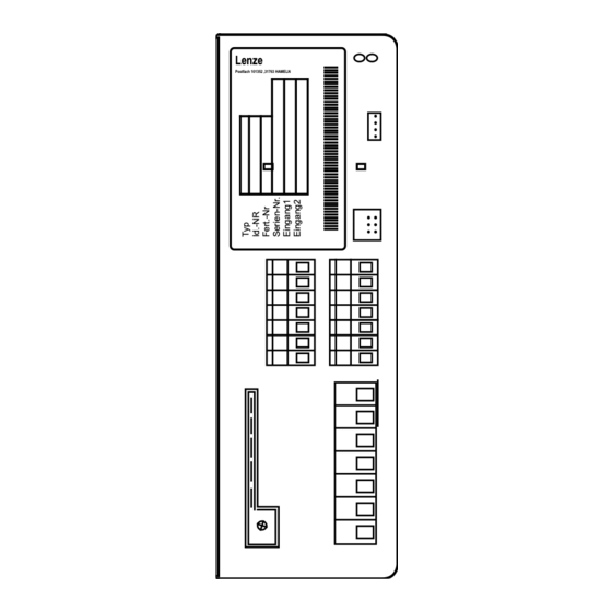
- Page 2 EDB8200EN !NIi Operating Instructions Lenze Postfach 101352 ,31763 HAMELN hPRKMNNMJP Global Drive Frequency inverters 8200 series Artisan Technology Group - Quality Instrumentation ... Guaranteed | (888) 88-SOURCE | www.artisantg.com...
- Page 3 qÜÉëÉ léÉê~íáåÖ fåëíêìÅíáçåë ~êÉ î~äáÇ Ñçê íÜÉ UOuu ÅçåíêçääÉêë çÑ íÜÉ îÉêëáçåëW 33.820X- (8201 - 8204) 33.8202- -V002 reduced assembly depth (8202) Type Design: B = Module C = Cold Plate E = Enclosure IP20 Hardware level and index Software level and index Variant Explanation êÉîáëÉÇ...
-
Page 4: Table Of Contents
Contents 1 Preface and general information ......1.1 About these Operating Instructions ......1.1.1 Terminology used . - Page 5 Contents 5 Commissioning ......... 5.1 Before you switch on .
-
Page 6: Preface And General Information
Any frequency inverter of the series 8200, 8210, 8220, 8240 Controller 82XX frequency inverter Drive system Drive systems with 82XX frequency inverters and other Lenze drive components UOMu_^MVMO Artisan Technology Group - Quality Instrumentation ... Guaranteed | (888) 88-SOURCE | www.artisantg.com... -
Page 7: What Is New
After receipt of the delivery, check immediately whether the scope of supply matches with the accompanying D 1 Operating Instructions papers. Lenze does not accept any liability for deficiencies D 1 accessory kit (components for claimed subsequently. the mechanical and electric... -
Page 8: Legal Regulations
1.3 Legal regulations Labelling Labelling Nameplate CE mark Manufacturer Lenze controllers are Conforms to the EC Low Voltage Lenze Drive Systems GmbH unambiguously designated by Directive Postfach 10 13 52 the content of the nameplate D-31763 Hameln Application 82XX frequency inverter as directed D must only be operated under the conditions prescribed in these Instructions. - Page 9 Operating Instructions. D The specifications, processes, and circuitry described in these Operating Instructions are for guidance only and must be adapted to your own specific application. Lenze does not take responsibility for the suitability of the process and circuit proposals.
-
Page 10: Safety Information
Safety information 2 Safety information 2.1 General safety information Safety and application notes for controllers EíçW içïJsçäí~ÖÉ aáêÉÅíáîÉ TPLOPLbb`F 1. General to the regulations of the EC Directive 89/392/EEC (Machinery Directive); EN 60204 must be observed. During operation, drive controllers may have, according Commissioning (i.e. - Page 11 Safety information Drive controllers contain electrostatically sensitive 6. Operation components which can easily be damaged by Systems where drive controllers are installed must be inappropriate handling. Electrical components must not equipped, if necessary, with additional monitoring and be damaged or destroyed mechanically (health risks are protective devices according to the valid safety possible!).
-
Page 12: Layout Of The Safety Information
Safety information 2.2 Layout of the safety information D ^ää ë~ÑÉíó åçíÉë Ü~îÉ ~ ìåáÑçêã ä~óçìíW J qÜÉ áÅçå ÅÜ~ê~ÅíÉêáòÉë íÜÉ íóéÉ çÑ Ç~åÖÉêK J qÜÉ ëáÖå~ä ïçêÇ ÅÜ~ê~ÅíÉêáòÉë íÜÉ ëÉîÉêáíó çÑ Ç~åÖÉêK J qÜÉ åçíÉ ÇÉëÅêáÄÉë íÜÉ Ç~åÖÉê ~åÇ ëìÖÖÉëíë Üçï íç ~îçáÇ íÜÉ... -
Page 13: Residual Hazards
Safety information 2.3 Residual hazards Operator’s safety After mains disconnections, the power terminals U, V, W and +U , -U remain live for at least three minutes. D Before working on the controller, check that no voltage is applied to the power terminals. Protection of Cyclic connection and disconnection of the controller supply voltage at L1, L2, L3 or +U devices... -
Page 14: Technical Data
Technical Data 3 Technical data 3.1 General data/application conditions Field Values Vibration resistance Germanischer Lloyd, general conditions Humidity class Humidity class F without condensation (average relative humidity 85 %) Permissible Permissible -25 ° C ¼ +70 ° C during transport of the controller: temperature ranges during storage of the controller: -25 °... -
Page 15: Types 8201 To 8204
Technical Data 3.2 Rated data (Operation with 150 % overload) 3.2.1 Types 8201 to 8204 150 % overload Type 8201 8202 8203 8204 Order no. EVF8201-E EVF8202-E EVF8203-E EVF8204-E Variant ”reduced assembly Variant reduced assembly Type 8202-V002 d th” depth” Order no. - Page 16 Technical Data 150 % overload Type 8201 8202 8203 8204 Order no. EVF8201-E EVF8202-E EVF8203-E EVF8204-E Variant ”reduced assembly Variant ”reduced assembly Type 8202-V002 depth” depth” Order no. EVF8202-E- V002 40 ° C < T < 50 ° C: 2,5%/K Power derating [%/K] [%/m]...
-
Page 17: Fuses And Cable Cross-Sections
Technical Data 3.3 Fuses and cable cross-sections 3.3.1 Single drives with 150 % overload qÜÉ í~ÄäÉ î~äìÉë ~êÉ î~äáÇ Ñçê íÜÉ çéÉê~íáçå çÑ UOuu ÅçåíêçääÉêë ~ë ëáåÖäÉ ÇêáîÉë ïáíÜ ~ ã~íÅÜáåÖ ãçíçê ~åÇ NRM B çîÉêäç~ÇK Type Type Mains input L1, N, PE / motor connection U, V, W, PE Operation without mains filter/mains choke Operation with mains filter/mains choke Fuse... -
Page 18: Installation
Installation 4 Installation 4.1 Mechanical installation 4.1.1 Important notes D rëÉ íÜÉ ÅçåíêçääÉêë çåäó ~ë ÄìáäíJáå ÇÉîáÅÉë> D fÑ íÜÉ ÅççäáåÖ ~áê Åçåí~áåë éçääìí~åíë EÇìëíI ÑäìÑÑI ÖêÉ~ëÉI ~ÖÖêÉëëáîÉ Ö~ëÉëFW J í~âÉ ëìáí~ÄäÉ éêÉîÉåíáîÉ ãÉ~ëìêÉë I ÉKÖK ëÉé~ê~íÉ ~áê ÇìÅíI áåëí~ää~íáçå çÑ ÑáäíÉêëI êÉÖìä~ê ÅäÉ~åáåÖI ÉíÅK D lÄëÉêîÉ... - Page 19 Installation Possible mounting positions D få îÉêíáÅ~ä éçëáíáçå ~í íÜÉ Ä~Åâ çÑ íÜÉ Åçåíêçä Å~ÄáåÉíI íÉêãáå~äë éçáåí íç íÜÉ ÑêçåíW J táíÜ ~íí~ÅÜÉÇ ÑáñáåÖ ê~áäëK J táíÜ ëéÉÅá~ä ÑáñáåÖ ìåáí çå çåÉ çê íïç afk ê~áäëK D qìêåÉÇ Äó VM° EÑä~í ~ëëÉãÄäó çå íÜÉ Ä~ÅâëáÇÉ çÑ íÜÉ Åçåíêçä Å~ÄáåÉíFW J fåëÉêí...
-
Page 20: Standard Assembly With Fixing Rails Or Fixing Angles
Installation 4.1.2 Standard assembly with fixing rails or fixing angles 4.1.2.1 Types 8201 to 8204 Lenze P o st fac h10 135 2 , 3 17 63 H AM EL N hPRKMMTQ cfd QJN aáãÉåëáçåë UOMN J UOMQW pí~åÇ~êÇ ~ëëÉãÄäó... -
Page 21: Type 8202-V002 (Reduced Assembly Depth)
Installation 4.1.2.2 Type 8202-V002 (reduced assembly depth) qÜáë î~êá~åí áë ÉèìáééÉÇ ïáíÜ ~ ÜÉ~í ëáåâ ïáíÜ ~ ëã~ääÉê ëìêÑ~ÅÉK lÄëÉêîÉ íÜÉ ÑçääçïáåÖ éçáåíë íç Åçãéäó ïáíÜ íÜÉ íÉÅÜåáÅ~ä Ç~í~W D ^ëëÉãÄäó çå ~å ìåé~áåíÉÇI ãÉí~ääáÅ ~ëëÉãÄäó Äç~êÇK D ^êÉ~ [ MKNR ã D pÜÉÉí... -
Page 22: Din-Rail Assembly
Installation 4.1.3 DIN-rail assembly Le nze P os t fac h 101 352,3176 3 H AMELN > hPRKMMTN cfd QJO aáãÉåëáçåë UOMN J UOMQW afkJê~áä ~ëëÉãÄäó 8201/8202: Assembly on a DIN rail (middle) or on two DIN rails (top and bottom) possible 8203 - 8204: Assembly on two DIN rails Observe the free space required for the connection cables With attachable fieldbus or I/O module:... -
Page 23: Electrical Installation
With isolated neutral Operation with recommended D Mains filter will be destroyed if (IT mains) mains filters is not possible ”earth fault” occurs. D Contact Lenze. With grounded phase Operation only possible with one Contact Lenze variant DC supply via +U... -
Page 24: Power Connections
Installation 4.2.2 Power connections 4.2.2.1 Mains connection D `çååÉÅí íÜÉ ã~áåë Å~ÄäÉë ïáíÜ íÜÉ ëÅêÉï íÉêãáå~äë iNI iOI iPK J qáÖÜíÉåáåÖ íçêèìÉë Terminals L1, L2, L3, +UG, -UG PE connection Type 8201 - 8204 0.5 ... 0.6 Nm (4.4 ... 5.3 lbin) 3.4 Nm (30 lbin) 4.2.2.2 Motor connection _ÉÅ~ìëÉ... - Page 25 Installation D qÜÉ ãçíçê Å~ÄäÉ ëÜçìäÇ ÄÉ ~ë ëÜçêí ~ë éçëëáÄäÉ ÄÉÅ~ìëÉ çÑ íÜÉ éçëáíáîÉ ÉÑÑÉÅí çå íÜÉ ÇêáîÉ ÅÜ~ê~ÅíÉêáëíáÅK J cfd QJP ëÜçïë íÜÉ êÉä~íáçå ÄÉíïÉÉå ãçíçêJÅ~ÄäÉ äÉåÖíÜ ~åÇ íÜÉ éçëëáÄäÉ êÉèìáêÉÇ çìíéìí ÑáäíÉêëK J cçê Öêçìé ÇêáîÉë EëÉîÉê~ä ãçíçêë ÅçååÉÅíÉÇ íç çåÉ ÅçåíêçääÉêF áí...
-
Page 26: Connection Diagram
Installation 4.2.2.3 Connection diagram Fuse N/L2 F2* Fuse only for supply with 2AC / PE / 190-260V K10 Mains contactor K10* Mains contactor only for supply with 2AC / PE / 190-260V Mains filter/mains choke, see Accessories K10* Motor filter/sine filter, see Accessories Brake chopper/brake module, see Accessories... -
Page 27: Control Connections
Installation 4.2.3 Control connections 4.2.3.1 Control cables D tÉ êÉÅçããÉåÇ íÜÉ ìåáä~íÉê~ä ëÅêÉÉåáåÖ çÑ ~ää Å~ÄäÉë Ñçê ~å~äçÖ ëáÖå~äë íç ~îçáÇ ëáÖå~ä ÇáëíçêíáçåK D `çååÉÅí íÜÉ ëÅêÉÉåë çÑ íÜÉ Åçåíêçä Å~ÄäÉë ~ë ÑçääçïëW J UOMuW lå íÜÉ Ñêçåí c^pqJlk ÅçååÉÅíçêK D fÑ... - Page 28 Installation Terminal Level Data (Factory setting is printed in bold) Analog GND 1 inputs Setpoint input, 5 - 6 0 to 20 mA Resolution: 9 bit reference: 5 - 6 4 to 20 mA Linearity fault: ± 0.5 % Terminal 7 3 - 4 0 to 5 V Temperature fault: 0.3 % (0...+40...
-
Page 29: Connection Diagrams
Installation 4.2.3.3 Connection diagrams 82XX GND 2 GND 1 Vref 3k 3k 5,2V 9 K11 K12 K14 20 28 E1 E2 E3 E4 39 hPRKMMTTJP R ³ 1k cfd QJS `çåíêçä ÅçååÉÅíáçåëW pìééäó ïáíÜ áåíÉêå~ä Åçåíêçä îçäí~ÖÉ 82XX GND 2 GND 1 Vref 3k 3k... -
Page 30: Installation Of A Ce-Typical Drive System
Installation 4.3 Installation of a CE-typical drive system General D The user is responsible for the compliance of his application with the EC directives. notes - If you observe the following measure you can be sure that the drive system will not cause any EMC problems, i.e. - Page 31 Installation Screening D Connect the screen of the motor cable with the controller - to the screen connection of the controller. - additionally to the mounting plate with a surface as large as possible. - Recommendation: For the connection, use ground clamps on bare metal mounting surfaces. D If contactors, motor-protecting switches or terminals are located in the motor cable: - Connect the screens of the connected cables also to the mounting plate, with a surface as large as possible.
- Page 32 Installation Netz 82XX GND 2 GND 1 RB1 RB2 +UG -UG Vref 20 28 E1 E2 E3 E4 39 U V W K11 K12 K14 hPRKMMUO cfd QJU bñ~ãéäÉ Ñçê ~å áåëí~ää~íáçå áå ~ÅÅçêÇ~åÅÉ ïáíÜ íÜÉ bj` êÉÖìä~íáçåëW Fuse Mains contactor Mains filter ”A”...
- Page 33 Installation UOMu_^MVMO 4-16 Artisan Technology Group - Quality Instrumentation ... Guaranteed | (888) 88-SOURCE | www.artisantg.com...
-
Page 34: Commissioning
Commissioning 5 Commissioning qÜÉ ÅçåíêçääÉêë ~êÉ Ñ~ÅíçêóJëÉí íç ÇêáîÉ ~ ÅçêêÉëéçåÇáåÖ ÑçìêJéçäÉ ëí~åÇ~êÇ ãçíçê ïáíÜ OPMLQMMsI RMeòK cìêíÜÉê ëÉííáåÖë ~êÉ åçí åÉÅÉëë~êóK låäó ~ ÑÉï ëÉííáåÖë îá~ íÜÉ UOMN __ çéÉê~íáåÖ ãçÇìäÉ çê ~ ÑáÉäÇÄìë ãçÇìäÉ ~êÉ åÉÅÉëë~êó íç ~Ç~éí óçìê ÇêáîÉ íç óçìê ~ééäáÅ~íáçåK qÜÉ ëíÉéë... -
Page 35: Short Set-Up (Factory Setting)
Commissioning 5.2 Short set-up (Factory setting) 5.2.1 Switch-on sequence Step 1.Switch on mains voltage 2.Select the direction of rotation. D CW rotation: - Apply a LOW signal to terminal E4 (0...+3V). D CCW rotation: - Apply a HIGH signal to terminal E4 (+12...+30V). 3.Select the setpoint. -
Page 36: Factory Setting Of The Most Important Drive Parameters
Commissioning 5.2.2 Factory setting of the most important drive parameters Setting Code Factory setting Adaption to application Operating mode C001 Setpoint selection via terminal 8 See code table, Control via terminals chapter 7.2 Parameter setting via 8201BB Terminal configuration C007 See code table, CW/CCWDC injection brake JOG1/2/3... -
Page 37: Adapt Machine Data
Commissioning 5.3 Adapt machine data 5.3.1 Determine speed range (f dmin, dmax) Code Name Possible settings IMPORTANT Lenze Selection Info C010 Minimum field {0.1Hz} 480.0 frequency C011 Maximum field 50.0 30.0 {0.1Hz} 480.0 frequency Function The speed range required for the application can be selected here by determing the... - Page 38 Commissioning Important D With the setting of f > f the field frequency is limited to f dmin dmax dmax D When selecting the setpoint by means of JOG values, f acts as limitation. dmax is an internal standardization variable: dmax - Use the LECOM interface only for important modifications, when the controller is inhibited.
-
Page 39: Adjustment Of Acceleration And Deceleration Times (Tir , T If)
Commissioning 5.3.2 Adjustment of acceleration and deceleration times (T Code Name Possible settings IMPORTANT Lenze Selection Info C012 Acceleration time {0.1s} 999.0 T C013 Deceleration time {0.1s} 999.0 T Function The accleration and deceleration times determine the time required by the drive to follow a setpoint change. -
Page 40: Setting Of The Current Limit (Imax)
Commissioning 5.3.3 Setting of the current limit (I Code Name Possible settings IMPORTANT Lenze Selection Info C022 I limit {1 %} motor mode C023 I limit {1 %} generator mode Function The controllers are equipped with a current-limit control which determines the dynamic response under load. -
Page 41: Optimisation Of The Operating Characteristic Of The Drive
ÄççëíÒK få ÅÜ~éíÉê RKQKN óçì ïáää ÑáåÇ ëçãÉ ãçêÉ ãáå áåÑçêã~íáçå íç ÜÉäé óçì ïáíÜ íÜÉ ëÉäÉÅíáçåK 5.4.1 Select the control mode Code Name Possible settings IMPORTANT Lenze Selection Info C014 ¿ Operating mode Linear characteristic V ~ f with Control auto boost modes of the voltage... - Page 42 Commissioning C014 = -0- C014 = -1- Linear characteristic Square-law characteristic (e. g. for pumps, fans) V o u t V o u t 1 0 0 % 1 0 0 % A u t o b o o s t V m i n A u t o b o o s t...
- Page 43 Commissioning Help for decision Motor cable screened ≤ 25 m screened > 25 m unscreened ≤ 50 m unscreened > 50 m C014 recommended alternatively recommended alternatively Single drives With constant load With changing loads With heavy start conditions High dynamic posotioning and feed drives Lifts and hoists Pumps and fan drives Three-phase reluctance motors...
- Page 44 Commissioning 5.4.1.1 Optimisation of V/f-characteristic control with auto boost Codes required Code Name Possible settings IMPORTANT Lenze Selection Info C015 V/f-rated 50.0 30.0 {0.1Hz} 960.0 frequency C016 V setting {1 %} * type dependent C021 Slip {1 %} compensation Setting sequence 1.If necessary, select V/f...
- Page 45 Commissioning 3.Set the Vmin boost Load-dependentboost of the motor voltage in the field-frequency range below the (C016). V/f-rated frequency. C016 acts as gain factor of the auto-boost function. Adjustment In general, an adjustment is not necessary. An optimisation can be advantageous: For drives with very high starting torques: A Operate the motor under load.
-
Page 46: Optimisation Of V/F-Characteristic Control
Commissioning 5.4.1.2 Optimisation of V/f-characteristic control Codes required Code Name Possible settings IMPORTANT Lenze Selection Info C015 V/f-rated 50.0 30.0 {0.1Hz} 960.0 frequency C016 V setting {1 %} * type dependent C021 Slip {1 %} compensation Setting sequence 1.If necessary, select V/f characteristic (C014). - Page 47 Commissioning 3.Set the Vmin boost D Load-independentboost of the motor voltage for field frequencies below the (C016). U/f-rated frequency. You can thus optimize the torque performance of the inverter drive. D It is absolutely necessary to adapt the asynchronous motor used, since otherwise, the motor can be destroyed by overtemperatue: Adjustment Please note the thermal characteristic of the connected motor under small field...
-
Page 48: During Operation
During operation 6 During operation D oÉéä~ÅÉ ÇÉÑÉÅíáîÉ ÑìëÉë ïáíÜ íÜÉ éêÉëÅêáÄÉÇ íóéÉ çåäó ïÜÉå åç îçäí~ÖÉ áë ~ééäáÉÇK qÜÉêÉ ~êÉ åç ÑìëÉë áå íÜÉ ÅçåíêçääÉêK D `óÅäáÅ ã~áåë ëïáíÅÜáåÖW J aç åçí ëïáíÅÜ çå íÜÉ ÅçåíêçääÉê ãçêÉ íÜ~å ÉîÉêó P ãáåìíÉëI çíÜÉêïáëÉ... - Page 49 During operation D fÑ óçì ìëÉ íÜÉ ÑìåÅíáçå `tL``t EëÉäÉÅíáçå çÑ íÜÉ ÇáêÉÅíáçå çÑ êçí~íáçåF ïáíÜ íÜÉ ÅçåÑáÖìê~íáçå `MMT Z JMJ íç JNPJW J qÜÉ ÇêáîÉ Å~å êÉîÉêëÉ íÜÉ ÇáêÉÅíáçå çÑ êçí~íáçå áå íÜÉ ÉîÉåí çÑ ~ ÅçåíêçäJîçäí~ÖÉ Ñ~áäìêÉ çê ~ Å~ÄäÉ ÄêÉ~âK D fÑ...
-
Page 50: Configuration
Configuration 7 Configuration 7.1 Basics D qÜÉ ÅçåÑáÖìê~íáçå çÑ íÜÉ ÅçåíêçääÉê áë ìëÉÇ íç ~Ç~éí íÜÉ ÇêáîÉ íç óçìê ~ééäáÅ~íáçåëK D cçê íÜáëI óçì Ü~îÉ íÜÉ ÑçääçïáåÖ ÑìåÅíáçåë ~î~áä~ÄäÉW J léÉê~íáåÖ ÑìåÅíáçåë J `çåíêçä ÑìåÅíáçå J aáëéä~ó ÑìåÅíáçåë J jçåáíçêáåÖ ÑìåÅíáçåë D qÜÉ... -
Page 51: Code Table
Name Name of the code. 820X Unit-specific setting possibilites (here for 820X). Without unit designation the code is valid for all unit types. Lenze Factory setting of the code The column ”Important” contains further information Selection {1 %} 99 Minimum value... - Page 52 Configuration Code Code Name Name Possible settings IMPORTANT IMPORTANT Lenze Selection Info C001 Operating mode Setpoint selection via term. 8 ¿ Control via terminals Parameter setting via 8201BB Setpoint selection via 8201BB or via LECOM Control via terminals Parameter setting via 8201BB Setpoint selection via term.
- Page 53 Configuration Code Code Name Name Possible settings IMPORTANT IMPORTANT Lenze Selection Info [C007 Terminal D CW = CW configuration rotation CW/CCWDC brake JOG1/2/3 D CCW = CW/CCWPAR JOG1/2/3 CW/CCWQSP JOG1/2/3 rotation CW/CCWPAR DC brake JOG1 D DC brake = CW/CCWQSP...
- Page 54 Configuration Code Code Name Name Possible settings IMPORTANT IMPORTANT Lenze Selection Info C009* Device address Only for LECOM applications C010 Minimum field {0.1Hz} 480.0 frequency C011 Maximum field frequency 820X 50.0 30.0 {0.1Hz} 480.0 821X 50.0 {0.1Hz} 480.0 (Software 2x) 30.0...
- Page 55 Configuration Code Code Name Name Possible settings IMPORTANT IMPORTANT Lenze Selection Info C016 V C016 setting 820X {1 %} * depends on the unit 821X/822X {1 %} / 824X C017 Threshold Q {0.1Hz} 480.0 C018 Chopper ¿ ¿ frequency 821X/822X/824...
- Page 56 Configuration Code Code Name Name Possible settings IMPORTANT IMPORTANT Lenze Selection Info C038 JOG value 2 {1Hz} C039 JOG value 3 {1Hz} C050* Output Only display frequency C052* Motor voltage Only display C054* Motor current Only display C056* Controller load...
- Page 57 Configuration Code Code Name Name Possible settings IMPORTANT IMPORTANT Lenze Selection Info C099* Software version Only display 820X 82 1x (Software 1x) 821X 82 2x (Software 2x) 82 1x (Software 1x) 822X/824X 82 1x (Software 1x) C105 Deceleration time quick stop 5.00...
- Page 58 Configuration Code Code Name Name Possible settings IMPORTANT IMPORTANT Lenze Selection Info C117 Function relay ¿ Ready for operation 822X/824X TRIP fault message Motor is running Motor is running / CW rotation Motor is running / CCW rotation Field frequency f...
- Page 59 {1s} Auto-TRIP-Reset C178* Operating time Only display C179* Mains switch-on Only display time C377 Gain Zk-voltage Should only detection be changed by the Lenze 822X/824X Service! C500* Display factor application datum numerator 821X/822X/824 2000 1 25000 C501* Display factor for process...
-
Page 60: Troubleshooting And Fault Elimination
Troubleshooting and fault elimination 8 Troubleshooting and fault elimination D c~ìäíë ~êÉ áããÉÇá~íÉäó áåÇáÅ~íÉÇ îá~ íÜÉ Çáëéä~ó çê ëí~íìë áåÑçêã~íáçå EÅÜ~éíÉê UKNFK D qÜÉ Ñ~ìäí Å~å ÄÉ ~å~äóëÉÇ Äó ìëáåÖ íÜÉ Üáëíçêó ÄìÑÑÉê EÅÜ~éíÉê UKOF ~åÇ íÜÉ äáëí áå ÅÜ~éíÉê UKPK qÜÉ äáëí ÜÉäéë óçì ïáíÜ íÜÉ Éäáãáå~íáçå... -
Page 61: Maloperation Of The Drive
Troubleshooting and fault elimination 8.1.3 Maloperation of the drive Maloperation Possible causes Motor does not rotate D DC-bus voltage too low (red LED is blinking every 0.4 s; message LU is displayed) D Controller inhibited (green LED is blinking, display of the operating module: OFF, STOP or AS_LC) D Setpoint = 0 D DC braking active... -
Page 62: Fault Indications
No fault External fault (TRIP-Set) A digital input assigned to the Check external encoder TRIP-Set function has been activated Internal fault Contact Lenze Undervoltage DC-bus voltage too low D Check mains voltage D Check supply module Short circuit Short circuit Find out cause of short circuit;... - Page 63 Troubleshooting and fault elimination Display Fault Cause Remedy Heat sink temperature is Ambient temperature D Allow controller to cool and ensure higher than the value set > +40 ° C or +50 ° C ventilation in the controller D Check the ambient temperature in the control cabinet Heat sink very dirty Clean heat sink...
-
Page 64: Reset Of Fault Indications
~ÅâåçïäÉÇÖÉãÉåí çÑ qofmK Note! fÑ íÜÉ qofm ëçìêÅÉ áë ëíáää ~ÅíáîÉI íÜÉ qofm Å~ååçí ÄÉ êÉëÉíK Code Name Possible settings IMPORTANT Lenze Selection Info C170 ¿ TRIP-reset TRIP-reset by pressing the STP selection key or a LOW signal at ctrl. enable... - Page 65 Troubleshooting and fault elimination Function You can select whether the active fault is to be reset automatically or manually. Auto-Trip reset does not reset all faults automatically. Activation C170 = -0-: D Manual TRIP-reset D STP key D LOW signal at terminal 28 C170 = -1-: Auto-Trip reset resets the following fault messages after the time set under C171: - OC3 (overload during acceleration)
-
Page 66: Accessories (Overview)
Accessories 9 Accessories (Overview) 9.1 Accessories for all types Name Order number 8201BB operating module EMZ8201BB Diagnosis terminal (2.5 m cable) EMZ8272BB-V001 Diagnosis terminal (5.0 m cable) EMZ8272BB-V002 Diagnosis terminal (10 m cable) EMZ8272BB-V003 Digital display EPD203 Setpoint potentiometer ERPD0001k0001W Rotary button for potentiometer ERZ0001 Scale for potentiometer... -
Page 67: Software
Accessories 9.2 Software Name Order number PC program for Global Drive controllers ESP-GDC 1 9.3 Type-specific accessories Name Order number 8201 8202 8203 8204 E.l.c.b. EFA1C10A EFA1C16A EFA1C20A EFA1C20A Fuse EFSM-0100ASB EFSM-0150ASB EFSM-0200ASC EFSM-0200ASC Fuse holder EFH30001 EFH30001 EFH30001 EFH30001 Mains filter type “A”... -
Page 68: Index
Index Index Cable cross-sections, Single drives, 3-4 Acceleration times, 5-6 150 % overload, 3-4 Adapt the motor, 5-8 Code table, 7-2 Application, as directed, 1-3 Information on the, 7-2 Application conditions, 2-1 Commissioning, 5-1 Applications as directed, 1-3 Configuration, 7-1 Approvals, 2-1 Acceleration and deceleration times, 5-6 Basic information, 7-1... - Page 69 Index Deceleration times, 5-6 Factory setting Definitions of terminology used, 1-1 Important drive parameters, 5-3 Short set-up, 5-2 Degree of pollution, 2-1 Switch-on sequence, 5-2 Dimensions Fault analysis, 8-2 8202-V002 reduced assembly depth, 4-4 820X with fixing rail, 4-3 Fault messages, 8-3 Controller, 3-4 Reset, 8-5 Display...
- Page 70 Index Mains connection, 4-7 Initial switch-on, 5-1 Mains-voltage compensation, 5-11, 5-13 Inputs Maloperation of the drive, 8-2 Analog, 4-11 Manufacturer, 1-3 Digital, 4-11 Mechanical installation, 4-1 Installation, 4-1 Messages, Fault, 8-3 CE-typical drive system, 4-13 Monitor output, 4-11 Assembly, 4-13 Motor, Adapt, 5-8 Filters, 4-13 Grounding, 4-14...
- Page 71 Index Technical data, 2-1 Rated data, Types 8201-8204, 150 % General data/application conditions, 2-1 overload, 3-2 Temperature ranges, 2-1 Relay output, 4-11 Transport, storage, 2-1 TRIP, 8-5 Reset, Fault message, 8-5 Troubleshooting, 8-1 Residual hazards, 2-4 Display at the operating module , 8-1 Fault analysis using the history buffer , 8-2 Fault indication, 8-3 LED, 8-1...
- Page 72 Index UOMu_^MVMO 10-5 Artisan Technology Group - Quality Instrumentation ... Guaranteed | (888) 88-SOURCE | www.artisantg.com...
- Page 73 Index UOMu_^MVMO 10-6 Artisan Technology Group - Quality Instrumentation ... Guaranteed | (888) 88-SOURCE | www.artisantg.com...
- Page 74 Artisan Technology Group is your source for quality new and certified-used/pre-owned equipment SERVICE CENTER REPAIRS WE BUY USED EQUIPMENT • FAST SHIPPING AND DELIVERY Experienced engineers and technicians on staff Sell your excess, underutilized, and idle used equipment at our full-service, in-house repair center We also offer credit for buy-backs and trade-ins •...
Need help?
Do you have a question about the 8200 series and is the answer not in the manual?
Questions and answers