Table of Contents
Advertisement
Quick Links
© Vallox
1.09.420 EN
14.5.2013
1
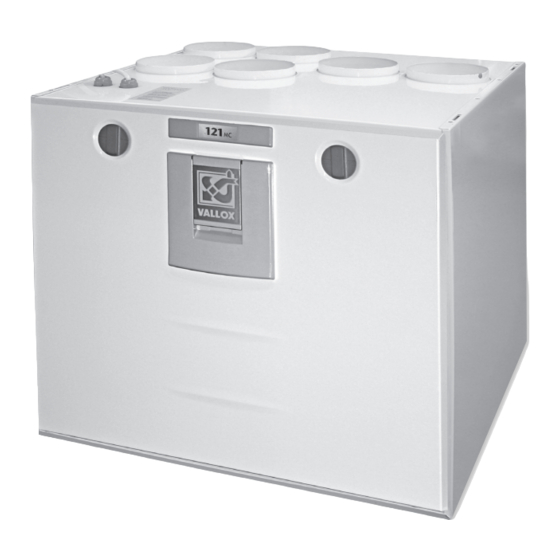
Extract air fan
2
Supply air fan
3
Post-heating radiator
(electric 900 W)
4
Heat recovery cell
5
Outdoor air fi lter F7
6
Outdoor air fi lter G4
7
Extract air fi lter G4
8
Automatic summer/winter damper
9
Safety switch
10 Measurement outlets
(behind an opening door)
11 Adjustment of the relationship
between supply and extract air
12 Adjustment of post-heating
13 Speed selector switch
(1–4, option)
Vallox
121
Low-energy ventilation
unit with heat recovery
Operating, maintenance and technical instructions
10
13
TECHNICAL DATA
Electrical connection
Degree of protection provided by enclosures
Fans
Extract air
direct current (DC) Supply air
Heat recovery
Heat recovery bypass
Electric post-heating unit
Fans
Supply air
Extract air
Weight
Ventilation control
MC
7
8
9
11
12
6
5
4
3
2
The fi gure shows the R model
230V 50Hz = 5.7A
IP 34
0.119 kW 0.9A 105 dm³/s 50Pa
0.119 kW 0.9A 101 dm³/s 50Pa
Cross-counter fl ow heat recovery cell, >80%
Automatic
900 W, 3.9 A
G4 and F7
G4
60 kg
Simple Control controller (option)
PTXPA Slim-Line SC cooker hood (option)
Fireplace switch (option)
Code
3561
Models
VALLOX 121 MC R
VALLOX 121 MC L
1
Advertisement
Table of Contents

Subscribe to Our Youtube Channel
Related Manuals for Vallox 121 MC Series


Summary of Contents for Vallox 121 MC Series
- Page 1 Code 3561 Models Vallox VALLOX 121 MC R VALLOX 121 MC L Low-energy ventilation unit with heat recovery © Vallox Operating, maintenance and technical instructions 1.09.420 EN 14.5.2013 Extract air fan Supply air fan Post-heating radiator (electric 900 W) Heat recovery cell...
-
Page 2: Maintenance Reminder
OPERATING INSTRUCTIONS Fan speed adjustment The fan speed of Vallox ventilation unit can be controlled with a control switch (option), with a separate cooker hood (option) or directly with a 0-10 V voltage signal. Speeds 1, 2, 3 and 4 can be selected at the control switch: Operation during absence. -
Page 3: Troubleshooting
Before starting maintenance operations Disconnect the plug of the VALLOX 121 MC unit before starting maintenance operations. When you open the VALLOX 121 MC unit, the security switch (S) turns voltage off. In spite of this, disconnect the plug of the unit. Filters... -
Page 4: Maintenance Instructions
Clean if needed. Do not let water flow into electrical devices. © VALLOX • We reserve the right to make changes without prior notice. What the units include can vary depending on the sales area. -
Page 5: Technical Data
ADJUSTMENT POSITION/AIR FLOW dm 10.0 11.2 24/26 33/34 40/42 50/51 62/62 71/71 82/82 92/92 , dB (A) © VALLOX • We reserve the right to make changes without prior notice. What the units include can vary depending on the sales area. -
Page 6: Electrical Diagram
Zero voltage to damper motor E/I: Input voltage to fault signal relay E/O: Fault signal relay output © VALLOX • We reserve the right to make changes without prior notice. What the units include can vary depending on the sales area. -
Page 7: Mounting Instructions
VALLOX 121 MC can also be located in a damp room, but not in a bathroom next to a sauna bath. Condensing water connections Wall construction The delivery includes a Silent Kick water seal. - Page 8 Vallox © VALLOX • We reserve the right to make changes without prior notice. What the units include can vary depending on the sales area.
Need help?
Do you have a question about the 121 MC Series and is the answer not in the manual?
Questions and answers