Cisco Catalyst 9404R Switch Hardware Installation Manual
Hide thumbs
Also See for Catalyst 9404R Switch:
- Installation note (32 pages) ,
- Hardware installation manual (192 pages)
Table of Contents
Advertisement
Advertisement
Table of Contents
Troubleshooting

Subscribe to Our Youtube Channel
Related Manuals for Cisco Catalyst 9404R Switch


Summary of Contents for Cisco Catalyst 9404R Switch
- Page 1 Cisco Catalyst 9400 Series Switches Hardware Installation Guide First Published: 2017-09-20 Last Modified: 2018-08-15 Americas Headquarters Cisco Systems, Inc. 170 West Tasman Drive San Jose, CA 95134-1706 http://www.cisco.com Tel: 408 526-4000 800 553-NETS (6387) Fax: 408 527-0883...
-
Page 2: Table Of Contents
Installation Considerations - Power Supply Modules of Different Capacities C H A P T E R 3 Preparing for Installation Safety Warnings Site Requirements Temperature Air Flow Humidity Altitude Dust and Particles Cisco Catalyst 9400 Series Switches Hardware Installation Guide... - Page 3 Installing the Cable Guide Without Shelf Brackets Install the Switch in a NEBS-Compliant Mode NEBS-Compliant Air Filter Rack-Mounting the Chassis in a NEBS-Compliant Mode Establishing System Ground Attaching an ESD Strap Verifying the Switch Chassis Installation Cisco Catalyst 9400 Series Switches Hardware Installation Guide...
- Page 4 Troubleshooting with Software Troubleshooting the Power Supply Useful Cisco IOS Commands - Power Supply Troubleshooting the Fan Tray Assembly Useful Cisco IOS Commands - Fan Tray Assembly Troubleshooting High Temperature Alarms Troubleshooting the Switching Module Useful Cisco IOS Commands - Switching Modules...
- Page 5 Connecting to the Switch Creating User Accounts Choosing Setup Options Configuring Basic Device Settings Configuring Your Device Based on a Site Profile Configuring Switch Wide Settings Configuring VLAN Settings Configure STP Settings Cisco Catalyst 9400 Series Switches Hardware Installation Guide...
- Page 6 Installing the Cisco Microsoft Windows XP USB Driver Installing the Cisco Microsoft Windows 2000 USB Driver Installing the Cisco Microsoft Windows Vista and Windows 7 USB Driver Uninstalling the Cisco Microsoft Windows USB Driver Uninstalling the Cisco Microsoft Windows XP and 2000 USB Driver...
-
Page 7: Safety Warnings
Statement 1051 Warning Class 1M laser radiation when open. Do not view directly with optical instruments. Statement 1053 Warning Class I (CDRH) and Class 1M (IEC) laser products. Statement 1055 Cisco Catalyst 9400 Series Switches Hardware Installation Guide... - Page 8 Viewing the laser output with certain optical instruments (for example, eye loupes, magnifiers, and microscopes) within a distance of 100 mm may pose an eye hazard. Statement 1056 Cisco Catalyst 9400 Series Switches Hardware Installation Guide...
-
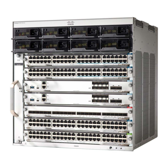
Page 9: Product Overview
Switch Models Catalyst 9404R Switch The Catalyst 9404R Switch is a four-slot modular chassis, with two redundant supervisor module slots, two switching module slots with up to 96 front panel ports, one nonredundant fan tray assembly, and has a provision to accommodate up to four power supply modules. - Page 10 Chassis model number Supervisor module slots (2 and 3) System ground Rear View of the Catalyst 9404R Switch The figure shows a rear view of the chassis, with the major components identified: Cisco Catalyst 9400 Series Switches Hardware Installation Guide...
- Page 11 Table 1: Catalyst 9404R Switch Features Feature Description Product ID C9404R—Cisco Catalyst 9400 Series 4 Slot Chassis C9404R= (Spare) Chassis Has four horizontal slots. Slots are numbered 1 (left) to 4 (right). Cisco Catalyst 9400 Series Switches Hardware Installation Guide...
- Page 12 • Must be installed in slots numbered 2 and 3 only. • Have minimum software release version requirements. Refer to your software release notes for this information. Cisco Catalyst 9400 Series Supervisor Module Installation Note. Cisco Catalyst 9400 Series Switches Hardware Installation Guide...
- Page 13 (C9400-LC-24XS=). • Cisco Catalyst 9400 Series 48-Port UPOE Multigigabit Module (C9400-LC-48UX) and the module spare (C9400-LC-48UX=). • Cisco Catalyst 9400 Series 48-Port SFP Module (C9400-LC-48S) and the module spare (C9400-LC-48S=) • Cisco Catalyst 9400 Series 24-Port SFP Module (C9400-LC-24S) and the module spare (C9400-LC-24S=) •...
-
Page 14: Catalyst 9407R Switch
The figure shows a front view of the chassis, with the major components identified: Chassis handholds Supervisor module slots (3 and 4) Power supply modules Chassis Radio Frequency ID (RFID) Switching module slots (1,2, 5,6, and 7) System ground Cisco Catalyst 9400 Series Switches Hardware Installation Guide... - Page 15 Table 2: Catalyst 9407R Switch Features Feature Description Product ID C9407R—Cisco Catalyst 9400 Series 7 Slot Chassis C9407R= (Spare) Chassis Has seven horizontal slots. Slots are numbered 1 (top) to 7 (bottom) Cisco Catalyst 9400 Series Switches Hardware Installation Guide...
- Page 16 • Must be installed in slots numbered 3 and 4 only. • Have minimum software release version requirements. Refer to your software release notes for this information. Cisco Catalyst 9400 Series Supervisor Module Installation Note Cisco Catalyst 9400 Series Switches Hardware Installation Guide...
- Page 17 (C9400-LC-24XS=). • Cisco Catalyst 9400 Series 48-Port UPOE Multigigabit Module (C9400-LC-48UX) and the module spare (C9400-LC-48UX=). • Cisco Catalyst 9400 Series 48-Port SFP Module (C9400-LC-48S) and the module spare (C9400-LC-48S=) • Cisco Catalyst 9400 Series 24-Port SFP Module (C9400-LC-24S) and the module spare (C9400-LC-24S=) •...
-
Page 18: Catalyst 9410R Switch
Front View of the Catalyst 9410R Switch The figure shows a front view of the chassis, with the major components identified: Cisco Catalyst 9400 Series Switches Hardware Installation Guide... - Page 19 Supervisor module slots (5 and 6) Power supply modules Chassis Radio Frequency ID (RFID) Switching module slots (1,2, 3, 4, 7, 8, 9 and System ground Fan tray assembly Chassis model number Cisco Catalyst 9400 Series Switches Hardware Installation Guide...
- Page 20 Blue beacon LED on the rear of the fan tray (always matches the blue beacon on the front of the fan tray) Table 3: Catalyst 9410R Switch Features Feature Description Product ID C9410R—Cisco Catalyst 9400 Series 10 Slot Chassis C9410R= (Spare) Cisco Catalyst 9400 Series Switches Hardware Installation Guide...
- Page 21 • Must be installed in slots numbered 5 and 6 only. • Have minimum software release version requirements. Refer to your software release notes for this information. Cisco Catalyst 9400 Series Supervisor Module Installation Note Cisco Catalyst 9400 Series Switches Hardware Installation Guide...
- Page 22 (C9400-LC-24XS=). • Cisco Catalyst 9400 Series 48-Port UPOE Multigigabit Ethernet Module (C9400-LC-48UX) and the module spare (C9400-LC-48UX=). • Cisco Catalyst 9400 Series 48-Port SFP Module (C9400-LC-48S) and the module spare (C9400-LC-48S=) • Cisco Catalyst 9400 Series 24-Port SFP Module...
-
Page 23: Fan Tray Assembly
Switches. • Is chassis-specific. (Add = to the model number for spares) • Model number C9404-FAN for the Catalyst 9404R Switch. This model has eight individual fans (two rows of four each). It supports a minimum airflow of 640 cubic feet per minute (CFM) at 100 percent fan throttle. -
Page 24: Operation
Do not operate the system if the fan tray assembly is removed or if it is not functioning properly. An overtemperature condition can cause severe equipment damage or an unscheduled system shutdown. Cisco Catalyst 9400 Series Switches Hardware Installation Guide... -
Page 25: High Availability
• If two or more fans have failed • If the STATUS LED remains red for more than one minute • If there is a hardware failure • If the software watchdog timer is triggered Cisco Catalyst 9400 Series Switches Hardware Installation Guide... -
Page 26: Power Supply Module
The RFID tags are compatible with the Generation 2 GS1 EPC Global Standard and are ISO 18000-6C compliant. They operate in the 860- to 960-MHz UHF band. For more information, see Radio Frequency Identification (RFID) on Cisco Catalyst 9000 Family Switches. Cisco Catalyst 9400 Series Switches Hardware Installation Guide... - Page 27 The power supply connectors distribute power as follows: Module C9400-PWR-3200AC C9400-PWR-2100AC Supervisor Module (Main Output) Maximum of 20A at 55VDC Maximum of 20A at 55VDC Switching Module (Main Output) Maximum of 120A at 55VDC Maximum of 120A at 55VDC Cisco Catalyst 9400 Series Switches Hardware Installation Guide...
-
Page 28: Power Supply Modes
(Standby Output) Power Supply Modes Cisco Catalyst 9400 Series Switches offer redundant and combined configuration modes for power supplies. The number of power supply modules installed and the system load determine the power-level that the system expects to draw from each power supply module and consequently, the power supply mode that will be suitable. -
Page 29: Installation Considerations - Power Supply Modules Of Different Capacities
Installation Considerations - Power Supply Modules of Different Capacities You can install power supplies of different capacities in a Cisco Catalyst 9400 Series chassis. If you do, and you use the default power supply mode, which the combined mode, there are no additional factors to consider. - Page 30 Product Overview Installation Considerations - Power Supply Modules of Different Capacities Cisco Catalyst 9400 Series Switches Hardware Installation Guide...
-
Page 31: Preparing For Installation
Invisible laser radiation may be emitted from disconnected fibers or connectors. Do not stare into beams or view directly with optical instruments. Statement 1051 Warning Class 1M laser radiation when open. Do not view directly with optical instruments. Statement 1053 Cisco Catalyst 9400 Series Switches Hardware Installation Guide... -
Page 32: Site Requirements
Cisco Catalyst 9400 Series Switches Hardware Installation Guide... -
Page 33: Temperature
Figure 3: Air Flow Direction - Cisco Catalyst 9400 Series Switches The figure shows the chassis and power supply air flow directions in a Catalyst 9407R Switch. The same air flow direction applies to all Cisco Catalyst 9400 Series Switches. - Page 34 • If the ambient intake air temperature is less than 109°F (45°C) at altitudes of 6,000 feet and below, the rack meets the intake air temperature criterion. At altitudes above that threshold and up to 10,000 feet (3000 m), the air intake should not exceed 104°F (40°C). Cisco Catalyst 9400 Series Switches Hardware Installation Guide...
-
Page 35: Humidity
The standards listed below provide guidelines for acceptable working environments and acceptable levels of suspended particulate matter: • National Electrical Manufacturers Association (NEMA) Type 1 • International Electrotechnical Commission (IEC) IP-20 Cisco Catalyst 9400 Series Switches Hardware Installation Guide... -
Page 36: Corrosion
Category 5e, Category 6, and Category 6a cables can store large levels of static electricity because of the dielectric properties of the materials used in their construction. Always ground the cables (especially in new cable runs) to a suitable and safe earth ground before connecting them to the module. Cisco Catalyst 9400 Series Switches Hardware Installation Guide... -
Page 37: Shock And Vibration
AC third-prong ground are insufficient to adequately ground the systems. Proper grounding practices ensure that the buildings and the installed equipment within them have low-impedance connections and low-voltage differentials between chassis. When you install a system ground, Cisco Catalyst 9400 Series Switches Hardware Installation Guide... - Page 38 This installation has a coupling from the noise source to the history of malfunction due to victim equipment. electromagnetic noise. Cisco Catalyst 9400 Series Switches Hardware Installation Guide...
-
Page 39: Maintaining Safety With Electricity
• If an electrical accident occurs, proceed as follows: • Use extreme caution; do not become a victim yourself. • Disconnect power from the system. Cisco Catalyst 9400 Series Switches Hardware Installation Guide... -
Page 40: Preventing Electrostatic Discharge Damage
• Use the correct external power source. Operate the product only from the type of power source indicated on the electrical ratings label. If you are not sure of the type of power source required, consult the Cisco Technical Assistance Center or a local electrician. -
Page 41: Power Requirements
• The source AC outlet must be within 9.84 to 14 feet (3.0 to 4.293 meters) of the system, depending on the length of the power cord, and should be easily accessible. Cisco Catalyst 9400 Series Switches Hardware Installation Guide... -
Page 42: Cabling Requirements
We strongly recommend that power cabling runs and other potential noise sources be located as far away as practical from LAN cabling that terminates on Cisco equipment. In situations where this type of long parallel cable runs exist and cannot be separated by at least 3.3 feet (1 meter), we recommend that you shield these potential noise sources. - Page 43 RU or 42 U in height. The chassis heights are as follows: • The Catalyst 9404R Switch chassis height—10.5 inches (26.67 cms)—6 RU. • The Catalyst 9407R Switch chassis height—17.41 inches (44.22 cms)—10 RU. • The Catalyst 9410R Switch chassis height—22.61 inches (57.43 cms)—13 RU.
-
Page 44: Site Preparation Checklist
• Power receptacles (Depends on power supply) • Receptacle proximity to the equipment. • Dedicated (separate) circuits for redundant power supplies. • UPS for power failures Grounding evaluation • Circuit breaker size • CO ground (AC powered systems) Cisco Catalyst 9400 Series Switches Hardware Installation Guide... - Page 45 Refer to the power supply'VA rating as a sizing criteria in determining the output required by the UPS. The power supply kVA rating value is listed in the specifications table for each power supply in Appendix A (power supply specifications). Cisco Catalyst 9400 Series Switches Hardware Installation Guide...
- Page 46 Preparing for Installation Site Preparation Checklist Cisco Catalyst 9400 Series Switches Hardware Installation Guide...
-
Page 47: Standard Accessory Kit Contents
Catalyst 9407R Switch C9407-ACC-KIT= Catalyst 9410R Switch C9410-ACC-KIT= Cisco Catalyst 9400 Series Switches ship with a standard accessory kit, which includes the following items: Item Quantity 12-24 x 0.75 inch M, Phillips screws 10-32 x 0.75 inch M, Phillips screws... - Page 48 Standard Accessory Kit Contents Cisco Catalyst 9400 Series Switches Hardware Installation Guide...
-
Page 49: Installing The Switch
Statement 1024 Warning This unit might have more than one power supply connection. All connections must be removed to de-energize the unit. Statement 1028 Cisco Catalyst 9400 Series Switches Hardware Installation Guide... - Page 50 The process of installing the switch can be broken down into a series of tasks as shown in the following figure: Note This section illustrates the installation of a Catalyst 9407R Switch switch. All Cisco Catalyst 9400 Series Switches are installed in the equipment rack the same way.
-
Page 51: Unpacking The Switch
Step 2 Check the modules in each slot. Ensure that the configuration matches the packing list and that all of the specified interfaces are included. Step 3 Store the shipping carton. Cisco Catalyst 9400 Series Switches Hardware Installation Guide... -
Page 52: Install The Switch As Shipped
Insert the rear of the chassis between the mounting posts of the rack. Step 2 Align the mounting holes in the L bracket on the switch with the mounting holes in the equipment rack. Cisco Catalyst 9400 Series Switches Hardware Installation Guide... - Page 53 Rack-Mounting the Chassis as Shipped Figure 5: Securing the Chassis to the Rack Posts Step 3 Secure the chassis to the rack with either 10-32 or 12-24 pan head screws from the chassis standard accessory kit. Cisco Catalyst 9400 Series Switches Hardware Installation Guide...
- Page 54 3. Connecting the network interface cables to the supervisor module and line card modules. This may involve installing transceivers before you attach the network interface cables. 4. Powering up the chassis and verifying the installation. Cisco Catalyst 9400 Series Switches Hardware Installation Guide...
-
Page 55: Install The Switch With Shelf Brackets
12-24 x 0.75-inch Phillips screws 10-32 x 0.75-inch Phillips screws M4 x 8 mm Phillips flat head screws Documentation, pointer card Provides references to related documentation on cisco.com Cisco Catalyst 9400 Series Switches Hardware Installation Guide... -
Page 56: Installing The Shelf Kit L Brackets
Remove and discard the L brackets and the ten mounting screws that the chassis is shipped with. Do not re-use them during any part of the installation process. Figure 7: L Brackets the Chassis is Shipped With L Brackets that the chassis is shipped with Cisco Catalyst 9400 Series Switches Hardware Installation Guide... - Page 57 Installing the Switch Installing the Shelf Kit L Brackets Figure 8: Removing L Brackets the Chassis is Shipped With Cisco Catalyst 9400 Series Switches Hardware Installation Guide...
- Page 58 Step 3 Using the M4 x 8 mm Phillips flat head screws in the shelf kit, secure the L brackets to the front-left and front-right sides of the chassis (four on each side). Cisco Catalyst 9400 Series Switches Hardware Installation Guide...
-
Page 59: Installing The Shelf Brackets
Install the shelf brackets before you install the chassis in the rack. The shelf brackets attach directly to the rack and help support the weight of the chassis while you secure the L brackets to the rack enclosure. You have to front-mount the shelf brackets. Cisco Catalyst 9400 Series Switches Hardware Installation Guide... - Page 60 Figure 11: Installing the Shelf Brackets Shelf brackets Pan head screws from the shelf kit that secure the shelf brackets to the rack posts The shelf brackets are now securely mounted to the rack posts Cisco Catalyst 9400 Series Switches Hardware Installation Guide...
-
Page 61: Rack-Mounting The Chassis
• Cable guide installation options have been described in a separate topic. If you are installing the cable guide, read this procedure and the cable guide installation procedure, before you start. Procedure Step 1 Pull out all four of the handholds Cisco Catalyst 9400 Series Switches Hardware Installation Guide... - Page 62 Rest the back end of the chassis on the edges of the shelf bracket rails and slide it in until the first pair of handles on both sides of the chassis are near the rack posts. Step 4 Push in the handholds that are closest to the rack posts Cisco Catalyst 9400 Series Switches Hardware Installation Guide...
- Page 63 Figure 13: Sliding the Chassis in - Part 1 Handholds closest to the rack posts, pushed Step 5 Continue sliding the chassis in until the second pair of handholds are near the rack posts Cisco Catalyst 9400 Series Switches Hardware Installation Guide...
- Page 64 Push in the the second pair of handholds and continue sliding the chassis in until the L brackets make contact with the rack posts. Step 7 Secure the chassis to the rack with either the 10-32 or 12-24 pan head screws from the chassis standard accessory kit. Cisco Catalyst 9400 Series Switches Hardware Installation Guide...
- Page 65 Installing the Switch Rack-Mounting the Chassis Figure 15: Securing the Chassis to the Rack Posts Cisco Catalyst 9400 Series Switches Hardware Installation Guide...
- Page 66 What to do next After installing the chassis in its location, complete the installation process by: 1. Connecting the chassis to system ground. 2. Installing and connecting the power supplies to the power source. Cisco Catalyst 9400 Series Switches Hardware Installation Guide...
-
Page 67: Installing The Cable Guide
You can install cable guides with or without the shelf brackets. Follow the corresponding procedure: Note Cable guides are part of the standard accessory kit. Installing the Cable Guide With Shelf Brackets Procedure Step 1 Mount the shelf brackets with only two screws on each side Cisco Catalyst 9400 Series Switches Hardware Installation Guide... - Page 68 Using one screw on each side, align the cable guide mounting holes with the shelf bracket holes and the rack rail holes, Using two screws on each side, align the cable guide mounting holes with the L bracket holes and the rack rail holes. Cisco Catalyst 9400 Series Switches Hardware Installation Guide...
- Page 69 L for the shelf bracket and two on each side bracket. for the L bracket. Cable guide installation with shelf brackets is complete. Cisco Catalyst 9400 Series Switches Hardware Installation Guide...
-
Page 70: Installing The Cable Guide Without Shelf Brackets
Installing the Cable Guide Without Shelf Brackets Procedure Step 1 Secure the chassis to the rack rails with only two screws on each side. Step 2 Position the cable guides and align with the L brackets. Cisco Catalyst 9400 Series Switches Hardware Installation Guide... - Page 71 L bracket to the rack rails. Cable guide installation without shelf brackets is complete. Cisco Catalyst 9400 Series Switches Hardware Installation Guide...
-
Page 72: Install The Switch In A Nebs-Compliant Mode
A 23-inch rack mount is used for mounting the switch in a standard 23 inch (58.4 cm) equipment rack with two unobstructed outer posts. This kit is not suitable for racks with obstructions (such as a power strip) that could impair access to the field-replaceable units (FRUs) of the switch. Cisco Catalyst 9400 Series Switches Hardware Installation Guide... -
Page 73: Rack-Mounting The Chassis In A Nebs-Compliant Mode
• Place the chassis on the floor or on a sturdy table as close as possible to the rack. Leave enough clearance to allow you to move around the chassis. • Open the rack-mount kit and verify that all parts are included. Cisco Catalyst 9400 Series Switches Hardware Installation Guide... - Page 74 Figure 17: Remove the Mounting Ears Step 2 Install the rack ear brackets on the left and right sides of the chassis. These brackets connect the chassis to the rack. Cisco Catalyst 9400 Series Switches Hardware Installation Guide...
- Page 75 Installing the Switch Rack-Mounting the Chassis in a NEBS-Compliant Mode Figure 18: Install the Rack Ear Brackets Step 3 Install the filter brackets. Cisco Catalyst 9400 Series Switches Hardware Installation Guide...
- Page 76 Installing the Switch Rack-Mounting the Chassis in a NEBS-Compliant Mode Figure 19: Install the Filter Brackets Step 4 Install the Right and Left Wall covers. Figure 20: Install the Wall Covers Cisco Catalyst 9400 Series Switches Hardware Installation Guide...
- Page 77 Secure the chassis to the rack with either 10-32 or 12-24 pan head screws from the chassis standard accessory kit. Figure 21: Secure the Chassis to Rack Step 6 Slide the air filter into the air filter slot. Cisco Catalyst 9400 Series Switches Hardware Installation Guide...
- Page 78 The arrows on the top edge of the air filter note the direction of airflow. (Airflow direction is from right to left, when you stand facing the chassis). Insert the air filter into its housing with the arrows pointing toward the chassis. Cisco Catalyst 9400 Series Switches Hardware Installation Guide...
- Page 79 To comply with Telecordia GR-63-Core standard air filter requirements for NEBS deployments, the air filter must be replaced, not cleaned. Step 7 Install the top and base covers as shown in illustrations: Cisco Catalyst 9400 Series Switches Hardware Installation Guide...
-
Page 80: Establishing System Ground
• Grounding lug—A two-hole grounding lug, which supports up to 6 AWG size. Supplied as part of the standard accessory kit. • Grounding screws—Two M4 x 8 mm (metric) pan-head screws. Supplied as part of the standard accessory kit. Cisco Catalyst 9400 Series Switches Hardware Installation Guide... - Page 81 Secure the grounding lug to the system ground connector with two M4 screws. Ensure that the grounding lug and the grounding wire do not interfere with other switch hardware or rack equipment. Figure 24: Locating and Connecting System Ground Cisco Catalyst 9400 Series Switches Hardware Installation Guide...
-
Page 82: Attaching An Esd Strap
If you are using an ESD wrist strap equipped with an alligator clip, open the package and remove the ESD wrist strap. Locate the end of the wrist strap that attaches to your body and secure it to your bare skin. Cisco Catalyst 9400 Series Switches Hardware Installation Guide... -
Page 83: Verifying The Switch Chassis Installation
Statement 1029 Step 4 Turn on the power supply switches to power up the system. During the power-up sequence, the system performs a series of bootup diagnostic tests. Cisco Catalyst 9400 Series Switches Hardware Installation Guide... - Page 84 When prestaging systems in a nonproduction environment, we recommend that you run all the diagnostic tests, including the disruptive tests, to prescreen the systems for failures, if any. Cisco Catalyst 9400 Series Switches Hardware Installation Guide...
-
Page 85: Removing And Replacing Frus
Removal and replacement from the rear is suited to situations where input and output cables are routed across the front panel, limiting access to the front panel of the fan tray. Follow the corresponding removal and replacement procedures. Cisco Catalyst 9400 Series Switches Hardware Installation Guide... -
Page 86: Enabling The Service Mode Before Removing The Fan Tray
Enabling the Service Mode Before Removing the Fan Tray This procedure describes how you can enable the service mode by using Cisco IOS commands before you remove the fan tray from the chassis. Enabling the service mode pushes the fans to operate at full speed and cool the system down sufficiently, allowing the system to sustain temperatures for the duration of servicing. - Page 87 The adapter module is not used or replaced when installed from the front. The adapter module can be scrapped or stored for future use. c) Keep the replacement fan tray on an anti-static mat and within arm's reach. Cisco Catalyst 9400 Series Switches Hardware Installation Guide...
- Page 88 Only the fan tray is removed from the chassis (excluding the adapter). What to do next Set the removed fan tray aside and proceed with installing the replacement or spare fan tray. Cisco Catalyst 9400 Series Switches Hardware Installation Guide...
-
Page 89: Installing The Fan Tray From The Front
Hold the fan tray assembly with the fans facing to the right. Step 2 Place the fan tray into the fan tray bay so it rests on the chassis, and then lift the fan tray up slightly, aligning the top and bottom guides. Cisco Catalyst 9400 Series Switches Hardware Installation Guide... -
Page 90: Removing The Fan Tray From The Rear
Warning When removing the fan tray, keep your hands and fingers away from the spinning fan blades. Let the fan blades completely stop before you remove the fan tray. Statement 258 Cisco Catalyst 9400 Series Switches Hardware Installation Guide... - Page 91 The system can safely run without a fan tray only for 2 minutes. So it is important to complete this first step before you remove the fan tray from the rear of the chassis. Cisco Catalyst 9400 Series Switches Hardware Installation Guide...
- Page 92 Grasp the fan tray handle and slide the fan tray assembly half-way out of the bay. Step 4 Wait for the fan blades to stop spinning; place your other hand underneath to support the bottom of the fan tray and then remove the fan tray assembly completely. Cisco Catalyst 9400 Series Switches Hardware Installation Guide...
-
Page 93: Installing The Fan Tray From The Rear
STATUS LEDs) are tight. Be careful not to overtighten the screws. Step 2 Hold the fan tray assembly such that the side with the STATUS LED is inserted first. Cisco Catalyst 9400 Series Switches Hardware Installation Guide... -
Page 94: Verifying Fan Tray Installation
Verify that you have installed the fan tray correctly. See Verifying Fan Tray Installation, on page 88 Verifying Fan Tray Installation To verify that the new fan tray is installed correctly and is operating properly, follow these steps: Cisco Catalyst 9400 Series Switches Hardware Installation Guide... -
Page 95: Removing And Installing The Power Supply
If after several attempts the fans do not operate, or if you experience trouble with the installation (for instance, if the captive installation screws do not align with the chassis holes), contact the Cisco TAC for assistance. Removing and Installing the Power Supply Cisco Catalyst 9400 Series chassis support one to eight field-replaceable, AC-input power supply modules, each with its own on/ off rocker switch. - Page 96 When correctly installed, the latch on the power supply locks-in the module, to avoid accidental removal of the module. Power supply latch, which clicks into place Step 5 Verify that all site power and grounding requirements have been met. Cisco Catalyst 9400 Series Switches Hardware Installation Guide...
- Page 97 AC-in receptacle. Power cord, plugged into the AC-in receptacle Step 7 Strap in the power cord retainer, to hold it in place and avoid accidental removal. Power Cord Retainer Mechanism, on page 98 Cisco Catalyst 9400 Series Switches Hardware Installation Guide...
-
Page 98: Removing The Power Supply
What to do next Verify that you have installed the power supply module correctly. Removing the Power Supply Procedure Step 1 Set the AC-input power supply rocker switch to the OFF (0) position Cisco Catalyst 9400 Series Switches Hardware Installation Guide... - Page 99 Power Cord Retainer Mechanism, on page 98 Step 3 Remove the power cord from AC-in receptacle. Step 4 Press the release latch at the right side of the power supply module inward. Cisco Catalyst 9400 Series Switches Hardware Installation Guide...
- Page 100 Release latch, which should be pressed inwards Step 5 Grasp the power supply handle with one hand; place your other hand underneath to support the bottom of the power supply. Slide the power supply out fully. Cisco Catalyst 9400 Series Switches Hardware Installation Guide...
- Page 101 Do not leave any power supply slot open for any amount of time while the system is powered up. Prior to inserting a new power supply unit, for instance, when replacing the unit, ensure there are no foreign, conductive or other objects, or debris in the slot. Cisco Catalyst 9400 Series Switches Hardware Installation Guide...
-
Page 102: Removing And Installing Power Supply Blanks
Cisco Catalyst 9400 Series Switches Hardware Installation Guide... - Page 103 You can hold the blank cover by the outside edges when you perform this task; alternatively, use the finger holes to hold the blank cover, but do not squeeze the rings. Cisco Catalyst 9400 Series Switches Hardware Installation Guide...
-
Page 104: Power Cord Retainer Mechanism
Note Some of the illustrations do not include the power supply module, for the sake of clarity. The retainer is otherwise permanently fixed to the power supply module. Cisco Catalyst 9400 Series Switches Hardware Installation Guide... - Page 105 Positioning the Clamp Figure 31: Positioning the Clamp, the clamp can always move freely in direction 3a. Cisco Catalyst 9400 Series Switches Hardware Installation Guide...
- Page 106 Figure 31: Positioning the Clamp The end that is fixed to the power supply 3a and Directions in which the clamp can be moved, module towards the power supply and away from it. Clamp Latch Cisco Catalyst 9400 Series Switches Hardware Installation Guide...
- Page 107 To loosen or remove the flexible retainer strip, position a flathead screwdriver or similar device between the flexible retainer strip and the retainer strip latch and push the latch away from the flexible retainer strip . Cisco Catalyst 9400 Series Switches Hardware Installation Guide...
- Page 108 (away from the retainer strip that is behind it) The following figure shows how the flexible retainer strip inserts into the clamp hole. Note The illustration does not include the chassis, for the sake of clarity. Cisco Catalyst 9400 Series Switches Hardware Installation Guide...
-
Page 109: Verifying The Power Supply Installation
Check the power supply and system status from the system console by entering show power command in privileged EXEC mode. Switch# show power Step 3 If the LEDs or show power command output indicate a power problem or other system problem, see the “Troubleshooting” section for more information. Cisco Catalyst 9400 Series Switches Hardware Installation Guide... - Page 110 Removing and Replacing FRUs Verifying the Power Supply Installation Cisco Catalyst 9400 Series Switches Hardware Installation Guide...
-
Page 111: Troubleshooting
Contacting the Cisco Technical Assistance Center, on page 115 About this Section This chapter describes how to perform basic troubleshooting on Cisco Catalyst 9400 Series Switches. Problems with the initial startup are often caused by a switching module that has become dislodged from the backplane or a power cord that is disconnected from the power supply. -
Page 112: Using Leds To Identify Startup Problems
Watch for any system messages after startup. • That the power supplies are supplying power to the system The power supply’s LED should be green. Use the show environment Cisco IOS command to view power supply activity. • That the system fan assembly is operating Listen for fan activity. -
Page 113: System Messages
“Troubleshooting Switching Modules” section. If you determine that the switching module is not operating, contact Cisco TAC as described in the “Some Problems and Solutions” section. • If the boot information and system banner are not displayed, verify that the terminal is set for 9600 baud, 8 data bits, no parity, and 1 stop bit and connected properly to the console port. -
Page 114: Useful Cisco Ios Commands - Power Supply
Cisco TAC for instructions. Useful Cisco IOS Commands - Power Supply You may use the following Cisco IOS commands in the priviledged EXEC mode, to monitor the status, load, and activity of a power supply module. •... -
Page 115: Troubleshooting The Fan Tray Assembly
Note The system can safely run without a fan tray only for 2 minutes. There is no time constraint in a system that is not powered on. Step 6 Restart the system. Cisco Catalyst 9400 Series Switches Hardware Installation Guide... -
Page 116: Useful Cisco Ios Commands - Fan Tray Assembly
Verify that all fans are operating. You should hear the fans at system start. What to do next If the system is still detecting a fan assembly failure, check for details using the Cisco IOS commands, save the logs, and contact the Cisco TAC for assistance. -
Page 117: Troubleshooting The Switching Module
If the standby supervisor module is not online or status indicates “other” or “faulty” in the output of the show module command or an amber status LED, create a console connection to the standby supervisor Cisco Catalyst 9400 Series Switches Hardware Installation Guide... -
Page 118: Switch Self Reset
Use the procedure in the software configuration guide for your release. If the standby supervisor still does not come on line, create a service request with Cisco Technical Support. Use the log of the switch output that you collected from the previous troubleshooting steps. -
Page 119: Cannot Connect To A Switch Through The Console Port
1. Ensure that the terminal configuration matches the switch console port speed configuration. The following example uses a Cisco switch as the console, and the console port number is 8. Enter the appropriate console port number when you configure the console port speed. - Page 120 Further, the current console port session speed is still set to 115200 and you still have access. 2. Boot the image—Cisco IOS boots the image normally. The line console speed is initially retrieved from BAUD (9600), but Cisco IOS parses the startup-configuration, and the speed is changed to 115200. This matches the current console port speed.
-
Page 121: Boot Problems
If you are unable to solve a startup problem after using the troubleshooting suggestions in this chapter, contact a Cisco TAC representative for assistance and further instructions. Before you call, have the following information ready to help the Cisco TAC assist you as quickly as possible: • Date you received the switch •... - Page 122 Troubleshooting Contacting the Cisco Technical Assistance Center • Brief explanation of the steps you have already taken to isolate and resolve the problem Cisco Catalyst 9400 Series Switches Hardware Installation Guide...
-
Page 123: Specifications
• 23° to 131°F (-5 to +55ºC), up to 6,000 feet (1800 m) altitude for short-term • 23° to 122°F (-5 to +50ºC), up to 10,000 feet (3000 m) exceptional conditions Nonoperating and storage: -40° to 167°F (-40° to 75°C) Cisco Catalyst 9400 Series Switches Hardware Installation Guide... - Page 124 Density Storage) 2.5 – 5 Hz 6 db /octave 5 – 100 Hz 1.0 [(m/s²)²]/Hz* (0.01 g²/Hz) 100 – 200 Hz 24 db /octave Minimum ambient temperature for cold startup is 0ºC Cisco Catalyst 9400 Series Switches Hardware Installation Guide...
-
Page 125: Catalyst 9407R Switch Chassis Specifications
(LwAD) This is with eight power supply modules installed and delivering 50 percent of rated output power; measured according to International Organization for Standardization (ISO) 7779 and declared according to ISO 9296 Cisco Catalyst 9400 Series Switches Hardware Installation Guide... -
Page 126: Catalyst 9410R Switch Chassis Specifications
13 RU Weight Chassis with fan tray—65.0 lb (29.48 kg) The chassis height is measured in rack units (RU or just U), where 1 RU or 1 U equals 1.75 in (44.45 mm). Cisco Catalyst 9400 Series Switches Hardware Installation Guide... - Page 127 Vibration Acceleration Spectral Slope Spectral Break Point (Operating) Frequencies Density 2.5 – 5 Hz 6 db /octave 5 – 100 Hz 0.1 [(m/s²)²]/Hz (0.001 g²/Hz) 100 – 200 Hz 24 db /octave Cisco Catalyst 9400 Series Switches Hardware Installation Guide...
-
Page 128: Power Supply Specifications
High-line (230 VAC nominal)—180 VAC (min) to 264 VAC (max) AC-input current 17.6 A at 100 VAC (1570 W output) 17.6 A at 200 VAC (3200 W output) AC-input frequency 50/60Hz nominal (47 to 63Hz full range) Cisco Catalyst 9400 Series Switches Hardware Installation Guide... -
Page 129: 3200 W Power Supply Ac Power Cords
3200 W Power Supply AC Power Cords The following table lists the specifications for the AC power cords that are available for the 3000 W AC-input power supply. The table also includes references to power cord illustrations. Cisco Catalyst 9400 Series Switches Hardware Installation Guide... - Page 130 CAB-9K16A-CH 16 A, 250 VAC Figure 38: CAB-CEE77-C19-EU= and CAB-I309-C19-INTL= (Europe) Europe CAB-CEE77-C19-EU 16 A, 250 VAC CAB-I309-C19-INTL 20 A, 250 VAC Figure 39: CAB-SABS-C19-IND= (India) 16 A, 250 VAC India CAB-SABS-C19-IND Cisco Catalyst 9400 Series Switches Hardware Installation Guide...
- Page 131 20 A, 250 VAC (Locking Plug) 200 to 240 VAC Operation Figure 45: CAB-US520-C19-US= (North America) North America CAB-US520-C19-US 20 A, 125 VAC Figure 46: CAB-I309-C19-INTL= (South Africa) South Africa CAB-I309-C19-INTL 20 A, 250 VAC Cisco Catalyst 9400 Series Switches Hardware Installation Guide...
-
Page 132: 2100 W Ac-Input Power Supply Specifications
180 to 264 VAC. Power supply output For 55 VDC output – 940W at 115 VAC; 2102W at 230 VAC capacity For 3.3VDC output – 10W at 115 VAC; 10 W at 230 VAC Cisco Catalyst 9400 Series Switches Hardware Installation Guide... -
Page 133: 2100 W Power Supply Ac Power Cords
• Lengths range from 9.84 – 14 feet (3.0 – 4.293 meters); with most cord lengths between 13 and 14 feet (4.013 and 4.293 meters) • Have an IEC60320/C19 appliance connector at one end. Figure 48: IEC60320/C19 Appliance Connector Cisco Catalyst 9400 Series Switches Hardware Installation Guide... - Page 134 20 A, 250 VAC Figure 52: CAB-SABS-C19-IND= (India) India CAB-SABS-C19-IND 16 A, 250 VAC Figure 53: CAB-I309-C19-INTL= (International) International CAB-I309-C19-INTL 20 A, 250 VAC Israel CAB-S132-C19-ISRL 16 A, 250 VAC Figure 54: CAB-S132-C19-ISRL= (Israel) Cisco Catalyst 9400 Series Switches Hardware Installation Guide...
- Page 135 Figure 60: CAB-I309-C19-INTL= (South Africa) South Africa CAB-I309-C19-INTL 20 A, 250 VAC United Kingdom CAB-BS1363-C19-UK 250 VAC, 13 A Figure 61: CAB-BS1363-C19-UK=(United Kingdom) Figure 62: CAB-I309-C19-INTL= (International) CAB-I309-C19-INTL 20 A, 250 VAC Cisco Catalyst 9400 Series Switches Hardware Installation Guide...
-
Page 136: Chassis And Module Power And Heat Values
Heat Diss. in Power in Watts 120V 180V 240V BTU / hr. Watts (Power (Power Requested) Allocated) C9400-SUP-1 4.94 3.70 2.47 1.85 1516 C9400-SUP-1XL 4.94 3.70 2.47 1.85 1516 C9400-SUP-1XL-Y 3.76 2.51 1.88 1540 Cisco Catalyst 9400 Series Switches Hardware Installation Guide... -
Page 137: Weight Specifications
63.0 lb (28.58 kg) C9410R 65.0 lb (29.48 kg) Supervisor Module Weights PID (add = for spare) Weight C9400-SUP-1XL-Y 9.9 lb (4.5 kg) C9400-SUP-1 9.9 lb (4.5 kg) C9400-SUP-1XL 9.9 lb (4.5 kg) Cisco Catalyst 9400 Series Switches Hardware Installation Guide... - Page 138 Blank Covers PID (add = for spare) Weight C9400-S-BLANK 3.4 lb (1.54 kg) (Cisco Catalyst 9400 Series Slot Blank Cover) C9400-PWR-BLANK 0.14 lb (0.06 kg) (Cisco Catalyst 9400 Series Power Supply Blank Cover) Cisco Catalyst 9400 Series Switches Hardware Installation Guide...
-
Page 139: Leds
Fan Tray LEDs, on page 133 • Power Supply LEDs, on page 134 • Cisco Catalyst 9400 Series Switching Module LEDs, on page 134 • Cisco Catalyst 9400 Series Supervisor Module LEDs, on page 135 Fan Tray LEDs LED Type... -
Page 140: Power Supply Leds
On state is indicated by blinking on for 0.5 seconds LOCATE and off for 0.5 seconds. Cisco Catalyst 9400 Series Switching Module LEDs Table 21: Cisco Catalyst 9400 Series Switching Module LEDs LED Position or Color Meaning Green All diagnostic tests have passed and the module is operational. -
Page 141: Cisco Catalyst 9400 Series Supervisor Module Leds
No signal is detected, the link is down, or the port is not connected. Cisco Catalyst 9400 Series Supervisor Module LEDs Table 22: Cisco Catalyst 9400 Series Supervisor Module LEDs LED Position or Meaning Color... - Page 142 Alternating Green Error packets are being detected on the and Amber QSFP port link. The error packets could be bad Cyclic Redundancy Check (CRC) packets, jumbo packets, etc. QSFP port link is down. Cisco Catalyst 9400 Series Switches Hardware Installation Guide...
- Page 143 • One for port numbers 1 to 4 (G1). • One for port numbers 5 to 8 (G2). • One for port number 9 (G3). • One for port number 10 (G4). Cisco Catalyst 9400 Series Switches Hardware Installation Guide...
- Page 144 LEDs Cisco Catalyst 9400 Series Supervisor Module LEDs Cisco Catalyst 9400 Series Switches Hardware Installation Guide...
-
Page 145: C H A P T E
On your first day with your new device, you can perform a number of tasks to ensure that your device is online, reachable and easily configured. Cisco Catalyst 9400 Series Switches Hardware Installation Guide... -
Page 146: Connecting To The Switch
Log on using the default username and password provided with the device. The default username is cisco; the default password is the serial number of the switch chassis. For Cisco Catalyst switches running software versions earlier than Cisco IOS XE Fuji 16.9.x, the default username is webui;... -
Page 147: Choosing Setup Options
Choose the date and time settings for your device. To synchronize your device with a valid outside timing mechanism, such as an NTP clock source, choose Automatic, or choose Manual to set it yourself. Cisco Catalyst 9400 Series Switches Hardware Installation Guide... -
Page 148: Configuring Your Device Based On A Site Profile
To ease your configuration tasks and save time, choose a site profile based on where your device may be installed and managed in your network. Based on the site profile you choose, your device is automatically Cisco Catalyst 9400 Series Switches Hardware Installation Guide... - Page 149 Initial Configuration for the Switch Configuring Your Device Based on a Site Profile configured according to Cisco best practices. You can easily modify this default configuration, from the corresponding detailed configuration screens. Choosing a site profile as part of Quick Setup allows you to configure your device based on the business needs of your enterprise.
- Page 150 Downlink ports configured in Access configured in Access configured in Access mode mode mode Port-channel Not configured Port-channel to Port-channel to distribution created distribution created Figure 67: Site Profile - Access Switches Cisco Catalyst 9400 Series Switches Hardware Installation Guide...
- Page 151 Port Channel Load Source Destination IP Source Destination IP Source Destination IP Balance Version 2 Version 2 Version 2 Enabled Enabled Enabled VTY Access to Switch Enabled Enabled Enabled Service Timestamp Enabled Enabled Enabled Cisco Catalyst 9400 Series Switches Hardware Installation Guide...
- Page 152 Trunk mode configured in Trunk mode Port-channel Port-channel to core Port-channel to core or Port-channel to core or created access created distribution created Figure 69: Site Profile - Distribution Switches Cisco Catalyst 9400 Series Switches Hardware Installation Guide...
- Page 153 QoS Policy for Distribution/Core defined defined Uplink Interfaces Selected uplink ports connect to Selected uplink ports connect to MAN/WAN device MAN/WAN device Downlink Interfaces Downlink connections to access Downlink connections to switches distribution switches Cisco Catalyst 9400 Series Switches Hardware Installation Guide...
-
Page 154: Configuring Switch Wide Settings
RPVST is the default STP mode configured on your device. You can change it to PVST from the STP Mode drop-down list. Step 2 To change a bridge priority number from the default value 32748, change Bridge Priority to Yes and choose a priority number from the drop-down list. Cisco Catalyst 9400 Series Switches Hardware Installation Guide... -
Page 155: Configuring Dhcp, Ntp, Dns And Snmp Settings
In the Management Details section, type an IP address to identify the SNMP server. SNMPv1, SNMPv2, and SNMPv3 are supported on your device. Step 7 Specify the SNMP community string to permit access to the SNMP protocol. Cisco Catalyst 9400 Series Switches Hardware Installation Guide... -
Page 156: Configuring Port Settings
Choose an option from the Select Switch drop-down list. Step 3 Make selections from the Available list of interfaces based on how you want to enable them and move them to the Enabled list. Cisco Catalyst 9400 Series Switches Hardware Installation Guide... -
Page 157: Configuring The Switch Using The Cli
[yes/no]:. Press Enter to display the privileged EXEC prompt. Figure 75: Day 0 Config Summary Configuring the Switch Using the CLI Starting the Terminal-Emulation Software To start the terminal emulation software, follow these steps: Cisco Catalyst 9400 Series Switches Hardware Installation Guide... -
Page 158: Connecting To A Power Source
If you started the terminal-emulation program before you powered on your switch, the PC or terminal displays the bootloader sequence. You need to press Enter to display the setup program prompt. What to do next Obtain IP settings from your network administrator. Cisco Catalyst 9400 Series Switches Hardware Installation Guide... -
Page 159: Connecting The Rj-45 Console Port
If you are connecting the switch USB console port to a Windows-based PC for the first time, install the USB driver. See Installing the Cisco Microsoft Windows USB Device Driver, on page 158. USB Type A port on the switch provides file system support and is NOT a console port. See USB Note Type A Port section. -
Page 160: Ip Settings
The virtual terminal password is used to protect access to the router over a network interface. Enter virtual terminal password: examplevtp Setup account for accessing HTTP server? [yes]: yes Username [admin]: Password [cisco]: Cisco Catalyst 9400 Series Switches Hardware Installation Guide... - Page 161 0 4 password examplevtp username admin privilege 15 password cisco no snmp-server interface Vlan1 shutdown no ip address interface GigabitEthernet0/0 no shutdown ip address 192.168.247.10 255.255.0.0 interface GigabitEthernet1/0/1 interface GigabitEthernet1/0/2 Cisco Catalyst 9400 Series Switches Hardware Installation Guide...
- Page 162 Telnet. For configuration information, see the switch software configuration guide along with the switch command reference. Cisco Catalyst 9400 Series Switches Hardware Installation Guide...
-
Page 163: Configuring The Switch In The Rommon Mode
3> set IP_SUBNET_MASK=255.255.0.0 rommon 4> set DEFAULT_GATEWAY=172.20.52.35 rommon 5> set TFTP_SERVER=198.51.100.2 Step 3 Enter the set command to ensure settings are saved and then boot the system Example: rommon 6> set rommon 7> boot Cisco Catalyst 9400 Series Switches Hardware Installation Guide... -
Page 164: Installing And Uninstalling The Usb Driver
Installing the Cisco Microsoft Windows XP USB Driver Procedure Step 1 Obtain the Cisco USB console driver file from the Cisco.com web site and unzip it. Note You can download the driver file from the Cisco.com site for downloading the switch software. -
Page 165: Installing The Cisco Microsoft Windows Vista And Windows 7 Usb Driver
Installing the Cisco Microsoft Windows Vista and Windows 7 USB Driver Procedure Step 1 Obtain the Cisco USB console driver file from the Cisco.com web site and unzip it. Note You can download the driver file from the Cisco.com site for downloading the switch software. -
Page 166: Uninstalling The Cisco Microsoft Windows Vista And Windows 7 Usb Driver
Scroll to Cisco Virtual Com and click Remove. Step 3 When the Program Maintenance window appears, select the Remove radio button. Click Next. Uninstalling the Cisco Microsoft Windows Vista and Windows 7 USB Driver Before you begin Disconnect the switch console terminal before uninstalling the driver. -
Page 167: Related Documentation
Consolidated list of safety warnings relevant to Catalyst 9400 Series Switches (all chassis models), supervisor modules, line cards and any other hardware components. Software Documentation • Software Configuration Guide: https://www.cisco.com/c/en/us/support/switches/ catalyst-9400-series-switches/products-installation-and-configuration-guides-list.html Cisco Catalyst 9400 Series Switches Hardware Installation Guide... - Page 168 Provides detailed software configuration information for the features supported on the switch. These guides are release-specific. • Command Reference: https://www.cisco.com/c/en/us/support/switches/catalyst-9400-series-switches/ products-command-reference-list.html Provides command syntax, command history and usage guidelines for the Cisco IOS commands supported on the switch. These guides are release-specific. Cisco Catalyst 9400 Series Switches Hardware Installation Guide...
- Page 169 89, 103 installing 79, 89 removing and replacing FRUs verifying fan tray LEDs power supply overview console port speed redundancy n+1 redundant mode n+n redundant mode removing electricity Cisco Catalyst 9400 Series Switches Hardware Installation Guide IN-1...
- Page 170 LEDs to identify problems temperature with software vibration preventing ESD damage weight specifications Site Requirements Cisco Catalyst 9400 Series Switches Hardware Installation Guide IN-2...
- Page 171 © 2017 Cisco Systems, Inc. All rights reserved.
Need help?
Do you have a question about the Catalyst 9404R Switch and is the answer not in the manual?
Questions and answers