Cisco Catalyst 9400 Series Installation Note
Switching module
Hide thumbs
Also See for Catalyst 9400 Series:
- System management configuration manual (458 pages) ,
- Hardware installation manual (192 pages) ,
- Troubleshooting manual (14 pages)
Table of Contents
Advertisement
Cisco Catalyst 9400 Series Switching Module Installation Note
Cisco Catalyst 9400 Series Module Installation Note
2
Statement 1071—Warning Definition
2
Cisco Catalyst 9400 Series Module Features
4
Cisco Catalyst 9400 Series Switching Module LEDs
22
Removing and Replacing Switching Modules
22
Related Documentation
28
Notices
30
Advertisement
Table of Contents

Related Manuals for Cisco Catalyst 9400 Series


Summary of Contents for Cisco Catalyst 9400 Series
- Page 1 Cisco Catalyst 9400 Series Switching Module Installation Note Cisco Catalyst 9400 Series Module Installation Note Statement 1071—Warning Definition Cisco Catalyst 9400 Series Module Features Cisco Catalyst 9400 Series Switching Module LEDs Removing and Replacing Switching Modules Related Documentation Notices...
-
Page 2: Cisco Catalyst 9400 Series Module Installation Note
C9400-LC-24S, C9400-LC-24S= (Spare) C9400-LC-48P, C9400-LC-48P= (Spare) C9400-LC-48H, C9400-LC-48H= (Spare) This document provides instructions for installing switching modules in Cisco Catalyst 9400 Series Switches. Statement 1071 Warning Definition IMPORTANT SAFETY INSTRUCTIONS This warning symbol means danger. You are in a situation that could cause bodily injury. Before you work on any equipment, be aware of the hazards involved with electrical circuitry and be familiar with standard practices for preventing accidents. -
Page 3: Importantes Informations De Sécurité
Attention IMPORTANTES INFORMATIONS DE SÉCURITÉ Ce symbole d'avertissement indique un danger. Vous vous trouvez dans une situation pouvant entraîner des blessures ou des dommages corporels. Avant de travailler sur un équipement, soyez conscient des dangers liés aux circuits électriques et familiarisez-vous avec les procédures couramment utilisées pour éviter les accidents. -
Page 4: Viktiga Säkerhetsanvisningar
SPARA DESSA ANVISNINGAR Cisco Catalyst 9400 Series Module Features These tables provide a brief description of each module, the per slot bandwidth, maximum rated power of the modules (where applicable), minimum and maximum port densities, chassis support information, and restrictions (if any). - Page 5 Gigabit and Multigigabit Ethernet Switching Modules Cisco Catalyst 9400 Series 48-Port 10/100/1000 Module (C9400-LC-48T) 48-port, 10/100/1000 BASE-T Gigabit Ethernet switching module. Description • Hardware ready for IEEE 1588/802.1as— A Precision Time Protocol (PTP) used for time synchronization across the network for video and audio applications.
-
Page 6: Status Led
Figure 1: Front View of the C9400-LC-48T Switching Module STATUS LED Switching module Radio Frequency Identifier (RFID) LOCATE (blue beacon) LED Captive installation screws PORT LINK LED for the port in the top row Ejector levers PORT LINK LED for the port in the bottom row Model or product number... - Page 7 Cisco Catalyst 9400 Series 48-Port UPOE 10/100/1000 Module (C9400-LC-48U) Description 48-port, 10/100/1000 BASE-T Gigabit Ethernet module supporting up to 60W Cisco UPOE on each of its 48 RJ45 ports. • Hardware ready for IEEE 1588/802.1as— A Precision Time Protocol (PTP) used for time synchronization across the network for video and audio applications.
- Page 8 Figure 2: Front View of the C9400-LC-48U Switching Module STATUS LED Switching module Radio Frequency Identifier (RFID) LOCATE (blue beacon) LED Captive installation screws PORT LINK LED for the port in the top row Ejector levers PORT LINK LED for the port in the bottom row Model or product number...
- Page 9 Cisco Catalyst 9400 Series 48-Port UPOE Multigigabit Module (C9400-LC-48UX) Description 48-port, UPOE Multigigabit Ethernet Module with: • 24 ports (Ports 1 to 24) 1G POE/POE+/UPOE • 24 ports (Ports 25 to 48) Multigigabit (mGig) POE/POE+/UPOE • Hardware ready for IEEE 1588/802.1as— A Precision Time Protocol (PTP) used for time synchronization across the network for video and audio applications.
- Page 10 Figure 3: Front View of the C9400-LC-48UX Switching Module STATUS LED Switching module Radio Frequency Identifier (RFID) LOCATE (blue beacon) LED Captive installation screws PORT LINK LED for the port in the top row Ejector levers PORT LINK LED for the port in the bottom row Model or product number...
- Page 11 Cisco Catalyst 9400 Series 48-Port 1G SFP Module (C9400-LC-48S) Description 48-port, 1 Gigabit Ethernet SFP module. • Hardware ready for IEEE 1588/802.1as— A Precision Time Protocol (PTP) used for time synchronization across the network for video and audio applications. • Supports full duplex traffic.
- Page 12 Figure 4: Front View of the C9400-LC-48S Switching Module STATUS LED Switching module Radio Frequency Identifier (RFID) LOCATE (blue beacon) LED Captive installation screws PORT LINK LED for the port in the top row Ejector levers PORT LINK LED for the port in the bottom row Model or product number...
- Page 13 Cisco Catalyst 9400 Series 24-Port 1G SFP Module (C9400-LC-24S) Description 24-port, 1 Gigabit Ethernet SFP module. • Hardware ready for IEEE 1588/802.1as— A Precision Time Protocol (PTP) used for time synchronization across the network for video and audio applications. • Supports 10/100/1000BASE-T with Cu-SFP module.
- Page 14 Figure 5: Front View of the C9400-LC-24S Switching Module...
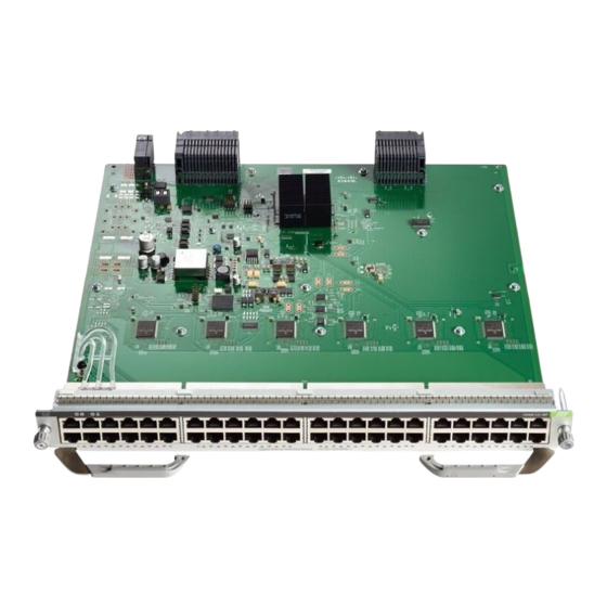
- Page 15 Cisco Catalyst 9400 Series 48-Port Gigabit Ethernet POE/POE+ Module (C9400-LC-48P) Description 48-port, 10/100/1000 BASE-T Gigabit Ethernet switching module supporting up to 30W per port on each of its 48 ports . • Hardware ready for IEEE 1588/802.1as— A Precision Time Protocol (PTP) used for time synchronization across the network for video and audio applications.
- Page 16 Figure 6: Front View of the C9400-LC-48P Switching Module STATUS LED Switching module Radio Frequency Identifier (RFID) LOCATE (blue beacon) LED Captive installation screws PORT LINK LED for the port in the top row Ejector levers PORT LINK LED for the port in the bottom row Model or product number...
- Page 17 • Hardware ready for IEEE 1588/802.1as— A Precision Time Protocol (PTP) used for time synchronization across the network for video and audio applications. • Supports Cisco Phone Discovery and IEEE 802.3af, IEEE 802.3at, and IEEE 802.3bt. • Supports Energy Efficient Ethernet (EEE) •...
- Page 18 PoE configuration. • Some legacy Cisco powered devices (like 7910, 7940, 7960 IP phones and AP350 wireless access points) are incompatible with Type 4 Power Supply Equipments (PSEs), as defined in the IEEE 802.3bt standard.
- Page 19 Figure 7: Front View of the C9400-LC-48H Switching Module STATUS LED Switching module Radio Frequency Identifier (RFID) LOCATE (blue beacon) LED Captive installation screws PORT LINK LED for the port in the top row Ejector levers PORT LINK LED for the port in the bottom row Model or product number...
- Page 20 Ten Gigabit Ethernet Switching Modules Cisco Catalyst 9400 Series 24-Port SFP/SFP+ Module (C9400-LC-24XS) 24 Port SFP/SFP+ 10 Gigabit Ethernet Module. These ports can be interchangeably used as 1G Description and 10G ports. • Hardware ready for IEEE 1588/802.1as— A Precision Time Protocol (PTP) used for time synchronization across the network for video and audio applications.
- Page 21 Figure 8: Front View of the C9400-LC-24XS Switching Module STATUS LED Captive installation screws LOCATE (blue beacon) LED Ejector levers PORT LINK LED for the port in the top row Model or product number Switching module Radio Frequency Identifier (RFID)
-
Page 22: Cisco Catalyst 9400 Series Switching Module Leds
Removing and Replacing Switching Modules All Cisco Catalyst 9400 Series Modules support hot swapping, which lets you install, remove, replace, and rearrange switching modules without powering off the system. When the system detects that a switching module has been installed or removed, it runs diagnostic and discovery routines automatically, acknowledges the presence or absence of the module, and resumes the system operation with no operator intervention. -
Page 23: Required Tools
Warning Ultimate disposal of this product should be handled according to all national laws and regulations. Statement 1040 Identifying Switching Module Slots The slot numbers on the fan tray front panel help you easily identify the switching module slots or the non-supervisor slots. Install switching modules only in these slots. - Page 24 Removing the Switching Module Warning Hazardous voltage or energy is present on the backplane when the system is operating. Use caution when servicing. Statement 1034 Warning Invisible laser radiation may be emitted from disconnected fibers or connectors. Do not stare into beams or view directly with optical instruments.
- Page 25 Captive installation screws that must be loosened Ejector levers that must be pivoted out Step 5 Grasp the module front panel with one hand, and place your other hand under the module (on the metal carrier) to support and guide it out of the slot. Do not touch the printed circuit boards or connector pins. Step 6 Pull the module straight out of the slot, keeping one hand under the module to support it.
- Page 26 Warning Invisible laser radiation may be emitted from disconnected fibers or connectors. Do not stare into beams or view directly with optical instruments. Statement 1051 Caution To prevent electrostatic discharge (ESD) damage, handle modules by the carrier edges only. Procedure Step 1 Take the necessary precautions to prevent ESD damage.
- Page 27 Install any necessary transceivers in the module ports. Installation instructions along with safety warnings for the various types of transceivers can be found at the following URL: https://www.cisco.com/en/US/products/hw/modules/ps5455/prod_installation_guides_list.html Step 12 Attach any necessary network interface cables or other devices to the interface ports.
-
Page 28: Related Documentation
• Regulatory Compliance & Safety Information Document: https://www.cisco.com/c/dam/en/us/td/docs/switches/lan/catalyst9400/ hardware/regulatory/RCSI-0315-book.pdf Consolidated list of safety warnings relevant to Catalyst 9400 Series Switches (all chassis models), supervisor modules, line cards and any other hardware components. Software Documentation • Software Configuration Guide: https://www.cisco.com/c/en/us/support/switches/catalyst-9400-series-switches/... - Page 29 Provides detailed software configuration information for the features supported on the switch. These guides are release-specific. • Command Reference: https://www.cisco.com/c/en/us/support/switches/catalyst-9400-series-switches/ products-command-reference-list.html Provides command syntax, command history and usage guidelines for the Cisco IOS commands supported on the switch. These guides are release-specific.
-
Page 30: Notices
REFERENCE. IF YOU ARE UNABLE TO LOCATE THE SOFTWARE LICENSE OR LIMITED WARRANTY, CONTACT YOUR CISCO REPRESENTATIVE FOR A COPY. The Cisco implementation of TCP header compression is an adaptation of a program developed by the University of California, ©... - Page 31 © 2017 Cisco Systems, Inc. All rights reserved.
- Page 32 Americas Headquarters Asia Pacific Headquarters Europe Headquarters Cisco Systems, Inc. CiscoSystems(USA)Pte.Ltd. CiscoSystemsInternationalBV San Jose, CA 95134-1706 Singapore Amsterdam,TheNetherlands Cisco has more than 200 offices worldwide. Addresses, phone numbers, and fax numbers are listed on the Cisco Website at www.cisco.com/go/offices.
Need help?
Do you have a question about the Catalyst 9400 Series and is the answer not in the manual?
Questions and answers