
Related Manuals for Eaton DCM2000-A21X


Summary of Contents for Eaton DCM2000-A21X
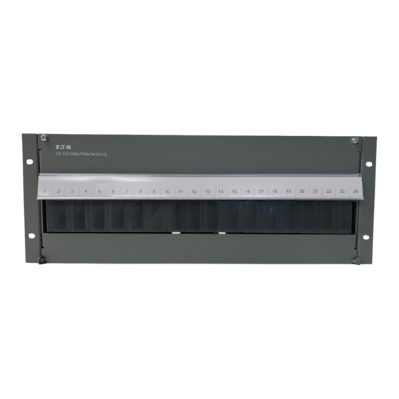
- Page 1 DCM2000-A21X DC DISTRIBUTION MODULE Installation and Operation Guide Issue: IEE1157-007-03 Issue Date: February 2012 Eaton Corporation Telecommunications Power Solutions www.eaton.com/telecompower DCinfo@eaton.com...
- Page 2 Copyright © 2011 Eaton Industries Pty Ltd All Rights Reserved Document IEE1157-007-03...
- Page 3 About This Guide Purpose This guide provides instructions to correctly configure and install the Eaton DCM2000-A21X Distribution Module. Audience This guide is intended for use by; Installers competent in: o installing and commissioning dc power systems o safe working practices for ac and dc powered equipment o the relevant local electrical safety regulations and wiring standards ...
-
Page 4: Table Of Contents
DCM200-21X Specifications Selection of Circuit Breakers Chapter 5 – Installation Details Typical DCM2000 Distribution Module Installation Procedure Removing insulators Appendix – Drawings and Information Copyright © 2011 Eaton Industries Pty Ltd All Rights Reserved Document IEE1157-007-03... -
Page 5: Chapter 1 - Warnings
Short circuit currents of several thousand amps can occur. As a general rule, use insulated tools and do not wear rings, watches and jewelery. Copyright © 2011 Eaton Industries Pty Ltd All Rights Reserved... -
Page 6: Chapter 2 - General Description
Outgoing common cabling from rear common bar, single screw , 2P bar or 3P bar (remove front panel and blank panel above for access).- M6 (¼”) threads Copyright © 2011 Eaton Industries Pty Ltd All Rights Reserved Document IEE1157-007-03... - Page 7 2 pole or 3 pole paralleling busbar. Paralleling busbars and insulators are shown below. Circuit breaker kits for double pole or triple pole breakers can be supplied by Eaton Each kit contains the actual circuit breaker, the associated paralleling busbar and the associated insulator Copyright ©...
-
Page 8: Circuit Breaker Plug-In Positions
The breaker plugs into the lower two brass cylinders above and below the auxiliary contact connection printed circuit board. Picture below shows breaker plug-in power and auxiliary contact connections. Copyright © 2011 Eaton Industries Pty Ltd All Rights Reserved Document IEE1157-007-03... -
Page 9: Rear Connections - Incoming Live & Common
Rear Live A and B negative incoming M10 bolt connections shown in the lower area below Important Note Incoming cable connections should be spread across busbar connections to achieve optimum busbar current rating Copyright © 2011 Eaton Industries Pty Ltd All Rights Reserved Document IEE1157-007-03... -
Page 10: Dcm Chassis Earth Connection
An M10 clearance hole is provided in the rear area of the side panel for connecting the chassis earth cable, as shown below. Circuit Breaker Options The plug-in circuit breaker positions accept Eaton Heinemann Hydraulic-Magnetic breakers type AM/R and AM1P with the following ranges:- ... -
Page 11: Auxiliary Alarm Contact Details
1 to pin 6 of the RJ45 connector. For this to occur, the header link should be between pins 2 and 3. The pcb identifies pin 3.and the link should be in the right hand position. Copyright © 2011 Eaton Industries Pty Ltd All Rights Reserved Document IEE1157-007-03... - Page 12 This shows a diode in series with the common alarm output, indicating that this circuit will pull down on a high digital input to give an alarm. Copyright © 2011 Eaton Industries Pty Ltd All Rights Reserved...
-
Page 13: Eaton Heinemann Catalogue
Chapter 3 Circuit Breaker Details Eaton Heinemann Catalogue Refer to the Eaton Heinemann catalogue for Heinemann AM/R and AM1 P breaker details. Selected Circuit Breaker Options The following breaker kits and separate breakers have been selected as preferred options. Each breaker kit includes the breaker, 2 x paralleling busbars and insulator... - Page 14 27401012 breaker 61240014 Insulator for 3P Eaton Heinemann 27401013 breaker 61240009 System, Telstra LOD Rack, 2 LODS fitted 27401014 61240011 System, Telstra LOD Rack, 4 LODS fitted 27401015 Copyright © 2011 Eaton Industries Pty Ltd All Rights Reserved Document IEE1157-007-03...
-
Page 15: Chapter 4 - Specifications And Selection Of Breakers
These selection guide rules include the following:- These Eaton Heinemann breakers are magnetic / hydraulic and not sensitive to ambient temperature variation. There is no requirement to apply temperature de-rating as for thermal breakers. - Page 16 10 breaker positions. For loads with high inrush current it may be necessary to check the breaker sizing. The following diagram shows the Time Delay DC Curve 3 characteristic of the Eaton Heinemann breakers supplied.
-
Page 17: Chapter 5 - Installation Details
Step 2 – Access circuit breakers Open the hinged front cover. Undo and remove the circuit breaker cover To remove any breakers already fitted, pull out. Copyright © 2011 Eaton Industries Pty Ltd All Rights Reserved Document IEE1157-007-03... - Page 18 Terminate the load cables (live and common) with double hole crimp lugs. Hole details and hole centre dimensions are shown in the table below. Fit heatshrink to exposed crimp connections on lugs (blue for live and red for common). Copyright © 2011 Eaton Industries Pty Ltd All Rights Reserved Document IEE1157-007-03...
- Page 19 Refer to the equipment manufacturer’s instructions before applying dc power to any equipment To apply dc power to the equipment, switch on the circuit breaker Close the hinged front cover. Copyright © 2011 Eaton Industries Pty Ltd All Rights Reserved Document IEE1157-007-03...
-
Page 20: Removing Insulators
To remove an insulator remove the single countersunk screw above the crimp lug fixing studs Remove screw and insulator lifts out vertically. Screwdriver removing insulator fixing screw Copyright © 2011 Eaton Industries Pty Ltd All Rights Reserved Document IEE1157-007-03... -
Page 21: Appendix - Drawings And Information
Appendix Drawings and Information Copyright © 2011 Eaton Industries Pty Ltd All Rights Reserved Document IEE1157-007-03... - Page 22 UPDATED WITH NEW MCB CONNECTOR REF-E35339 9.4.08 CORPORATION, AND IS MERELY ON LOAN AND SUBJECT TO RECALL BY EATON AT ANY TIME. BY TAKING POSSESSION OF THIS DOCUMENT, THE LOAD ALARM BOARD RECIPIENT ACKNOWLEDGES AND AGREES THAT THIS DOCUMENT CANNOT BE USED IN ANY MANNER ADVERSE TO THE INTERESTS OF EATON AND 3700166 P68 NOW NON-FITTED, R1 WAS 0.1% PART REF-E36657...
- Page 23 Please enter as much information as you can. Send the completed form, together with the item for repair to your nearest authorized service agent. NOTE: Only one fault to be recorded per form. For further information contact your local Eaton dc product supplier or Eaton (see contact details on page 95). Or email: CustomerServiceNZ@eaton.com...
- Page 24 INFORMATION continued (fault details, circumstances, consequences, actions) SG/03 ISS06 Copyright © 2008-2009 Eaton Corporation. All Rights Reserved.
- Page 25 Worldwide Support Worldwide Support For product information and a complete listing of worldwide sales offices, visit Eaton's website at: www.eaton.com/telecompower or email: DCinfo@eaton.com For technical support contact either your local Eaton dc product representative, the closest office from the following list, telephone (+64) 3 343-7448, or email CustomerServiceNZ@eaton.com...
Need help?
Do you have a question about the DCM2000-A21X and is the answer not in the manual?
Questions and answers