Advertisement
Table of Contents
Advertisement
Table of Contents

Related Manuals for Risco RW132KPPW3


Summary of Contents for Risco RW132KPPW3
- Page 1 Wireless Keypad Model: RW132KPPW3...
-
Page 3: Table Of Contents
Table of Contents INTROUCTION ........................4 MAIN FEATURES ......................4 COMMUNICATION SETUP .................... 4 MOUNTING THE KEYPAD ..................... 5 MAIN USER OPERATIONS ..................... 6 COMMON OPERATIONS ....................6 KEY OPERATION DURING PROGRAMMING MODE ..........6 ADVANCED OPERATIONS ..................7 LEDS INDICATION ......................8 SLEEP MODE ........................8 REPLACING BATTERIES ....................8 CHANGING KEYPAD PARAMETERS ................. 9 TECHNICAL SPECIFICATIONS .................. -
Page 4: Introuction
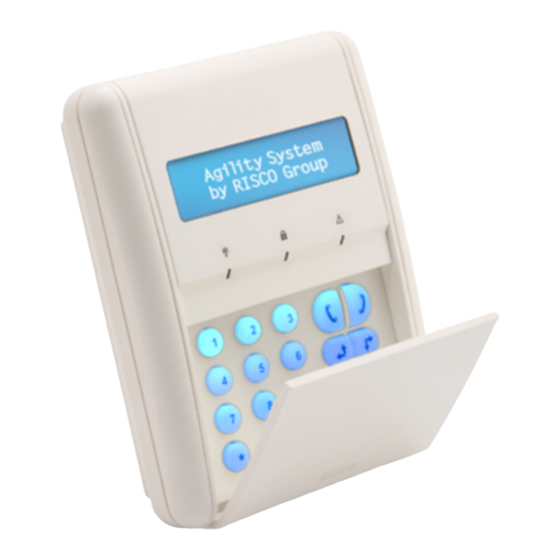
INTRODUCTION The Wirless keypad is used to remotely program and operate the WiComm Smart Hub. Being bi‐directional the keypad receives a reply status indication from the panel for each command that it has sent to the Smart Hub. To use functions of the keypad you can use a code or a proximity tag. COMMUNICATION SETUP The keypad must identify itself to the WiComm Smart Hub. This can be performed either using the RISCO Express Wizard (www.riscocloud.com/express) by adding the keypad at the same time of the Smart Hub system installation or later either by using the “Settings” on the Web (www.riscocloud.com) or using the WiComm Smart Hub, as follows: Press the button on the WiComm Smart Hub for 5 seconds; the unit beeps once as it enters Learn mode (all the LEDs also light up, one after the other). Remove the red isolation strips to activate the batteries. Send a signal transmission from the keypad by pressing and simultaneously for at least 2 seconds; the Smart Hub beeps once to accept or beeps three times to reject. Once accepted, the system announces the device type and its zone (for example, “Keypad, zone 1”). To complete allocation, momentarily press the WiComm Smart Hub button . A short beep is heard and the LEDs stop flashing. Note: For future use, it is recommended to write down the keypad description and its location. ... -
Page 5: Mounting The Keypad
MOUNTING THE KEYPAD Mount the keypad on the wall using the supplied mounting bracket. Note: Before mounting the keypad test the keypad communication with the system. 1. Release the Mounting bracket screw (1). Figure 1 2. Slide up the Main Unit (3) to release it from the two mounting bracketʹs locking tabs (2). 3. Mount the bracket. Figure 2 4. Release the battery cover screw (1) and remove the red isolation strips. (The keypad is supplied with 3 batteries.) 5. Close the battery compartment and mount the keypad to the mounting bracket in a reverse sequence to the removal. Figure 3 ... -
Page 6: Main User Operations
MAIN USER OPERATIONS The following list details the user operations from the wireless keypad. User operation can be defined to be activated by a quick mode or high security mode that requires the use of a code or proximity tag. In the high security mode the proximity tag can be used as a substitute for inserting a user code when the display prompts to ʺInsert a codeʺ. COMMON OPERATIONS Operation Quick Operation Away arming Press Stay (Home) Press Arming Disarm Press followed by code or proximity tag For Stay Arming with no entry delay press the key for two seconds. For optimal use of the proximity tag, use it from a distance of 1‐2 cm from the center of the keypadʹs door. KEY OPERATION DURING PROGRAMMING MODE Key Description Numerical keys are used to input the numeric codes that may be required for setting, unsetting, or used to activate specific functions Exits from the current menu and returns to Normal Operation mode ... -
Page 7: Advanced Operations
ADVANCED OPERATIONS Quick Operation Operation Away Arming Select partition and press partition 1/2/3 Stay Arming Select partition and press partition 1/2/3 Disarming partition 1/2/3 Select partition and press followed by the code or the proximity tag Panic alarm / Press both keys simultaneously. If programmed. Service call Fire Alarm Press simultaneously for 2 seconds. If programmed. Emergency / Press simultaneously for 2 seconds. If programmed. Medical Alarm System Chime Press the button for 2 seconds On/Off ... -
Page 8: Leds Indication
Quick Operation Operation Enter Press and enter the code programming mode Changing Keypad Press simultaneously for 2 seconds. Select the Language language and press to confirm. 1 All operations are available while keypad is turned on (Not in Sleep Mode) 2 If defined by your installer. LEDS INDICATION Key Function Communication with the panel (Blue) On: System is armed in Away or Stay (Home) Slow flash: Exit delay (Red) Rapid flash: Alarm Trouble in the system while the system is disarmed (Yellow) SLEEP MODE For extending the battery life of the keypad, the keypad is designed with a Sleep mode function. By default, 10 seconds after the last key has been pressed, the keypad will turn off its display and LEDs. The time can be configured by your installer to a maximum of 60 seconds. REPLACING BATTERIES (see Figure 3) 1. -
Page 9: Changing Keypad Parameters
CHANGING KEYPAD PARAMETERS Any change performed in the definition of the keypad parameters requires to update the keypad as well. This is performed by pressing the key for 2 seconds. Doing so, the panel will send an update to the keypad. Note: Perform this function after exiting Programming mode to ensure that any changes made are synchronized between the WiComm Smart Hub and the LCD Keypad. TECHNICAL SPECIFICATIONS Electrical Battery Type CR123, 3V lithium battery (x3) Current Consumption Standby current 10μA, Max current 100 mA Frequency 915 MHz Typical Battery Life 3 years Physical Dimension (HxWxD) 150 mm x 120 mm x 45 mm (5.9 x 4.7 x 1.77 inches) Weight (Including batteries) 0.395 kg Environmental Operating temperature ‐10°C to 40°C (14°F to 104°F) Storage temperature ‐20°C to 70°C (‐4°F to 158°F) ... - Page 10 FCC ID: JE4RW132KPP1356 Contains FCC ID: JE4STAMP915 This device complies with part 15 of the FCC Rules. Operation is subject to the following two conditions: (1) This device may not cause harmful interference, and (2) This device must accept any interference received, including interference that may cause undesired operation. Any Changes or modifications not expressly approved by the party responsible for compliance could void the userʹs authority to operate the equipment FCC Note This equipment has been tested and found to comply with the limits for a Class B digital device, pursuant to part 15 of the FCC Rules. These limits are designed to provide reasonable protection against harmful interference in a residential installation. This equipment generates uses and can radiate radio frequency energy and, if not installed and used in accordance with the instructions, may cause harmful interference to radio communications. However, there is no guarantee that interference will not occur in a particular installation. If this equipment does cause harmful interference to radio or television reception, which can be determined by turning the equipment on and off, the user is encouraged to try to correct the interference by one or more of the following measures: Reorient or relocate the receiving antenna. Increase the separation between the equipment and the receiver. Connect the equipment into an outlet on to a different circuit from that to which the receiver is connected. Consult the dealer or an experienced radio/TV technician for help. This RISCO product was purchased from: No part of this document may be reproduced in any form without prior written permission from the publisher. ...
-
Page 11: Standard Limited Product Warranty
Standard Limited Product Warranty (“Limited Warranty”) RISCO Ltd. (“RISCOʺ) guarantee RISCO’s hardware products (“Products”) to be free from defects in materials and workmanship when used and stored under normal conditions and in accordance with the instructions for use supplied by RISCO, for a period of (i) 24 months from the date of delivery of the Product (the “Warranty Period”). This Limited Warranty covers the Product only within the country where the Product was originally purchased and only covers Products purchased as new. Contact with customers only. This Limited Warranty is solely for the benefit of customers who ... - Page 12 Product. Manufacturers, suppliers, or third parties other than RISCO may provide their own warranties, but RISCO, to the extent permitted by law and except as otherwise specifically set forth herein, provides its Products “AS IS”. Software and applications distributed or made available by RISCO in conjunction with the Product (with or without the RISCO brand), including, but not limited to system software, as well as P2P services or any other service made available by RISCO in relation to the Product, are not covered under this Limited Warranty. Refer to the Terms of Service at: https://riscocloud.com/ELAS/WebUI/UserLogin/License for details of your rights and ...
Need help?
Do you have a question about the RW132KPPW3 and is the answer not in the manual?
Questions and answers