Juniper QFX5120 Series Quick Start Manual
Hide thumbs
Also See for QFX5120 Series:
- Hardware manual (321 pages) ,
- Quick start manual (17 pages) ,
- Manual (15 pages)
Table of Contents
Advertisement
Quick Start Guide
QFX5120 Switch Quick Start
IN THIS GUIDE
System Overview | 1
System Overview
The Juniper Networks
and 100-Gigabit Ethernet (100GbE) uplinks, making it the ideal switch for access and top-of-rack deployments and for
enterprise multicloud deployments. Featuring Layer 3 gateway capabilities for routing between virtualized and bare-metal
servers, the QFX5120 is designed for extremely agile data centers that demand support for overlay and underlay network
architectures.
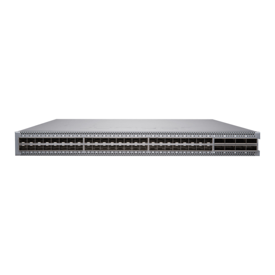
The QFX5120 switches are available in three models-QFX5120-32C, QFX5120-48Y, and QFX5120-48T. Each model is
available in two variants featuring AC power supplies with front-to-back or back-to-front airflow and two variants featuring
DC power supplies with front-to-back or back-to-front airflow.
QFX5120-32C switches offer 32 100GbE ports that support quad small form-factor pluggable 28 (QSFP28) transceivers
and 2 10GbE ports that support small form-factor pluggable plus (SFP+) transceivers. Junos OS Release 19.1R1 is the first
Junos OS release that supports QFX5120-32C switches.
®
QFX5120 Switch delivers low-latency, rich Layer 2 and Layer 3 features, VXLAN overlay support,
Advertisement
Table of Contents

Related Manuals for Juniper QFX5120 Series


Summary of Contents for Juniper QFX5120 Series
-
Page 1: Table Of Contents
Step 3: Connect the QFX5120 Switch to Earth Ground | 9 Step 4: Connect Power to the Switch | 10 Step 5: Perform Initial Configuration | 16 Safety Warnings Summary | 19 Contacting Juniper Networks | 20 System Overview ® The Juniper Networks... -
Page 2: Tools And Parts Required For Installation
Junos OS release that supports QFX5120-48T switches. You can channelize the QSFP28 ports and connect breakout cables. NOTE: See the complete documentation at https://www.juniper.net/documentation/product/en_US/qfx5120. Tools and Parts Required for Installation Ensure that you have the following parts and tools available: Number 2 Phillips (+) screwdriver—not provided... -
Page 3: Step 1: Unpack The Qfx5120 Switch
Register product serial numbers on the Juniper Networks website and update the installation base data if there is any addition or change to the installation base or if the installation base is moved. Juniper Networks will not be held accountable for not meeting the hardware replacement service-level agreement for products that do not have registered serial numbers or accurate installation base data. -
Page 4: Step 2: Mount The Switch On Four Posts Of A Rack
CAUTION: QFX5120 switches are maximally protected inside the shipping carton. Do not unpack the switches until you are ready to begin installation. To unpack the switch: 1. Move the shipping carton to a staging area as close to the installation site as possible, but where you have enough room to remove the system components. - Page 5 Read General Safety Guidelines and Warnings. Ensure that you have taken the necessary precautions to prevent electrostatic discharge (ESD) damage (see Prevention of Electrostatic Discharge Damage). NOTE: One person must be available to lift the switch while another person secures the switch to the rack. CAUTION: If you are mounting multiple units on a rack, mount the heaviest unit at the bottom of the rack, and then mount the other units from the bottom of the rack to the top in decreasing order of...
- Page 6 If you are mounting a QFX5120-48Y or QFX5120-48T switch flush with the front posts of a rack: a. Align the front mounting bracket assembly (provided with the rack mount kit) along the side panel of the switch such that the front of the bracket is flush with the front panel of the switch chassis. b.
- Page 7 Figure 4: Secure the QFX5120-32C Switch to the Front Posts of a Rack to Mount the Switch Flush with the Front Posts of a Rack Figure 5: Secure the QFX5120-48Y Switch to the Front Posts of a Rack to Mount the Switch Flush with the Front Posts of a Rack Figure 6: Secure the QFX5120-48T Switch to the Front Posts of a Rack to Mount the Switch Flush with the Front Posts of a Rack...
- Page 8 Figure 7: Secure the QFX5120-32C Switch to the Rear Post of the Rack by Using the Rear Mounting Brackets c. Secure the rear mounting brackets to the side mounting rails by using the pan head M4X8 screws provided. Tighten the screws. If you are mounting a QFX5120-48Y or QFX5120-48T switch: a.
-
Page 9: Step 3: Connect The Qfx5120 Switch To Earth Ground
NOTE: We recommend that you install covers in all unused power supply slots. Step 3: Connect the QFX5120 Switch to Earth Ground To ensure proper operation and to meet safety and electromagnetic interference (EMI) requirements, you must connect the switch to earth ground before you connect power to the switch. You must use the protective earthing terminal on the switch chassis to connect the switch to ground. -
Page 10: Step 4: Connect Power To The Switch
Figure 10: Connect a Grounding Cable to a QFX5120-32C Switch Figure 11: Connect a Grounding Cable to a QFX5120-48Y or QFX5120-48T Switch 3. Secure the grounding lug to the protective earthing terminal with the washers and screws. 4. Dress the grounding cable and ensure that it does not touch or block access to other switch components. WARNING: Ensure that the cable does not drape where people could trip over it. - Page 11 Before you begin connecting AC power to the switch: Ensure that you have a power cord appropriate for your geographical location available. Ensure that you have taken the necessary precautions to prevent electrostatic discharge (ESD) damage (see Prevention of Electrostatic Discharge Damage). Ensure that you have connected the switch chassis to earth ground.
- Page 12 Figure 12: Connect Power to an AC-Powered QFX5120-32C Switch Figure 13: Connect Power to an AC-Powered QFX5120-48Y or QFX5120-48T Switch 6. If the AC power source outlet has a power switch, set it to the off position. NOTE: The switch powers on as soon as power is provided to the power supply. There is no power switch on the QFX5120.
- Page 13 To connect power to a DC-powered QFX5120-32C switch: 1. Wrap and fasten one end of the ESD wrist strap around your bare wrist, and connect the other end of the strap to a site ESD point. 2. Ensure that the input circuit breaker is open so that the voltage across the DC power source cable leads is 0 V and that the cable leads do not become active while you are connecting DC power.
- Page 14 NOTE: The switch powers on as soon as power is provided to the power supply. There is no power switch on the QFX5120. To DC power to a DC-powered QFX5120-48Y or QFX5120-48T switch: 1. Wrap and fasten one end of the ESD wrist strap around your bare wrist, and connect the other end of the strap to a site ESD point.
- Page 15 WARNING: Ensure that the power cables do not block access to device components or drape where people can trip on them. 7. Connect each power supply to the power sources. Secure power source cables to the power supplies by screwing the ring lugs attached to the cables to the appropriate terminals by using the screw from the terminals (see Figure 15).
-
Page 16: Step 5: Perform Initial Configuration
Figure 15: Secure Ring Lugs to the Terminals on the QFX51200-48Y or QFX51200-48T DC Power Supply 8. Replace the terminal block cover. 9. Close the input circuit breaker. NOTE: The switch powers on as soon as power is provided to the power supply. There is no power switch on the QFX5120. - Page 17 3. Set the following values by using the console server or PC: Baud rate—9600 Flow control—none Data—8 Parity—none Stop bits—1 DCD state—disregard 4. Connect the console port (labeled CON) on the rear panel of the switch to a laptop or PC by using the RJ-45 to DB-9 serial port adapter.
- Page 18 11. Configure the IP address and prefix length for the switch management interface. [edit] root@# set interfaces em0 unit 0 family inet address address/prefix-length NOTE: The management port em0 (labeled MGMT) is located on the front panel of the QFX5120-32C switch.
-
Page 19: Safety Warnings Summary
You can now log in by using the CLI and continue configuring the switch. Safety Warnings Summary This is a summary of safety warnings. For a complete list of warnings, including translations, see the QFX5120 documentation at https://www.juniper.net/documentation/product/en_US/qfx5120. WARNING: Failure to observe these safety warnings can result in personal injury or death. -
Page 20: Contacting Juniper Networks
For technical support, see http://www.juniper.net/support/requesting-support.html. Juniper Networks, the Juniper Networks logo, Juniper, and Junos are registered trademarks of Juniper Networks, Inc. in the United States and other countries. All other trademarks, service marks, registered marks, or registered service marks are the property of their respective owners.
Need help?
Do you have a question about the QFX5120 Series and is the answer not in the manual?
Questions and answers