
Related Manuals for Siemens RVD240


Summary of Contents for Siemens RVD240
- Page 1 RVD240 District Heating and Domestic Hot Water Controller Basic Documentation Edition 3.0 Controller series D Siemens Building Technologies CE1P2384en HVAC Products 27.05.2004...
- Page 2 Siemens Building Technologies AG © 1999 Siemens Building Technologies AG HVAC Products Subject to change Gubelstrasse 22 CH 6301 Zug Tel. +41 41 724 24 24 Fax +41 41 724 35 22 www.landisstaefa.com 2/126 Siemens Building Technologies Basic documentation RVD240...
-
Page 3: Table Of Contents
Room temperature (A6)................. 25 4.4.1 Types of sensors ................... 25 4.4.2 Handling faults....................25 4.4.3 Room model ....................25 D.h.w. temperature (B3) ................25 4.5.1 Measured variable ..................25 3/126 Siemens Building Technologies Basic documentation RVD240 CE1P2384en HVAC Products Contents 27.05.2004... - Page 4 10.2 Indication of errors ..................34 Function block Plant configuration ..............35 11.1 Operating lines....................35 11.2 Parameters to be set..................35 11.2.1 Plant type .......................35 11.2.2 Input B71 / U1 ....................35 4/126 Siemens Building Technologies Basic documentation RVD240 CE1P2384en HVAC Products Contents 27.05.2004...
- Page 5 Mode of operation with room sensor ............. 51 12.10.3 Mode of operation without room sensor ............51 12.11 Protective functions ..................52 12.11.1 Pump kick ...................... 52 12.11.2 Valve kick ...................... 52 5/126 Siemens Building Technologies Basic documentation RVD240 CE1P2384en HVAC Products Contents 27.05.2004...
- Page 6 D.h.w. heating with storage tanks ..............63 16.1.1 General ......................63 16.1.2 Maximum charging time.................63 16.1.3 Manual storage tank heating................63 16.1.4 Forced charging .....................63 16.1.5 Protection against discharging...............64 16.1.6 Protection against overtemperatures .............64 6/126 Siemens Building Technologies Basic documentation RVD240 CE1P2384en HVAC Products Contents 27.05.2004...
- Page 7 Function block Assignment of d.h.w.............. 75 19.1 Operating line ....................75 19.2 Assignment of d.h.w. heating ................ 75 Function block LPB parameters ..............76 20.1 Operating lines ....................76 20.2 LPB parameters..................... 76 7/126 Siemens Building Technologies Basic documentation RVD240 CE1P2384en HVAC Products Contents 27.05.2004...
- Page 8 Function block PPS parameter ..............86 24.1 Operating lines....................86 24.2 Suitable devices.....................86 24.3 Impacts of a room unit on the heating circuits ..........86 Function block Test and display..............87 25.1 Operating lines....................87 8/126 Siemens Building Technologies Basic documentation RVD240 CE1P2384en HVAC Products Contents 27.05.2004...
- Page 9 General......................100 29.3.2 Overriding the operating mode ..............101 29.3.3 Knob for readjusting the room temperature..........101 29.3.4 Impact of the individual QAW70 operating lines on the RVD240 ....101 9/126 Siemens Building Technologies Basic documentation RVD240 CE1P2384en HVAC Products Contents 27.05.2004...
- Page 10 Lightning protection in M-bus plants ............110 32.5 Connection diagrams ...................111 32.5.1 Low-voltage side ..................111 32.5.2 Mains voltage side ..................111 Mechanical design ..................112 33.1 Basic design....................112 33.2 Dimensions ....................112 Technical data....................113 10/126 Siemens Building Technologies Basic documentation RVD240 CE1P2384en HVAC Products Contents 27.05.2004...
- Page 11 D.h.w. heating Term Explanation Coil type storage tank Instantaneous d.h.w. heating (via heat exchanger) Stratification storage tank Storage tanks Common term used for coil type and stratification storage tanks. 11/126 Siemens Building Technologies Basic documentation RVD240 CE1P2384en HVAC Products Glossary 27.05.2004...
- Page 12 12/126 Siemens Building Technologies Basic documentation RVD240 CE1P2384en HVAC Products Glossary 27.05.2004...
-
Page 13: Summary
Only room-compensated control of the heating circuit flow temperatures − Demand-dependent control of the common heating circuit flow temperature − • In terms of d.h.w. control, the RVD240 is designed for the following types of applica- tions: D.h.w. heating with coil type storage tanks −... -
Page 14: Suitable Room Units
• Room unit QAW70 1.3.3 Suitable valve actuators All actuators from Siemens with the following features can be used: • Electric or electrohydraulic actuators with a running time of 10...900 seconds • 3-position control • Operating voltage AC 24 V...AC 230 V 1.3.4... -
Page 15: Use
Types of plant Basically, the RVD240 is suited for the control of all types of heating plants in houses or buildings • that are connected to a district heat network • that use 2 heating circuits • in which the flow temperature of the heating circuits is controlled either weather- or room-compensated •... -
Page 16: Functions
• Remote operation via room unit D.h.w. functions The RVD240 is used if one or several of the following d.h.w. functions is / are required: • Common or separate heat exchangers for the heating circuit and for d.h.w. heating • D.h.w. heating with a coil type storage tank, with charging pump •... - Page 17 • Relay test • Display of setpoint • Display of all active limitations • Locking of settings • Connection of sensors for display only 17/126 Siemens Building Technologies Basic documentation RVD240 CE1P2384en HVAC Products 2 Use 27.05.2004...
-
Page 18: Fundamentals
3.1.2 Plant types The RVD240 has 14 plant types preprogrammed; the functions required for each type of plant are ready assigned. When commissioning the installation, the relevant plant type must be selected. Each plant type is comprised of 2 heating circuits and 1 d.h.w. circuit. When making use of all possible or practical combinations, the above mentioned total of 14 plant types are available. - Page 19 Storage tank charging pump 2-port valve primary return heating circuit 2 2-port valve d.h.w. primary return 2-port valve primary return heating circuit 2 Suppression of hydraulic creep 19/126 Siemens Building Technologies Basic documentation RVD240 CE1P2384en HVAC Products 3 Fundamentals 27.05.2004...
- Page 20 Mixing valve heating circuit 2 a) Circulating pump feeding water into the heat exchanger’s return Suppression of hydraulic creep b) Circulating pump feeding water into the storage tank 20/126 Siemens Building Technologies Basic documentation RVD240 CE1P2384en HVAC Products 3 Fundamentals 27.05.2004...
- Page 21 Pump heating circuit 2 Circulating pump (optional) 2-port valve common heating circuit flow 2-port valve d.h.w. primary return Mixing valve heating circuit 2 Suppression of hydraulic creep 21/126 Siemens Building Technologies Basic documentation RVD240 CE1P2384en HVAC Products 3 Fundamentals 27.05.2004...
-
Page 22: Operating Modes
Circulating pump feeding water into the storage tank Operating modes 3.2.1 Heating circuit control The RVD240 offers the following operating modes: Automatic operation • Automatic heating operation, changeover between the nominal room temperature and the reduced room temperature according to the time program •... -
Page 23: Heating
• All pumps are in operation • The 2-port valve in the primary circuit can be manually adjusted with set- ting buttons For more detailed information, refer to chapter 30 "Manual operation". 23/126 Siemens Building Technologies Basic documentation RVD240 CE1P2384en HVAC Products 3 Fundamentals 27.05.2004... -
Page 24: Acquisition Of Measured Values
But this will not cause any damage. In the case of severe faults, which do not allow the RVD240 to perform its control func- tions, an error message will be generated. The controller displays this as Er (Error). -
Page 25: Room Temperature (A6)
4.4.3 Room model The RVD240 uses a room model for each heating circuit that is ready integrated in the controller. It simulates the room temperature based on the progression of the outside temperature and the type of building construction, using a defined attenuation. In plants with no room temperature measurement, the room model ensures optimum start con- trol. -
Page 26: Handling Faults
4.7.2 Types of sensors The type of sensor is the QAE22... immersion sensor with a sensing element LG- Ni 1000. Thermostats cannot be used. 26/126 Siemens Building Technologies Basic documentation RVD240 CE1P2384en HVAC Products 4 Acquisition of measured values 27.05.2004... -
Page 27: Handling Faults
In that case, the controller’s LCD shows Er. 27/126 Siemens Building Technologies Basic documentation RVD240 CE1P2384en HVAC Products 4 Acquisition of measured values 27.05.2004... -
Page 28: Function Block Space Heating
At the same time, this setting represents the setpoint for the holiday mode. A holiday program can be entered either on the controller or on the QAW70 room unit. For 28/126 Siemens Building Technologies Basic documentation RVD240 CE1P2384en HVAC Products 5 Function block Space heating... -
Page 29: Heating Program
Heating program The heating program of the RVD240 provides a maximum of 3 heating periods per day; also, every weekday can have different heating periods. Every heating period is defined by a start and an end time. -
Page 30: Function Block Clock Settings
1995...2094 Entries The RVD240 has a yearly clock with the time of day, the weekday and the date. The changeover from summer- to wintertime, and vice versa, takes place automatically. Should the respective regulations change, the changeover dates can be adjusted (refer to operating lines 144 and 145). -
Page 31: Function Block End-User D.h.w
8…Normal setpoint D.h.w. heating program The d.h.w. heating program of the RVD240 provides a maximum of 3 release periods per day; also, every weekday can have different release periods. Every release period is defined by a start and an end. -
Page 32: Function Block Display Of Actual Sensor Values
The temperature displayed separately for each heating circuit is the temperature measured with the relevant sensor. If button is pressed, the controller will display the current setpoint 32/126 Siemens Building Technologies Basic documentation RVD240 CE1P2384en HVAC Products 8 Function block Display of actual sensor values 27.05.2004... -
Page 33: Function Block Holiday Settings
125 (assignment of d.h.w.), the holiday function will switch off d.h.w. heating and the circulating pump. The holiday program is only active in AUTO mode and applies to both heating circuits. 33/126 Siemens Building Technologies Basic documentation RVD240 CE1P2384en HVAC Products 9 Function block Holiday settings 27.05.2004... -
Page 34: Function Block Indication Of Errors
* If maximum limitation of the secondary return temperature is activated (by making an entry on operating line 177; lowering against the primary limit value), no error message will be delivered 34/126 Siemens Building Technologies Basic documentation RVD240 CE1P2384en HVAC Products 10 Function block Indication of errors... -
Page 35: Function Block Plant Configuration
• Setting 2: The RVD240 can receive DC 0...10 V signals from a plant element and then pass them on via M-bus. Plant element can be a differential pressure sensor, for instance. -
Page 36: Circulating Pump
(also refer to subsection 16.3.6 "Compensation of heat los- ses through control ". 11.2.4 Input H5 Terminal H5 of the RVD240 is a digital input. It offers the following choices (settings on operating line 55): 0 = No function 1 = reception of pulses with plant type 1–x, the mode of operation of the pulse input must be defined on... - Page 37 The heating output at operating point A is the same as the heating output that would result at operating point B (flow temperature according to the heating curve, minimum pump speed). 37/126 Siemens Building Technologies Basic documentation RVD240 CE1P2384en HVAC Products 11 Function block Plant configuration 27.05.2004...
- Page 38 The factory setting is 85 %. If the plant is correctly sized, this setting ensures a satisfac- tory performance and, for this reason, necessitates readjustments only in exceptional 38/126 Siemens Building Technologies Basic documentation RVD240 CE1P2384en HVAC Products 11 Function block Plant configuration...
- Page 39 The storage tank charging pump is controlled according to the d.h.w. flow temperature acquired with sensor B3; setpoint is the current d.h.w. temperature setpoint. 39/126 Siemens Building Technologies Basic documentation RVD240 CE1P2384en HVAC Products 11 Function block Plant configuration 27.05.2004...
-
Page 40: Function Block Space Heating
0 / 1 12.2 Compensating variables 12.2.1 Outside temperature The RVD240 makes use of 3 types of outside temperatures: • The actual outside temperature (T • The composite outside temperature (T ). It is generated by filtering the actual out- side temperature by the building time constant. -
Page 41: Room Temperature
The setpoint change is calculated in the static state according to the following for- mula: Factor of room influence E ∆ × ( w 41/126 Siemens Building Technologies Basic documentation RVD240 CE1P2384en HVAC Products 12 Function block Space heating 27.05.2004... -
Page 42: Heating Curve
The use of a substitute line is required because the heating curve is slightly deflected. This is necessary to compensate for the nonlinear radiation characteristics of the differ- ent types of radiators. 42/126 Siemens Building Technologies Basic documentation RVD240 CE1P2384en HVAC Products 12 Function block Space heating 27.05.2004... -
Page 43: Generation Of Setpoint
Room temperature setpoint Flow temperature setpoint Operating line 5 Setting of heating curve slope Operating line 71 Setting the parallel displacement of the heating curve 43/126 Siemens Building Technologies Basic documentation RVD240 CE1P2384en HVAC Products 12 Function block Space heating 27.05.2004... -
Page 44: Setpoint Of Room-Compensated Control
Operating line 70 Setting the gain factor for room influence Composite outside temperature Operating line 71 Setting the parallel displacement of the heating curve 44/126 Siemens Building Technologies Basic documentation RVD240 CE1P2384en HVAC Products 12 Function block Space heating 27.05.2004... -
Page 45: Heating Circuit Control
The flow temperature setpoint is continuously shifted via the heating curve by the com- posite outside temperature. In addition, any deviation of the room temperature pro- 45/126 Siemens Building Technologies Basic documentation RVD240 CE1P2384en HVAC Products 12 Function block Space heating... -
Page 46: Automatic Eco Function
In the case of the RVD240, the automatic ECO function is subdivided into 2 part func- tions. ECO function 1 is used primarily in the summer, ECO function 2 responds mainly to short-term temperature changes and, therefore, is active during intermediate seasons. -
Page 47: Heating Limit
For that purpose, a room sensor is required (sensor or room unit). The limit value is generated from the nominal room temperature setpoint plus the value entered on operating line 73. 47/126 Siemens Building Technologies Basic documentation RVD240 CE1P2384en HVAC Products 12 Function block Space heating 27.05.2004... -
Page 48: Optimization
• Quick setback. Quick setback operates with fixed values (no learning process), based on the set maximum heating up time and the room model 48/126 Siemens Building Technologies Basic documentation RVD240 CE1P2384en HVAC Products 12 Function block Space heating 27.05.2004... -
Page 49: Process
To ascertain the room temperature generated by the room model, a distinction must be made between two cases: • The RVD240 is not in quick setback mode: The room temperature generated by the room model is identical to the current room temperature setpoint •... -
Page 50: Optimum Stop Control
12.9.5 Optimum stop control During the building's occupancy time, the RVD240 maintains the setpoint of normal heating. Towards the end of the occupancy time, the control switches to the reduced setpoint. Optimization calculates the changeover time such that, at the end of occu- pancy, the room temperature will be 0.5 °C below the setpoint of normal heating (opti-... -
Page 51: Maximum Rate Of Flow Temperature Increase
With the room temperature sensor, frost protection for the building has priority over the ECO function. 12.10.3 Mode of operation without room sensor The controller continually determines the room temperature as a function of the flow temperature. 51/126 Siemens Building Technologies Basic documentation RVD240 CE1P2384en HVAC Products 12 Function block Space heating 27.05.2004... -
Page 52: Protective Functions
1...14, to all devices in the own segment. Consumers (heating circuits, d.h.w. circuits) and heat converters respond to forced signals during overrun (bus or / and internally) as follows: 52/126 Siemens Building Technologies Basic documentation RVD240 CE1P2384en HVAC Products 12 Function block Space heating 27.05.2004... - Page 53 • Their pumps continue to run for the set overrun time and then stop D.h.w. discharging protection has priority over the pump and mixing valve overrun. 53/126 Siemens Building Technologies Basic documentation RVD240 CE1P2384en HVAC Products 12 Function block Space heating...
-
Page 54: Function Block Valve Actuator Of Heat Converter
The minimum limit value is to be set on operating line 86. The setting range for the minimum limit value lies between 8 °C and the maximum limit value (setting on operat- ing line 85). 54/126 Siemens Building Technologies Basic documentation RVD240 CE1P2384en HVAC Products 13 Function block Valve actuator of heat converter 27.05.2004... -
Page 55: External Heat Demand At Input H5
13.6 External heat demand at input H5 Heat demand signals can be fed to the RVD240 via digital input H5. When there is a demand for heat, the contact closes. For the extent of the external heat demand, a fixed value is used. This value is to be entered on operating line 97 as the setpoint in °C. -
Page 56: Function Block Valve Actuator Heating Circuit
Maximum limitation is not a safety function; for that purpose, a thermostat, thermal re- set limit thermostat or similar must be used. 56/126 Siemens Building Technologies Basic documentation RVD240 CE1P2384en HVAC Products 14 Function block Valve actuator heating circuit 27.05.2004... -
Page 57: Minimum Limitation Of The Flow Temperature
At the limit value, the heating curve runs horizontally. This means that the flow tem- perature setpoint cannot fall below the minimum value. This function can be deactivated (entry of --- on operating line 96). 57/126 Siemens Building Technologies Basic documentation RVD240 CE1P2384en HVAC Products 14 Function block Valve actuator heating circuit 27.05.2004... -
Page 58: Function Block D.h.w. Heating
• In the case of direct d.h.w. heating via heat exchanger, operating line 109 is inactive. The release of d.h.w. heating is not connected to the operational level of space heating. 58/126 Siemens Building Technologies Basic documentation RVD240 CE1P2384en HVAC Products 15 Function block D.h.w. heating... -
Page 59: Control Of The Circulating Pump
On operating line 106, the controller offers 3 types of priority: • Absolute priority • Shifting priority 59/126 Siemens Building Technologies Basic documentation RVD240 CE1P2384en HVAC Products 15 Function block D.h.w. heating 27.05.2004... -
Page 60: Absolute Priority
If the consumer master is in segment 0, the locking signal will be delivered to all controllers in the interconnected system. The RVD240 has no consumer master functionality. If there is no consumer master, absolute priority is the same as that with a controller without LPB link. -
Page 61: No Priority
• If the consumer master is not in segment 0, the locking signal will only be sent to all controllers in the same segment and to the controller that demands d.h.w. The RVD240 has no consumer master functionality. If there is no consumer master, shifting priority only works the same as with a controller without LPB link. -
Page 62: Frost Protection For D.h.w
(LED in the button not lit). Frost protection for the d.h.w. remains active; the d.h.w. pump(s) will be deactivated. Manual d.h.w. heating will be terminated, however. 62/126 Siemens Building Technologies Basic documentation RVD240 CE1P2384en HVAC Products 15 Function block D.h.w. heating 27.05.2004... -
Page 63: H.w. Heating
16.1 D.h.w. heating with storage tanks 16.1.1 General The RVD240 supports the following types of plant: • Plants with coil type storage tanks where the heating circuit and d.h.w. heating use a common heat exchanger • Plants with stratification storage tanks where the heating circuit and d.h.w. heating use 2 separate heat exchangers Space heating and d.h.w. -
Page 64: Protection Against Discharging
The d.h.w. flow temperature can be controlled with the help of one or two flow sensors; variable speed control of the storage tank charging pump is also possible. These types of plant require no flow switch. 64/126 Siemens Building Technologies Basic documentation RVD240 CE1P2384en HVAC Products 16 D.h.w. heating 27.05.2004... -
Page 65: Heating
To ensure a good control performance, a fast actuator with a running time of 10...35 seconds is required; its opening and closing times may be different. 65/126 Siemens Building Technologies Basic documentation RVD240 CE1P2384en HVAC Products 16 D.h.w. heating 27.05.2004... -
Page 66: Protection Against Cooling Down
If the flow sensor is not correctly sited, there is a risk of excessive heat exchanger temperatures. With these types of plant, d.h.w. can continually be heated, but the cir- culating pump runs only when released! 66/126 Siemens Building Technologies Basic documentation RVD240 CE1P2384en HVAC Products 16 D.h.w. heating 27.05.2004... -
Page 67: Flow Switch
16.3.5 Flow switch If desired, a flow switch can be fitted in the heat exchanger’s cold water return. For this purpose, the RVD240 provides digital input H5, which is to be configured on operating line 55. The flow switch improves the performance of the heat exchanger’s control. It indicates to the control system when a demand for heat can be expected. -
Page 68: Cold Water Sensor
It should be located as close as possible to the mixing point. The sensor detects temperature changes on the cold water side, which are then included in the flow tem- perature control. This improves the control performance considerably. 68/126 Siemens Building Technologies Basic documentation RVD240 CE1P2384en HVAC Products 16 D.h.w. heating 27.05.2004... -
Page 69: Function Block Extra Legionella Functions
If no dwelling time is set (operating line 127 = ), the legionella function is completed - - - the moment the legionella setpoint is reached. 69/126 Siemens Building Technologies Basic documentation RVD240 CE1P2384en HVAC Products 17 Function block Extra legionella functions 27.05.2004... -
Page 70: Operation Of Circulating Pump
Start conditions for the legionella function met D.h.w. temperature setpoint ⑤ Start dwelling time Switching differential of d.h.w. heating ⑥ Reset dwelling time Time 70/126 Siemens Building Technologies Basic documentation RVD240 CE1P2384en HVAC Products 17 Function block Extra legionella functions 27.05.2004... - Page 71 The legionella setpoint will not be affected by the maximum of the d.h.w. temperature setpoint. 71/126 Siemens Building Technologies Basic documentation RVD240 CE1P2384en HVAC Products 17 Function block Extra legionella functions 27.05.2004...
-
Page 72: Function Block Valve Actuator D.h.w
Setpoint boost ensures that the flow temperature required by the consumer to perform its function (control) will be delivered by the heat source. 72/126 Siemens Building Technologies Basic documentation RVD240 CE1P2384en HVAC Products 18 Function block Valve actuator d.h.w. 27.05.2004... -
Page 73: Charging Boost
To enable the controller to also provide stable d.h.w. temperature control when connec- tion conditions vary (summer / winter operation) it must adjust the running time. This adjustment is made with the current maximum stroke. 73/126 Siemens Building Technologies Basic documentation RVD240 CE1P2384en HVAC Products 18 Function block Valve actuator d.h.w. 27.05.2004... -
Page 74: Load Limit
If, within a period of 10 seconds, the d.h.w. tap is opened more than twice, the control- ler will ensure d.h.w. heating without the support of the load limit function. 74/126 Siemens Building Technologies Basic documentation RVD240 CE1P2384en HVAC Products 18 Function block Valve actuator d.h.w. -
Page 75: Function Block Assignment Of D.h.w
The setting is active only when setting 1 (according to the space heating switching pro- gram with forward shift) has been selected on operating line 101 (d.h.w. release). 75/126 Siemens Building Technologies Basic documentation RVD240 CE1P2384en HVAC Products 19 Function block Assignment of d.h.w. -
Page 76: Function Block Lpb Parameters
Depending on the master clock, different sources for the time of day can be used. The source must be entered on the controller on operating line 133, as a digit (0…3): 0 = autonomous clock in the RVD240 1 = time of day from the bus; clock (slave) with no remote readjustment 2 = time of day from the bus;... -
Page 77: Bus Power Supply
On each connected device, it is then necessary to set whether the data bus is powered centrally or decentrally by each controller. With the RVD240, this setting is to be made on operating line 134. The current setting is shown on the left and the current bus power supply status on the right. -
Page 78: Locking Signals
"Gain of locking signal" >0 %. The switch-off point depends on the setting "Gain of locking signal" The RVD240 cannot generate critical locking signals since it is not a boiler controller. Plant type x–4 is the only consumer that never responds to critical locking signals. -
Page 79: Controller-Internal Uncritical Locking Signals
4–x, the heat converter parallel to d.h.w. will be affected. 21.3.3 Uncritical locking signals from the data bus Uncritical locking signals from the data bus throttle the heat converters and the heating circuits. 79/126 Siemens Building Technologies Basic documentation RVD240 CE1P2384en HVAC Products 21 Locking signals 27.05.2004... -
Page 80: Function Block Device Functions
22.2 Actuator pulse lock This function acts on all 3-position actuators controlled by the RVD240. If, during a total period of time that equals 5 times the running time, an actuator has received opening or closing pulses, additional closing pulses in the same direction will be suppressed by the controller. -
Page 81: Mode Of Operation Without Outside Sensor
B3 / Y5 2–6 B3 / no mixing valve Plant type 1–3 has no flow alarm since there is no flow sensor in the d.h.w. circuit. 81/126 Siemens Building Technologies Basic documentation RVD240 CE1P2384en HVAC Products 22 Function block Device functions 27.05.2004... -
Page 82: Direct D.h.w. Heating Via Heat Exchanger
Flow alarm for overtemperature supervision: ERROR Time Flow temperature Start of ERROR display Setpoint End of ERROR display Actual value Waiting time (20 s) "Forbidden” range 82/126 Siemens Building Technologies Basic documentation RVD240 CE1P2384en HVAC Products 22 Function block Device functions 27.05.2004... -
Page 83: Winter- / Summertime Changeover
March 25. The date to be entered on operating line 144 is then 25.03. If no summer- / wintertime changeover is required, the 2 dates are to be set so that they coincide. 83/126 Siemens Building Technologies Basic documentation RVD240 CE1P2384en HVAC Products 22 Function block Device functions 27.05.2004... -
Page 84: Function Block M-Bus Parameter
Load management of the heating system uses internal locking signals or acts on the demand for heat (refer to the relevant sections) in order to throttle or push the demand. 84/126 Siemens Building Technologies Basic documentation RVD240 CE1P2384en HVAC Products 23 Function block M-bus parameter... -
Page 85: Resetting The Load Control Signals
LPB system may be connected to the M-bus! 23.5.5 Resolution of M-bus signals Signal Resolution Water temperatures 1.0 °C Air temperatures 0.1 °C Voltage at DC 0...10 V input 0.1 V 85/126 Siemens Building Technologies Basic documentation RVD240 CE1P2384en HVAC Products 23 Function block M-bus parameter 27.05.2004... -
Page 86: Function Block Pps Parameter
The example given in the above table uses address 1. For each of the 2 heating circuits, a room unit can be connected to the RVD240. One of the 2 units must be addressable however. The combination of 2 nonaddressable units (e.g. -
Page 87: Function Block Test And Display
1 or heat converter d.h.w. flow temperature room unit heating circuit 1 room unit heating circuit 2 return temperature return temperature return temperature storage tank temperature 87/126 Siemens Building Technologies Basic documentation RVD240 CE1P2384en HVAC Products 25 Function block Test and display 27.05.2004... -
Page 88: Relay Test
25.4 Relay test The relay test is made to manually energize each relay contained in the RVD240 in order to check its status. The relays are energized by pressing the setting buttons Each relay is assigned a code:... -
Page 89: Limitations
The display shows H5 and the measured value. Radio clock receiver If a radio clock receiver is connected to the data bus (LPB), the RVD240 can receive the radio signals via data bus. On operating line 165, it is possible to see how much time has elapsed (hh:mm) since the radio clock receiver received the last correct time telegram. -
Page 90: Software Version
(not the actual value!) exceeds the limit value. 25.8 Software version The software version is displayed on operating line 170. It is important for service staff when making fault diagnoses. 90/126 Siemens Building Technologies Basic documentation RVD240 CE1P2384en HVAC Products 25 Function block Test and display 27.05.2004... -
Page 91: Function Block Drt And Maximum Limitation Of The Return Temperature
For primary temperatures exceeding 130 °C, a Pt 500 temperature sensor can be used. 91/126 Siemens Building Technologies Basic documentation RVD240 CE1P2384en HVAC Products 26 Function block DRT and maximum limitation of the return temperature... -
Page 92: Maximum Limitation In Heating Mode
In order to reach the required anti-legionella temperature in the storage tank, a specific maximum return temperature setpoint is used during the time the legionella function is 92/126 Siemens Building Technologies Basic documentation RVD240 CE1P2384en HVAC Products 26 Function block DRT and maximum limitation of the return temperature... -
Page 93: Maximum Limitation Of The Secondary Return Temperature
172) line 172...177) With shifting compensation ** Equation according to subsection 26.2.2 “Maximum limitation in heating mode 93/126 Siemens Building Technologies Basic documentation RVD240 CE1P2384en HVAC Products 26 Function block DRT and maximum limitation of the return temperature 27.05.2004... -
Page 94: Maximum Limitation Of The Temperature Differential (Drt Function)
With this setting (on operating line 178), the effect of the limitation function can be matched to the type of plant. 94/126 Siemens Building Technologies Basic documentation RVD240 CE1P2384en HVAC Products 26 Function block DRT and maximum limitation of the return temperature... -
Page 95: Function Block Various Functions
27.2 Limitation function at contact H5 Input H5 at the RVD240 can be configured for the reception of energy and / or volumet- ric flow pulses from heat meters (entry on operating line 55 must be 1; in addition, the way the limit function shall act on the heating circuits must be configured on operating line 56). -
Page 96: Suppression Of Hydraulic Creep
The setting range is 0...10; the effective value is 10 times smaller. The temperature used is the composite outside temperature. The function can be deactivated (by entering 0 for the slope) . 96/126 Siemens Building Technologies Basic documentation RVD240 CE1P2384en HVAC Products 27 Function block Various functions 27.05.2004... - Page 97 Effect or slope (operating line 190) Composite outside temperature Reduced room temperature setpoint Start of compensation (operating line 189) 97/126 Siemens Building Technologies Basic documentation RVD240 CE1P2384en HVAC Products 27 Function block Various functions 27.05.2004...
-
Page 98: Function Block Operation Locking Functions
B31–M have been linked. For details on access to the locking functions level, refer to subsection 31.1.6 "Setting levels and access rights". 98/126 Siemens Building Technologies Basic documentation RVD240 CE1P2384en HVAC Products 28 Function block Operation locking functions 27.05.2004... -
Page 99: Combination With Pps Devices
70 must be set to 0. The other room unit functions will then be maintained • If an inadmissible unit is connected, the RVD240 identifies a fault. A room unit will be switched to the passive state; this means that all entries made on the room unit will have no effect •... -
Page 100: Knob For Room Temperature Readjustments
Operating mode Operating mode RVD240 QAW50... Automatic operation; temporary overriding with the economy button of the QAW50... possible Economy button off (lit): nominal room temperature Economy button on (not lit): reduced room temperature Standby If the room unit overrides the controller’s operating mode, the operating mode button on the controller flashes. -
Page 101: Overriding The Operating Mode
Using the knob of the QAW70, the nominal room temperature setpoint can be read- justed by a maximum of ±3 °C. The adjustment of the room temperature setpoint on the RVD240 will not be affected by the QAW70. 29.3.4 Impact of the individual QAW70 operating lines on the RVD240 Op. -
Page 102: Controller With Operation Lock
Room sensor QAA10 can be used in place of a room unit. The QAA10 acquires the room temperature with an NTC sensing element; its sensing range is 0...32 °C. 102/126 Siemens Building Technologies Basic documentation RVD240 CE1P2384en HVAC Products 29 Combination with PPS devices 27.05.2004... -
Page 103: Manual Operation
The manual operating state can be ascertained but not changed via LPB. In any case, a heat demand signal of 95 °C (fixed value) is delivered to the heat source. 103/126 Siemens Building Technologies Basic documentation RVD240 CE1P2384en HVAC Products 30 Manual operation... -
Page 104: Handling
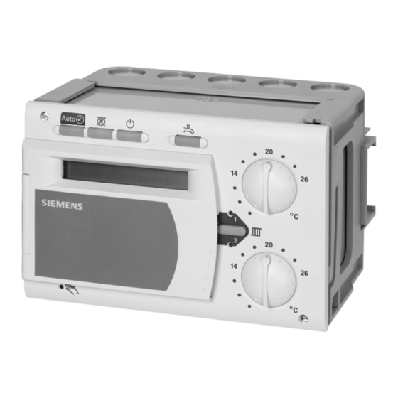
Handling 31.1 Operation 31.1.1 General Operating elements Front of the RVD240 Operating mode buttons for selecting the operating mode Display Line selection buttons for selecting operating lines Button and indication (LED) for manual operation ON / OFF Setting buttons for readjusting values Button for d.h.w. -
Page 105: Analog Operating Elements
The operating lines are grouped as blocks. To quickly select an individual operating line in a block, the other lines can be skipped. This is accomplished by using two combina- tions of buttons: 105/126 Siemens Building Technologies Basic documentation RVD240 CE1P2384en HVAC Products 31 Handling 27.05.2004... -
Page 106: Controller In "Nonoperated State
4. Select the operating lines. Information about the code of OEM versions is provided by the Siemens sales offices When changing to the next lower setting level, all settings of the higher setting level remain activated. 106/126... -
Page 107: Commissioning
Commissioning 31.2.1 Installation instructions The RVD240 is supplied with Installation Instructions which contain detailed descrip- tions of mounting and wiring and commissioning with functional checks and settings. They have been written for trained specialists. Each operating line has an empty field in which the selected value can be entered. -
Page 108: Electrical Installation
• The cables from the controller to the regulating unit and the pump carry mains volt- • Sensor cables should not be run parallel to mains carrying cable • The cores of the 2-wire cable to the PPS (room unit) are interchangeable 108/126 Siemens Building Technologies Basic documentation RVD240 CE1P2384en HVAC Products 31 Handling 27.05.2004... -
Page 109: Engineering
Control output for d.h.w. intermediate circuit / storage tank charging pump ON (depending on the type of plant) Control output for circulating pump ON The base contains 2 auxiliary terminals N and 109/126 Siemens Building Technologies Basic documentation RVD240 CE1P2384en HVAC Products 32 Engineering 27.05.2004... -
Page 110: Relays
• The protective function is ensured only if the installation is in proper working order For notes on installation in compliance with EMC requirements, refer to Data Sheet N2034. 110/126 Siemens Building Technologies Basic documentation RVD240 CE1P2384en HVAC Products 32 Engineering 27.05.2004... -
Page 111: Connection Diagrams
Input DC 0...10 V Actuator of 2-port valve in the primary return Actuator 2 (depending on the type of plant) Actuator 3 (depending on the type of plant) 111/126 Siemens Building Technologies Basic documentation RVD240 CE1P2384en HVAC Products 32 Engineering 27.05.2004... -
Page 112: Mechanical Design
Mechanical design 33.1 Basic design The RVD240 is comprised of controller insert, which accommodates the electronics, the power section, the output relays and – on the front – all operating elements, and the base, which carries the connection terminals. The RVD240 contains 9 relays. -
Page 113: Technical Data
37 m Copper cable ≥0.8 mm dia. 75 m Degrees of protection Degree of protection of housing to IEC 60529 IP 40D Safety class to EN 60730 113/126 Siemens Building Technologies Basic documentation RVD240 CE1P2384en HVAC Products 34 Technical data 27.05.2004... - Page 114 Special requirements for energy controllers EN 60730-2-11 Weight Net weight 0.84 kg For setting ranges, refer to the descriptions of the function blocks or of the individual operating lines. 114/126 Siemens Building Technologies Basic documentation RVD240 CE1P2384en HVAC Products 34 Technical data 27.05.2004...
- Page 115 ........109, 112 energy / volumetric flow pulses .........95 contact H5..............36 engineering .............109 continuous operation..........22 entries for LPB ............76 control of the circulating pump ........59 115/126 Siemens Building Technologies Basic documentation RVD240 CE1P2384en HVAC Products Index 27.05.2004...
- Page 116 ........98 generation of setpoint..........43 locking signals ............78 locking the settings ........... 91 handling..............104 low-voltage ............. 109 heat converter, control..........54 LPB parameters............76 heat demand signals (H5) .........55 116/126 Siemens Building Technologies Basic documentation RVD240 CE1P2384en HVAC Products Index 27.05.2004...
- Page 117 ......... 104, 112 raising the reduced setpoint ........96 operating instructions..........105 reduced d.h.w. temperature setpoint......31 operating line principle ..........105 reduced setpoint............28 operating lines............107 reduced setpoint raising ..........96 117/126 Siemens Building Technologies Basic documentation RVD240 CE1P2384en HVAC Products Index 27.05.2004...
- Page 118 ............40 wintertime ..............83 storage tank with electric immersion heater ....64 wiring ..............107 storage tanks.............63 stored heat ..............46 strain relief...............108 yearly clock............... 30 stratification storage tank ..........64 118/126 Siemens Building Technologies Basic documentation RVD240 CE1P2384en HVAC Products Index 27.05.2004...
- Page 119 External heat demand Extra overrun time of charging pump Flow alarm Flow temperature heating circuit Forced charging at the beginning of release phase 1 119/126 Siemens Building Technologies Basic documentation RVD240 CE1P2384en HVAC Products Alphabetical list of operating lines 27.05.2004...
- Page 120 Maximum speed of the speed-controlled pump Maximum time of d.h.w. heating M-bus power control in the heating circuit (Load Management) M-bus primary address M-bus secondary address 120/126 Siemens Building Technologies Basic documentation RVD240 CE1P2384en HVAC Products Alphabetical list of operating lines 27.05.2004...
- Page 121 Setpoint of legionella function Slope, increase of the reduced room temperature setpoint Slope, maximum limitation of the primary return temperature Software version Speed of speed-controlled pump 121/126 Siemens Building Technologies Basic documentation RVD240 CE1P2384en HVAC Products Alphabetical list of operating lines 27.05.2004...
- Page 122 Upper constant value, maximum limitation of the primary return temperature Weekday Weekday for entering the d.h.w. program Weekday for entering the heating program Winter- / summertime changeover Year 122/126 Siemens Building Technologies Basic documentation RVD240 CE1P2384en HVAC Products Alphabetical list of operating lines 27.05.2004...
- Page 123 Second paragraph added (maximum setpoint during legionella function) 27.1 Setting ranges operating lines 182 and 192 corrected 29.3.4 QAW70 line 3 changed 31.1.4 Entire subsection reworded; various changes Entire chapter added 123/126 Siemens Building Technologies Basic documentation RVD240 CE1P2384en HVAC Products Revision history 27.05.2004...
- Page 124 124/126 Siemens Building Technologies Basic documentation RVD240 CE1P2384en HVAC Products 27.05.2004...
- Page 125 125/126 Siemens Building Technologies Basic documentation RVD240 CE1P2384en HVAC Products 27.05.2004...
- Page 126 Siemens Building Technologies AG © 2000 Siemens Building Technologies AG HVAC Products Subject to alteration Gubelstrasse 22 CH 6301 Zug Tel. +41 41 724 24 24 Fax +41 41 724 35 22 www.landisstaefa.com 126/126 Siemens Building Technologies Basic documentation RVD240...
Need help?
Do you have a question about the RVD240 and is the answer not in the manual?
Questions and answers