Table of Contents
Advertisement
Quick Links
Installation Instructions
Model RPM
Remote Printer Module
INTRODUCTION
Features
P/N 315-033270-12
The Model RPM from Siemens Industry,
Inc., is an HNET module that interfaces
to a Centronics parallel printer. It must
be located where access to the
FireFinder-XLS/Desigo Fire Safety
Modular/Cerberus PRO Modular HNET
network and the PSC-12 24VDC power
limited output are available.
The RPM is required whenever a logging printer is needed. It translates
the HNET messages into a standard Centronics printer interface. When used
in conjunction with the PAL-1, it provides a supervised logging printer meeting the
requirements of NFPA 72 Proprietary or UL 1076 Security systems. For NFPA 72
Local, Auxiliary or Remote Station applications any UL EDP listed Centronics parallel
printer may be used (See notes 2, 3, and 4 on Figure 3).
The RPM also provides an optional Foreign System Interface (FSI). The FSI allows
other building systems to monitor the status of the FireFinder-XLS/Desigo Fire Safety
Modular/Cerberus PRO Modular system. The FSI connects to Ports 1-3 on the RPM.
This connection can be either RS-232 (Ports 1 or 3) or RS-485 (Port 2). Only one FSI
connection per RPM is allowed. The FireFinder-XLS/Desigo Fire Safety Modular/
Cerberus PRO Modular system supports a maximum of two simultaneous FSI
connections. With two simultaneous FSI connections the following combinations are
supported: Two Local FSI connections or one Global and one Local FSI connection. A
total of two Global FSI connections are supported in an XNET network. Each Global
FSI connection must originate from its own XLS/Desigo Fire Safety Modular/
Cerberus PRO Modular node.
RPM features are as follows:
•
Supervision of the PAL -1 includes paper out, paper jam, printer off line,
printer power off and printer disconnected.
•
Can be connected to the HNET either Style 4 or Style 7 .
•
Includes diagnostic LEDs to indicate failure of the HNET or the CPU. It also
has a power on indicator.
•
Includes a reset switch in the event that the RPM requires a hardware
reset.
•
Can be mounted on any smooth surface within 6 feet of the PAL -1.
•
Single Foreign System Interface (FSI) connection.
•
FSI supports Local (single system) or Global (multiple systems) operation.
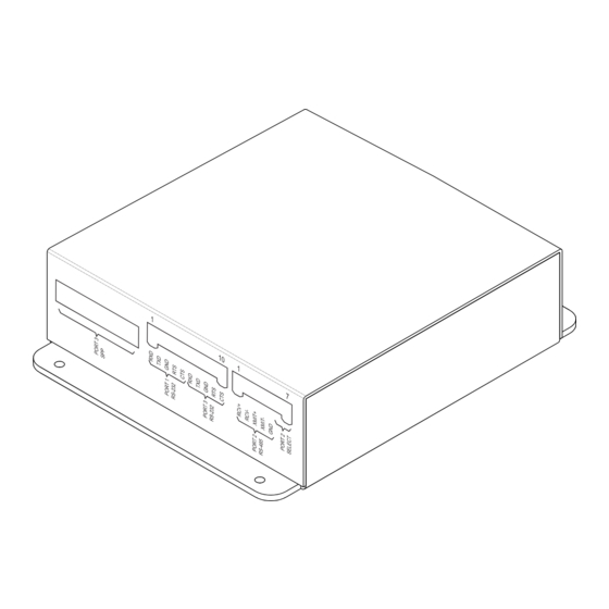
Figure 1
RPM Remote Printer Module
Siemens
Siemens
Siemens
Siemens
Siemens Industry
Industry, , , , , Inc.
Industry
Industry
Building
Building
Building
Building
Building T T T T T ec
ec
ec
echnologies Di
ec
hnologies Division
hnologies Di
hnologies Di
hnologies Di
Industry
Inc.
Inc.
Inc.
Inc.
vision
vision
vision
vision
Advertisement
Table of Contents

Subscribe to Our Youtube Channel
Related Manuals for Siemens RPM


Summary of Contents for Siemens RPM
- Page 1 Local, Auxiliary or Remote Station applications any UL EDP listed Centronics parallel printer may be used (See notes 2, 3, and 4 on Figure 3). The RPM also provides an optional Foreign System Interface (FSI). The FSI allows other building systems to monitor the status of the FireFinder-XLS/Desigo Fire Safety Modular/Cerberus PRO Modular system.
-
Page 2: Operation
Safety Modular), FCM2041-U3 (Cerberus PRO Modular) sends a print message to the RPM via HNET. The RPM is responsible for printing the message. The RPM contains a buffer to ensure that events that occur at a rate faster than the PAL -1 can print them are not lost. -
Page 3: Pre-Installation
NOTES: 1. The maximum distance from the RPM to the PAL -1 is 6 feet. The two modules must be in the same room. 2. For NFPA 72 Local, Auxiliary and Remote Station configurations, connect the output of the RPM to any UL EDP listed printer. -
Page 4: Terminal Block
Figure 5 Connecting Power To The RPM The RPM can be connected to the HNET either Style 4 or Style 7 . Refer to the Zeus configuration for the proper Style. In either case, the RPM can be connected in the middle of an HNET. - Page 5 NIC-C INSTALLED NIC-C INSTALLED 6. Reference NIC-C Installation Instructions, IN THE CC-5 IN THE CC-5 P/N 315-033240. Figure 7 RPM In The Middle Of A Style 7 HNET SUPERVISED & POWER LIMITED SHIELD DO NOT USE DO NOT USE NOTES: 1.
- Page 6 EDP or ETI listed. DATA FROM FOREIGN SYSTEM 8. Only ONE FSI (RS-232 or RS-485) connection allowed DATA TO FOREIGN SYSTEM per RPM. PORT 3* TO COMMON OF FOREIGN SYSTEM DO NOT USE DO NOT USE *PINS 6 & 7 ON THE PORT 2 CONNECTOR MUST BE STRAPPED TO ENABLE PORT 3.
-
Page 7: Installation
RPM. INSTALLATION The RPM mounts with two flanges on the side of the terminal block covers. Select a smooth surface within 6 feet of the PAL -1 for the RPM. Position the RPM and attach it to the mounting surface using the four #6 self tapping screws provided. - Page 8 Cyber security disclaimer Siemens products and solutions provide security functions to ensure the secure operation of building comfort, fire safety, security management and physical security systems. The security functions on these products and solutions are important components of a comprehensive security concept.
Need help?
Do you have a question about the RPM and is the answer not in the manual?
Questions and answers