Sign In
Upload
Manuals
Brands
WAGO Manuals
I/O Systems
750-402/025-000
WAGO 750-402/025-000 Manuals
Manuals and User Guides for WAGO 750-402/025-000. We have
2
WAGO 750-402/025-000 manuals available for free PDF download: Manual
WAGO 750-402/025-000 Manual (48 pages)
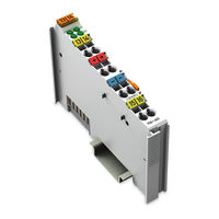
WAGO-I/O-SYSTEM 750 4DI 24V DC 3.0ms. 4-Channel Digital Input Module 24 V DC, 2- to 3-conductor connection; high-side switching
Brand:
WAGO
| Category:
I/O Systems
| Size: 1.68 MB
Table of Contents
Deutsch
3
Table of Contents
3
1 Notes about this Documentation
5
Validity of this Documentation
5
Copyright
5
Table 1: Variants
5
Symbols
6
Number Notation
8
Font Conventions
8
Table 2: Number Notation
8
Table 3: Font Conventions
8
2 Important Notes
9
Legal Bases
9
Subject to Changes
9
Personnel Qualifications
9
Use of the 750 Series in Compliance with Underlying Provisions
9
Technical Condition of Specified Devices
10
Safety Advice (Precautions)
11
3 Device Description
13
View
15
Connectors
16
Data Contacts/Internal Bus
16
Power Jumper Contacts/Field Supply
17
Table 4: Caption Acc. to View "Power Jumper Contacts
17
Cage Clamp
18
Connectors
18
Table 5: Caption Acc. to Figure "CAGE CLAMP ® Connectors
18
Display Elements
19
Table 6: Caption Acc. to Figure "Display Elements
19
Schematic Diagram
20
Technical Data
21
Device Data
21
Supply
21
Communication
21
Inputs
21
Table 7: Technical Data - Device
21
Connection Type
22
Climatic Environmental Conditions
22
Table 8: Technical Data - Field Wiring
22
Table 9: Technical Data - Power Jumper Contacts
22
Table 10: Technical Data - Internal Bus
22
Table 11: Technical Data - Climatic Environmental Conditions
22
Approvals
23
Standards and Guidelines
25
4 Process Image
26
Table 12: Input Bits
26
5 Mounting
27
Mounting Sequence
27
Inserting and Removing Devices
28
Inserting I/O Module
28
Removing the I/O Module
29
6 Connect Devices
30
Connecting a Conductor to the CAGE CLAMP
30
Connection Examples
31
2-Conductor Connection
31
7 Use in Hazardous Environments
32
Marking Configuration Examples
33
Marking for Europe According to ATEX and IEC-Ex
33
Table 13: Description of Marking Example for Approved I/O Modules According to ATEX and Iecex
34
Table 14: Description of Marking Example for Approved Ex I I/O Modules According to ATEX and Iecex
36
Marking for America According to NEC 500
38
Table 15: Description of Marking Example for Approved I/O Modules According to
38
Installation Regulations
39
Special Conditions for Safe Use (ATEX Certificate TÜV 07 ATEX 554086 X)
40
Special Conditions for Safe Use (ATEX Certificate TÜV 12 ATEX 106032 X)
41
Special Conditions for Safe Use (IEC-Ex Certificate TUN 09.0001
42
Special Conditions for Safe Use (IEC-Ex Certificate Iecex TUN 12.0039 X)
43
Ansi/Isa 12.12.01
44
English
45
Figure 1: View
15
Figure 2: Data Contacts
16
Figure 3: Power Jumper Contacts
17
Figure 4: CAGE CLAMP
18
Figure 5: Display Elements
19
Figure 6: Schematic Diagram
20
Figure 7: Insert I/O Module (Sample)
28
Figure 8: Snap the I/O Module into Place (Sample)
28
Figure 9: Removing the I/O Module (Sample)
29
Figure 10: Connecting a Conductor to a CAGE CLAMP
30
Figure 11: Connecting Diagrams - 2-Conductor Connection
31
Figure 12: Connecting Diagrams - 3-Conductor Connection
31
Figure 13: Side Marking Example for Approved I/O Modules According to ATEX and Iecex
33
Figure 14: Printing Text Detail - Marking Example for Approved I/O Modules According to ATEX and Iecex
33
Figure 15: Side Marking Example for Approved Ex I I/O Modules According to ATEX and Iecex
35
Figure 16: Text Detail - Marking Example for Approved Ex I I/O Modules According to ATEX and Iecex
35
Figure 17: Side Marking Example for I/O Modules According to NEC 500
38
Figure 18: Text Detail - Marking Example for Approved I/O Modules According to
38
List of Figures
45
List of Tables
46
Advertisement
WAGO 750-402/025-000 Manual (12 pages)
Fieldbus Independent I/O Module, 4 DI DC 24 V 3.0 ms, High-Side Switching
Brand:
WAGO
| Category:
I/O Systems
| Size: 0.37 MB
Table of Contents
Table of Contents
3
1 Important Comments
4
Legal Principles
4
Copyright
4
Personnel Qualification
4
Intended Use
4
Symbols
5
Number Notation
5
Safety Notes
6
Scope
6
2 O Modules
7
Digital Input Modules
7
750-402(/XXX-XXX) [4 DI DC 24 V 3.0 Ms, High-Side Switching]
7
Variations
7
View
7
Description
8
Display Elements
9
Schematic Diagram
9
Technical Data
10
Process Image
11
Advertisement
Related Products
WAGO 750-402
WAGO 750-404
WAGO 750-406
WAGO 750-408
WAGO 750-409
WAGO 750-430
WAGO 750-436
WAGO 750-479
WAGO 750-471
WAGO 750-461/003-000
WAGO Categories
I/O Systems
Control Unit
Power Supply
Switch
Circuit breakers
More WAGO Manuals
Login
Sign In
OR
Sign in with Facebook
Sign in with Google
Upload manual
Upload from disk
Upload from URL