Table of Contents
Advertisement
Advertisement
Table of Contents

Related Manuals for Eliwell RGF 312


Summary of Contents for Eliwell RGF 312
- Page 1 RGF 300 Three-phase voltage regulator...
- Page 2 WARNING ! HIGH LEAKAGE CURRENT: first connect to earth ! The rgf300 is a voltage regulator for three phase motors which operates connected to the three phase mains voltage. The regulator must be installed by qualified personnel who will connect the electric supply, attach the cables in their permanent positions and commission the plant.
- Page 3 SAFETY RULES ! This appliance has been designed to give excellent performance provided it is installed and used carefully in a suitable electric environment by qualified personnel. The following rules must be obeyed when installing the regulator : • Follow the instructions in this manual exactly and observe all safety measures in force. •...
- Page 4 CONTENTS ……………………………………………………..….…………………………… RESENTATION ……………………………………………………………………………….. ESCRIPTION …………………………………………….. NSTALLATION AND MACHANICAL DIMENSIONS …………………………………………………………………… RINCIPLE OF OPERATION 1.3.1 ………………………………………………………………… PERATING 1.3.2 ………………………………………………………………………. PPLICATION ………………………………………………………………………….. LECTRIC MOTORS 1.4.1 ……..…………………………………………… AGNETOTHERMAL PROTECTION ….………………………………………………………………. TECHNICAL DATA ………………………………………………………………………… LECTRICAL CONNECTIONS ……..……………………………………………. LECTRICAL CONNECTIONS POWER CARD ……...…………………………….. LECTRICAL CONNECTIONS ANALOGUE INPUT SIGNALS 2.2.1 ……………………………………...
-
Page 5: P Resentation
1.0 P RESENTATION for choosing an rgf300 series three phase voltage regulator, designed specifically to give the HANK YOU maximum yield and greatest ease of use. Like all our products, it has been built to the very highest quality standards using electronic components of the utmost reliability which have undergone functional tests that guarantee use of the product for at least 30,000 hours of continuous operation without problem. - Page 6 Like all our products, the rgf300 series bears CE marking as required by directive 89/336/ECC and its subsequent modification EEC/92/31 on electromagnetic compatibility. Since all these products are not used as "stand alone" appliances but incorporated into other plants or machines, the standards' compatibility test was carried out under typical operating conditions.
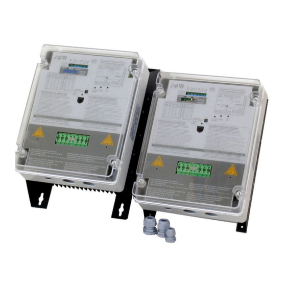
- Page 7 Fig. 3 represent the rgf300 regulator with the general contents fig. 3 CONTENTS of rgf300 regulator Control Trimmer for work parameters regulation Double 10 positions rotary switch for Set-point (optional) Reference table for Set-point rotary centesimal switch Lexan internal panel for protection against direct contact Terminal block for analog inputs/output signals Control card (upper) Power card (lower)
-
Page 8: D Escription
DESCRIPTION The rgf300 series three-phase cutting regulators comprises two electronic cards on a vetronite support mounted inside the GEWISS IP55 GW Plast 120°C case. The two cards represent the control section (upper) and power section (lower). P2 P3 = soft-start Proportional Band Set-Point... - Page 9 ALARM ALARM HELPi UNIT Heat - Pump fig. 5 Mechanical Dimensions ∅ ∅ ∅ ∅ Fixing MODELS screw holes ∅ 6 rgf 312 ∅ 6 rgf 320 ∅ 6 rgf 325 ∅ 6 rgf 340 11.0 ∅ 8 rgf 360 17.0...
- Page 10 Table 1 RGF 300 10/53...
-
Page 11: P Rinciple Of Operation
PRINCIPLE OF OPERATION The rgf300 series appliances are voltage regulators that use the phase cutting principle totally controlled over three phases. The regulators, also referred to as speed controls, have been designed to change the average voltage on the following types of equipment, according to a control signal: •... -
Page 12: O Perating
After the motor characteristics have been checked, the following should be defined in order to identify the type of operating mode and application. 1.3.1 Operating mode The rgf controls allow two different types of operation depending on which type of input is available: •... -
Page 13: E Lectric Motors
Installation of magnetothermal protections is the responsibility of the installer. It is advisable to fit an automatic magnetothermal protection with a 'C' intervention curve having the following capacity: magnetothermal RGF 300 models carrying capacity rgf 312 20 A rgf 320 30 A rgf 325 36 A... - Page 14 50 Hz (60 Hz) UPPLY Overvoltage protection for installation Category II (4 KV) RGF 312 12 A up to 50°C environment, over decrease by 0.6 A/°C 20 A up to 50°C environment, over decrease by 1.0 A/°C RGF 320 Rated 25 A up to 50°C environment, over decrease by 1.2 A/°C...
-
Page 15: E Lectrical Connections
EMC integrated mains filter ISM appliances directly connected to low voltage power mains According to EN 61000-4-5 : overvoltage Category II (4 KV) Overvoltage protection RGF 312 286 x 201 x 130 mm 4.0 kg RGF 320 351 x 237 x 181 mm 5.5 kg... -
Page 16: C Onnection Of
2.0 ELECTRICAL CONNECTIONS POWER CARD ELECTRICAL CONNECTIONS For supply and load connection, reference should be made to the diagrams shown in fig. 8, making sure the section of the cables is adequate to the connected load. The power cables (supply and load) must be installed separately from the control cables (analogue inputs and ON-OFF inputs/outputs) keeping the maximum distance possible between the conductors. - Page 17 fig. 9 RGF 300 17/53...
- Page 18 ELECTRICAL CONNECTIONS, ANALOGUE INPUT SIGNALS The connections for the control analogue inputs are described below. They can be connected to the MA terminal board, in particular: MASTER version Active sensors with control in current (mA) or voltage (Vdc) MASTER version NTC sensors with control in °C ( 10 kohm @ 25 °C ) SLAVE version...
- Page 19 One of the main applications of the rgf300 series regulators is the control of voltage and speed of rotation of fans. This is modulated to keep temperature or pressure constant as a work point for one or more refrigerating circuits (condensator or evaporator mode).
- Page 20 2.2.2 Connection of NTC temperature sensors (10kohm @ 25 °C) Two versions of NTC temperature sensors are available for rgf300 models: • X for scale +10 °C to +60 °C • Y for scale - 20 °C to +20 °C The table below lists the information necessary for calibration of the Set-point (page 34) with the position of P3 referred to the centesimal Commutators (Com.) or Trimmer (Trim.), and for calibration of the Proportional Band with the position of P2.
-
Page 21: C Onnection Of Other Sensors And Control Signals
2.2.3 Connection of other sensors and control signals Active sensors with : 0-20 / 4-20 mA current output (M vers.), and 0-10 Vdc voltage output (V vers.) Connection can usually be made to the rgf300 regulator with one or two active sensors, with current output control signal (0-20 mA) or voltage output (0-10 Vdc) with conductors having two or three wires. - Page 22 2.2.4 Remote connection for a current (mA) or voltage (Vdc) control signal Connection of an external control unit (for SLAVE M, V) If regulator control from an external unit is required, choose one of the following versions: SLAVE M when the external control unit uses a current control signal (0-20 mA), or SLAVE V when the external control unit uses a voltage control signal (0-10 Vdc).
- Page 23 fig. 14 RGF 300 23/53...
-
Page 24: C Onnection Of The Rgf
2.2.5 Connection of the rgf MULTIDRIVER control In this configuration, the rgf300 regulator is able to guide other single or three phase rgf regulators through the MA 9 (OUT) and MA 10 (GND) terminals. The control output controlled by jumper J6 allows a signal to be sent to several SLAVE (M or V) units. The signal takes account of the work settings on the main rgf300. -
Page 25: O Perating Selection
ELECTRICAL CONNECTIONS, ON-OFF INPUTS/OUTPUT This paragraph describes the connections to the auxiliary S1 - S2 - S3 and TK, ON-OFF inputs / output available on the ‘MB’ terminal board for which the electrical connection is made with 0- signal POTENTIAL cables. - Page 26 The operation described here can be achieved by means of electromechanical devices. However it is extremely simple if the cutting regulators is controlled by an external regulator (e.g. Energy Light - type Eliwell), which can automatically control the S1 contact. S2: STOP (MB 4 – MB 5 terminals)
- Page 27 RL1: ALARM relay (MB 8-9-10 terminals) with J14 selection jumper The RL1 relay is mounted on the control card. The relay has a commutation contact for external signalling of the operating status. For the operation mode of this output relay, configure jumper J14 so that all alarms are enabled, as shown in the table below: POWER SUPPLY T.K.
-
Page 28: C Ommissioning Procedure
3.0 COMMISSIONING PROCEDURE Having carried out the electrical connections to the regulator, it is time to perform the configuration, regulation and commissioning operations for the rgf300 regulator by following the procedure below. It is important to remember that the settings of the jumpers (Jn) are only to be modified to change the configuration or the operating mode of the regulator set in the factory (check the label on the right side of the casing). -
Page 29: Master
Selects the operating mode of output MA 9/10 in combination with jumper J6. Selects the work field of the Proportional Band in °C, mA, Vdc : J5 = ON1 P2 scale for control input with NTC (ohm) sensors for °C (range 3 – 30 °C) J5 = ON2 P2 scale for control input with active sensors from 4-20 mA (range 0.4 –... - Page 30 Selects the RESET operating mode of the TK contact (terminal board MB 6/7): J13 = ON1 when selected, if the TK protection intervenes, the regulator must be switched off and on again to reset the system after the cause has been eliminated ( MANUAL RESET J13 = ON2 when selected, if the TK protection intervenes, the system restarts automatically after...
- Page 31 MASTER, version M (4-20 mA), for 1 or 2 control INPUTS = Soft-Start = Proportional Band = Set-Point = max. output = min. output = Cut-off = MANUAL (mode H.P.) T.K. RL 1 ALARM AC LINE ALARM HEAT PUMP 1 2 3 4 5 6 7 8 9 10 1 2 3 4 5 6 7 8 9 10 fig.
- Page 32 SLAVE, version M (0-20 mA), for 1 or 2 control INPUTS = Soft-Start Set - 100% output standing = max. output = min. output = Cut-off = MANUAL (mode H.P.) T.K. RL 1 ALARM AC LINE ALARM HEAT PUMP 1 2 3 4 5 6 7 8 9 10 1 2 3 4 5 6 7 8 9 10 fig.
- Page 33 MASTER, version X or Y (NTC °C), for 1 or 2 control INPUTS = Soft-Start = Proportional Band = Set-Point = max. output = min. output = Cut-off = MANUAL (mode H.P.) T.K. RL 1 ALARM AC LINE ALARM HEAT PUMP 1 2 3 4 5 6 7 8 9 10 1 2 3 4 5 6 7 8 9 10...
- Page 34 Optional module for dual Set-point configuration (SP1 – SP2) The rgf300 regulator can be used in versions MASTER M, V, X, Y with a reference dual Set-point by using the optional module card RGFPB10640 for double control Set-points. Insert the card in the CN3 connector on the rgf300 regulator (see the position in fig. 25). When the card is positioned, with J2=ON2, Trimmer P3 is disabled (standing) and substituted by two pairs 99 position digital commutators.
-
Page 35: Control Trimmer
4.0 CONTROL TRIMMER WARNING : Before starting the regulator calibration phase, check the position of the trimmers as shown in figs. 26 and 27. The position of the trimmers marked with a spot of red paint (factory calibrated trimmers) must not be altered. fig. - Page 36 MAX. OUTPUT regulation (P4 trimmer) - PHASE 1 100% P4 100% P4 80% Max. output setting fig. 29 Limits the maximum operating voltage (from 100% to 0%). It is useful for limiting the maximum capacity or noise of the fan when turning at max. OUTPUT speed.
-
Page 37: Cut-Off Regulation
CUT-OFF regulation (P6 trimmer) - PHASE 1 P6 20% CUT-OFF P6 0% setting fig. 31 Adjusts the minimum voltage being supplied to the fan during automatic operation: the fan will not be supplied with voltage lower than the predetermined value; this avoids the supply of minimum voltage which would not be sufficient to provide a starting torque for the fan rotation. -
Page 38: P Roportional
PROPORTIONAL BAND regulation (P2 trimmer) - PHASE 2 Trimmer P2 takes on different roles depending on the model of rgf300 chosen: on 'Master' operation models (M,V,X,Y), P2 adjusts the proportional band. ROPORTIONAL on 'Slave' operation models (M and V), trimmer P2 is set at the factory to give maximum voltage to the load corresponding to the maximum control signal sent to the regulator. - Page 39 Version M for 4/20 mA active sensors: 0.4 mA (trimmer in position 'm' ) ranges from: 2.1 mA (trimmer in position 'c' ) 4.0 mA (trimmer in position 'M' ). The current signal is tied to the scale amplitude of the transducer used. In the case of pressure control (which occurs most frequently), the value of the mA/Bar ratio changes depending on the pressure transmitter scale.
- Page 40 SET-POINT regulation (models M, V, X, Y) P3 trimmer - PHASE 2 It is possible to activate the SET-POINT (the automatic regulation start point) by activating the P3 trimmer. SET POINT In the standard configuration, the Set-Point coincides with the maximum value of supply (100% or value of P4 max.
- Page 41 4.5.1 Centesimal SET-POINT option (mod. M, V, X, Y) P3 - FHASE 2 In the MASTER configuration, the RGF300 can be chosen with the RGFPB1064 OPTION. This plug support the Set-point (P3), with double digital commutators for DUAL Set-Point (S3 SIMPLY switch) in 99 setting positions.
-
Page 42: M Anual Regulation
SOFT-START regulation (P1 trimmer) Adjusts the rapidity with which the fan speed varies ('slow start' and 'slow stop'); in practice it makes the system 'slow' or 'fast' depending on the change in the automatic control Soft-Start signal. In the 'M' position (trimmer completely turned clockwise), the variation speed is slowed to m = 2”... - Page 43 5.0 HELPI 10: PORTABLE DISPLAY UNIT All calibration operations described can easily be carried out with the portable module called HELP 10 for display of work parameters. All three phase regulators in the rgf300 series are fitted with the CN2 connector located between the MA and MB terminal boards.
- Page 44 HELP UMMARY TABLES FOR USE OF THE DISPLAY MODULE Technical characteristics Supply voltage 22 V ( 18..36 V ) From the connected appliance 0 - 15 bar Can be changed via the 4 - 20 mA 0 - 25 bar keyboard to: 0 - 30 bar Input...
- Page 45 COMMISIONING PROCEDURE : Function keys > Regulation (Trimmer) > Displays (M2) (M3) (M1) Trimmer P1 = Soft-Start starting P2 = Proportional Band position P4 = max. output P5 = min. output P6 = Cut-off P7 = MANUAL (mode H.P.) T.K. RL 1 ALARM AC LINE...
- Page 46 RGF 300 46/53...
- Page 47 How to use the HELP 10 display module • Connect the HELP 10 unit to the regulator to calibrate using the supplied cable; this can be done with the regulator powered up and operating but without transducers or sensors connected •...
-
Page 48: Rgf 300 Easy Reference Commissioning Guide
6.0 rgf 300 EASY REFERENCE COMMISSIONING GUIDE Having connected the supply and load to the regulator, the control system commissioning operation must be divided into two phases in order to separate the definition of the regulator work voltage limits (P4-P5-P6) from the surround control values (P3-P2 with mA - Vdc - °C) in automatic regulation: QUESTION ANSWER... - Page 49 “SLAVE” CONFIGURATION with control in mA / Vdc With this configuration, once the P4, P5 and P6 reference parameters have been defined, the regulator carries out speed changes on the basis of the control values which are transmitted by the external controller, without needing further calibration.
-
Page 50: Troubleshooting
7.0 TROUBLE SHOOTING Some of the problems which may occur during or after unit commissioning are listed below with their possible solutions. Problem Cause Solution Unit supplied but load does not activate. C1. Absence of one or two phases (Led S1. -
Page 51: L Iability And
- installation/use on boards not complying with the standards and provisions of current legislation. 9.0 DISCLAIMER This manual and its contents remain the sole property of Eliwell & Controlli s.r.l., and shall not be reproduced or distributed without authorization. Although great care has been exercised in the preparation of this document, Eliwell &... - Page 52 TECHNICAL ASSISTANCE SHEET 1. All rgf equipment is guaranteed for 36 months from the date of testing. 2. The guarantee is rendered invalid under these circumstance: • evidence of tampering with the mechanics or electrics • improper use • incorrect installation •...
- Page 53 Rgf300 INSTALLATION FEATURES FAN FEATURES rgf FEATURES Serial N° N° Model Load (Amp) Power Supply Model PROBE FEATURES TYPE N° MODEL RANGE CONNECTION Pressure Transducer NTC probe Transducer . . . WORKING PARAMETERS FACTORY TRIMMER % OUTPUT VAC OUTPUT VAC SUPPLY OPERATOR SETTING MAX.
- Page 54 RGF 300 rel. 11/03 eng cod. 8MA10033...
Need help?
Do you have a question about the RGF 312 and is the answer not in the manual?
Questions and answers