Table of Contents
Advertisement
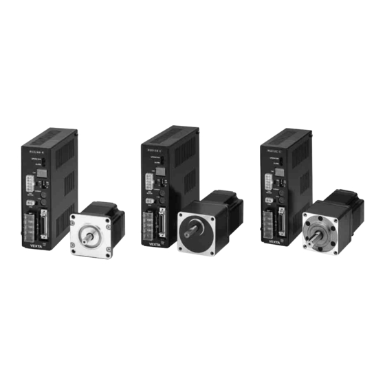
AS Series
OPERATING MANUAL
AS66, AS69, AS98, AS911
C
Thank you for purchasing an Oriental Motor product.
This Operating Manual describes product handling procedures and safety precautions.
• Please read it thoroughly to ensure safe operation.
• Always keep the manual where it is readily available.
Table of Contents
Introduction ........................................... Page 2
Safety precautions ................................ Page 4
Precautions for use ............................... Page 6
Preparation ........................................... Page 8
Checking the product ......................... Page 8
Names and functions of parts ............ Page 14
Installation ............................................ Page 16
Location for installation ...................... Page 16
Installing the motor ............................ Page 16
Installing a load .................................. Page 17
Overhung load and thrust load .......... Page 18
Installing the driver ............................ Page 19
Installing and wiring in compliance
with EMC directive ...... Page 22
Connection ........................................... Page 25
Connecting the driver ........................ Page 26
Connecting to the power supply ........ Page 28
Connecting the motor ........................ Page 31
Grounding the motor and driver ......... Page 33
Connecting control input/output ......... Page 33
About control input/output .................. Page 36
Timing chart ....................................... Page 42
Setting .................................................. Page 43
Resolution ......................................... Page 43
Pulse input modes ............................. Page 44
Operating current .............................. Page 44
Speed filter ........................................ Page 45
Protective functions .............................. Page 46
Inspection ............................................. Page 47
Troubleshooting and remedial actions .. Page 48
Main specifications ............................... Page 50
Appendix .............................................. Page 61
HM-6159-11
standard type .... Page 25
1
Advertisement
Table of Contents

Summary of Contents for Vexta aStep AS Series
-
Page 1: Table Of Contents
HM-6159-11 AS Series OPERATING MANUAL Table of Contents AS66, AS69, AS98, AS911 Introduction ........... Page 2 Safety precautions ........ Page 4 Precautions for use ....... Page 6 Preparation ........... Page 8 Checking the product ......Page 8 Names and functions of parts .... Page 14 Installation .......... -
Page 2: Introduction
Introduction Before using the motor unit Only qualified personnel should work with the product. Use the product correctly after thoroughly reading the section “Safety precautions.” The product described in this manual has been designed and manufactured for use in general industrial machinery, and must not be used for any other purpose. - Page 3 100- Motor 115V VEXTA Control input and output • Be sure to purchase the extension cable (for use in the model with electromagnetic brake), which is sold separately, when using the model with the electromagnetic brake. When the motor cable is directly connected to the driver, the electromagnetic brake will not work.
-
Page 4: Safety Precautions
Safety precautions The precautions described below are intended to prevent danger or injury to the user and other personnel through safe, correct use of the product. Use the product only after carefully reading and fully understanding these instructions. Warning Handling the product without observing the instructions that accompany a “Warning” symbol may result in serious injury or death. - Page 5 Maintenance and inspection • Do not touch the connection terminals of the driver immediately after the power is turned off (for a period of 10 seconds). The residual voltage may cause electric shock. Repair, disassembly and modification • Do not disassemble or modify the motor or driver. This may cause electric shock or injury. Refer all such internal inspections and repairs to the branch or sales office from which you purchased the product.
-
Page 6: Precautions For Use
Precautions for use AS series. This section covers limitations and requirements the user should consider when using the • Operate the motor at a level below the maximum torque. Operating the motor beyond the maximum torque or placing a continuous constraint on the output shaft may damage the motor bearings (ball bearings). - Page 7 • Preventing electrical noise See “Installing and wiring in compliance with EMC directive” on page 22 for measures with regard to noise.
-
Page 8: Preparation
Preparation This section covers the points to be checked along with the names and functions of respective parts. Checking the product Upon opening the package, verify that the items listed below are included. Report any missing or damaged items to the branch or sales office from which you purchased the product. Verify the model number of the purchased unit against the number shown on the package label. - Page 9 How to identify the product model Geared type A S 6 6 A A 2 - H 50 Gear ratio Gear type T: TH gear P: PL gear N: PN gear H: Harmonic gear Power input A: Single-phase 100-115 V C: Single-phase 200-230 V S: Three-phase 200-230 V Motor type...
- Page 10 Combinations of motors and drivers TH geared type Standard type Electromagnetic-brake type Unit model Motor model Driver model Unit model Motor model Driver model AS66AA-T3.6 ASM66AA-T3.6 ASD24B-A AS66MA-T3.6 ASM66MA-T3.6 ASD24B-A AS66AA-T7.2 ASM66AA-T7.2 ASD24B-A AS66MA-T7.2 ASM66MA-T7.2 ASD24B-A AS66AA-T10 ASM66AA-T10 ASD24B-A AS66MA-T10 ASM66MA-T10 ASD24B-A AS66AA-T20...
- Page 11 PL geared type Standard type Electromagnetic-brake type Unit model Motor model Driver model Unit model Motor model Driver model ASM66MA-P5 ASD24A-A AS66AA-P5 ASM66AA-P5 ASD24A-A AS66MA-P5 ASM66MA-P7.2 ASD24A-A AS66AA-P7.2 ASM66AA-P7.2 ASD24A-A AS66MA-P7.2 ASM66MA-P10 ASD24A-A AS66AA-P10 ASM66AA-P10 ASD24A-A AS66MA-P10 AS66AA-P25 AS66MA-P25 ASM66MA-P25 ASD24B-A ASM66AA-P25 ASD24B-A...
- Page 12 PN geared type Standard type Electromagnetic-brake type Unit model Motor model Driver model Unit model Motor model Driver model AS66MA-N5 ASM66MA-N5 ASD24A-A AS66AA-N5 ASM66AA-N5 ASD24A-A AS66MA-N7.2 ASM66MA-N7.2 ASD24A-A AS66AA-N7.2 ASM66AA-N7.2 ASD24A-A AS66MA-N10 ASM66MA-N10 ASD24A-A AS66AA-N10 ASM66AA-N10 ASD24A-A AS66AA-N25 AS66MA-N25 ASM66MA-N25 ASD24B-A ASM66AA-N25 ASD24B-A...
- Page 13 Harmonic geared type Standard type Electromagnetic-brake type Unit model Motor model Driver model Unit model Motor model Driver model AS66AA2-H50 ASM66AA2-H50 ASD24B-A AS66MA2-H50 ASD24B-A ASM66MA2-H50 AS66MA2-H100 ASD24C-A AS66AA2-H100 ASM66AA2-H100 ASD24C-A ASM66MA2-H100 AS66MC2-H50 ASD12B-C AS66AC2-H50 ASM66AC2-H50 ASD12B-C ASM66MC2-H50 AS66AC2-H100 ASM66AC2-H100 ASD12C-C AS66MC2-H100 ASD12C-C ASM66MC2-H100...
-
Page 14: Names And Functions Of Parts
Names and functions of parts This section covers the names and functions of parts in the motor and driver. For further details on each part, refer to the page shown in the square bracket. Motor Pilot Mounting holes (four locations) [P.16] Motor cable [P.31,32] Output shaft Electromagnetic brake [motor with an electromagnetic brake] [P.32,41]... - Page 15 The factory setting is "6: 1.20 ms." Control input/output connectors (CN4) [P.25,26,27,33,34,35] Used to connect to the motor-positioning control and others. Protective earth terminal [P.33] VEXTA Used for grounding via a grounding cable of AWG18 (0.75 mm ) or more.
-
Page 16: Installation
Installation This section covers the environment and method of installing the motor and driver, along with load installation. Also covered in this section are the installation and wiring methods that are in compliance with the relevant EMC directives (89/336/EEC, 92/31/EEC). Location for installation The motor and driver are designed and manufactured for installation in equipment. -
Page 17: Installing A Load
Installing a load When connecting a load to the motor, align the centers of the motor’s output shaft and load Note shaft. • When coupling the load to the Optional flexible couplings are available (sold separately). motor, pay attention to the centering of the shafts, belt tension, parallelism of the Direct coupling... -
Page 18: Overhung Load And Thrust Load
Overhung load and thrust load The overhung load on the motor’s output shaft or gear output shaft must be kept within the Note permissible values listed below. Failure due to fatigue may occur if the motor’s bearings and The thrust load must not exceed the motor’s mass. output shaft are subject to repeated loading by an overhung Overhung load [N (lb.)]... -
Page 19: Installing The Driver
Installing the driver Orientation The driver is designed so that heat is dissipated via air convection and conduction through the Note enclosure. • Install the driver in an enclosure. • Do not install any equipment When installing the driver in an enclosure, it must be placed in perpendicular (vertical) that generates a large amount orientation using a DIN rail or driver mounting brackets. - Page 20 OPERATION OPERATION ALARM ALARM 1000 1000 CURRENT CURRENT MOTOR MOTOR V.FIL V.FIL 100- 100- 115V 115V VEXTA VEXTA 25 mm (0.98 in.) 25 mm (0.98 in.) minimum ASD24A-A ASD24A-A OPERATION OPERATION ALARM ALARM 1000 1000 CURRENT CURRENT MOTOR MOTOR V.FIL V.FIL...
- Page 21 (2.2 to 4.41 lb.) to pull the DIN lever to lock it. Excessive force may damage the DIN lever. • Use an end plate (not supplied) to secure the driver. ASD24A-A OPERATION ALARM 1000 CURRENT MOTOR V.FIL 100- 115V End plate VEXTA...
-
Page 22: With Emc Directive
Installing and wiring in compliance with EMC directive General EMC directive (89/336/EEC, 92/31/EEC) AS series has been designed and manufactured for incorporation in general industrial machinery. The EMC directive requires that the equipment incorporating this product comply with these directives. The installation and wiring method for the motor and driver are the basic methods that would effectively allow the customer’s equipment to be compliant with the EMC directive. - Page 23 How to ground The cable used to ground the driver, motor and mains filter must be as thick and short to the grounding point as possible so that no potential difference is generated. Choose a large, thick and uniformly conductive surface for the grounding point. How to ground the driver Single-phase 100/200 V input Three-phase 200 V input...
- Page 24 OPERATION ALARM 1000 NORM. TEST CURRENT MOTOR V.FIL 100- 115V VEXTA A: Motor cable B: Mains filter C: Cable clamp D: Protective earth cable E: Signal cable F: Power cable G: Surge arrester Precautions about static electricity Note Static electricity may cause the driver to malfunction or suffer damage. Be careful when handling the driver with the power on.
-
Page 25: Connection
Controller 100-115 V 100- 115V − 50 / 60 Hz Connect to CN4 VEXTA Protective earth Connection example for an electromagnetic-brake type Note Be sure to use the extension cable for the electromagnetic- brake type (sold separately) to Power supply for an electromagnetic brake... -
Page 26: Connecting The Driver
Connecting the driver Note • Either 5 or 24 VDC is selected as a signal voltage for the C.OFF input, ×10 input and ACL input. • The TIM1/TIM2 outputs, ASG1/ASG2 outputs and BSG1/BSG2 outputs require a 5 or 24 VDC power. Be sure to use the same voltage for C.OFF, ×10 and ACL inputs In case of current sourcing inputs and current sinking outputs... - Page 27 In case of current sinking inputs and current sourcing outputs Note Be sure to use the same voltage Controller Driver for C.OFF, ×10 and ACL inputs +5 V and TIM1/TIM2, ASG1/ASG2 Twisted pair cable or shielded cable and BSG1/BSG2 outputs. CW input CW input Connecting both 5 and 24 VDC...
-
Page 28: Connecting To The Power Supply
Connecting to the power supply Connect the power cable to the L and N terminals or the L1, L2 and L3 terminals of the power-supply terminals located on the driver. For single-phase 100-115 V unit Connect the live side of the single-phase 100-115 V power cable to the L terminal and the Note neutral side to the N terminal. - Page 29 For single-phase 200-230 V unit Connect the live side of the single-phase 200-230 V power cable to the L terminal and the neutral side to the N terminal. Connect the terminal to the grounding point of the power source. Single-phase 200- 230V 200-230 V...
- Page 30 For three-phase 200-230 V unit Connect the U, V and W phase lines of the three-phase 200-230 V power cable to the L1, L2 and L3 terminals, respectively. Three-phase 200-230 V 50/60 Hz Use a power supply capable of supplying the power/current capacity as shown below. Unit name Power/current capacity AS66AS-T...
-
Page 31: Connecting The Motor
Connecting the motor Standard type Plug the connector of the motor cable or the extension cable into the driver’s motor connector Note (CN2). • Have the connector plugged in Push the plug until it clicks to ensure a solid connection. securely. - Page 32 Connecting power supply for the electromagnetic brake Provide a DC power-supply cable of 24 VDC±5% at 0.3 A or more. Note Use a shielded cable of AWG24 (0.2 mm ) or more in diameter to connect the electromagnetic • Applying a voltage over the brake to the DC power supply, keeping the length as short as possible.
-
Page 33: Grounding The Motor And Driver
Grounding the motor and driver Grounding the motor Ground the motor using one of its four mounting holes. Use a grounding cable of AWG18 (0.75 mm ) or more in diameter. Use a round, insulated crimp terminal in combination with an inner-clip washer and bolt it in place to secure the grounding connection. - Page 34 Assembling the control input/output connector Solder the control input/output cable to the half-pitch connector (36 pins), then install the connector cover over the half-pitch connector. Soldering the cable to the half-pitch connector Solder the input/output signal cable (AWG28: 0.08 mm or more) to the half-pitch connector (36 pins).
- Page 35 Connector pin functions Note • The functions shown in Pin No. Signal Description Direction parentheses are enabled when “1P: 1-Pulse Input Mode” is Vcc+5 V 5 VDC External power selected through the pulse- Input source input mode selector switch. Vcc+24 V 24 VDC •...
-
Page 36: About Control Input/Output
About control input/output Input signals Note All input signals of the driver are photocoupler inputs. Be sure to use the same voltage For C.OFF input, ×10 input and ACL input a signal voltage of either 5 or 24 VDC can be for C.OFF, ×10 and ACL inputs selected. - Page 37 1-pulse input mode Connect the pulse signal of the controller to pin No.11 and No.12, and the rotating direction signal to pin No.9 and No.10, respectively. When the DIR input is “ON,” a rise of the “PLS input” from “OFF” to “ON” will rotate the motor one step in the CW direction.
- Page 38 C.OFF (All windings off) input Note Use the signal only when the motor’s output shaft must be rotated manually for position adjustment. • Normally, keep the C.OFF input in the “OFF” state or leave it Warning • Do not turn the C.OFF (All windings off) input to “ON” while the motor is disconnected.
- Page 39 Output signals Note Driver output signals are photocoupler/open-collector output, transistor open-collector output Be sure to use the same voltage for the TIM1, ASG1 and BSG1 outputs, and line-driver output for the TIM2, ASG2 and BSG2 for C.OFF, ×10 and ACL inputs outputs.
- Page 40 TIM (Timing) output Note TIM output are available in two types: transistor open-collector output and line-driver output. Use either one to suit the input system of the positioning controller. If TIM output is to be detected, set the pulse speed at 500 Hz or The use of TIM output requires separate 5 or 24 VDC power.
- Page 41 Operating the electromagnetic brake Operate the electromagnetic brake as follows: Note To hold the load in position, apply ALARM output is in the “OFF” state immediately after the driver power is turned on. the electromagnetic brake only after the motor has stopped. Do Check to see that ALARM output has been reset (turned from OFF to ON), then turn on the not use the brake to bring the electromagnetic brake.
-
Page 42: Timing Chart
Timing chart Motor operation 10 s minimum Power input ∗1 0.5 s maximum 0.1 s minimum ALARM output (Alarm) ∗2 CW pulse input CCW pulse input ∗3 ∗3 ∗3 END output (Positioning complete) 2 s minimum ∗4 TIM output (Timing) ∗5 C.OFF input (All windings off) -
Page 43: Setting
Setting This section covers the selection and settings of driver functions. The various switches provided on the driver’s front panel allow for the setting of resolution, pulse-input mode, current level and speed filter. Warning • Before working on the system, shut off the power to the driver and wait 10 seconds. -
Page 44: Pulse Input Modes
Pulse input modes Note Either the 2-pulse or 1-pulse input mode may be selected in accordance with the controller used. Be sure to shut off the power before using the pulse-input mode selection switch. Factory setting The new pulse mode takes effect [2P]: 2-Pulse Input Mode when the power is turned on again. -
Page 45: Speed Filter
Speed filter Use the speed-filter selection switch “V.FIL” to select the filter time constant that determines the motor’s response to pulse input. The switch provides a selection of 16 levels ranging between “0” and “F.” When a larger value is selected, it will reduce shock when the motor is started and stopped, and will minimize low-speed vibration. -
Page 46: Protective Functions
Protective functions This section covers the driver-protection functions and methods used to clear the triggered function. Warning • When the driver-protection function is triggered, the motor will stop and lose its holding torque, possibly causing injury or damage to equipment. •... -
Page 47: Inspection
Inspection Note It is recommended that periodic inspections be conducted for the items listed below after each The driver uses semiconductor operation of the motor. elements, so be extremely If an abnormal condition is noted, discontinue any use and contact your nearest office. careful when handling them. -
Page 48: Troubleshooting And Remedial Actions
Troubleshooting and remedial actions During motor operation, the motor or driver may fail to function properly due to an improper speed setting or wiring. When the motor cannot be operated correctly, refer to the contents provided in this section and take appropriate action. If the problem persists, contact your nearest office. - Page 49 If the ALARM LED is blinking If the ALARM LED is blinking, count the number of blinks and refer to the table below: The ALARM LED blinks in two modes: blinking in groups of between 1 and 8 times (0.2 second on and 0.2 second off) and repeating the same number after 1.2 second each;...
-
Page 50: Main Specifications
Main specifications AS series. This section covers the main specifications of the Refer to the catalog for detailed specifications, torque characteristics and dimensions. Driver Motor Protective range IP10 IP20 0°C to +50°C (+32°F to +122°F) 0°C to +50°C (+32°F to +122°F) (non-freezing) (non-freezing) Ambient temperature... - Page 51 TH geared type AS66AA-T3.6 AS66AA-T7.2 AS66AA-T10 AS66AA-T20 AS66AA-T30 Single-phase100-115 V AS66AC-T3.6 AS66AC-T7.2 AS66AC-T10 AS66AC-T20 AS66AC-T30 Standard type Single-phase200-230 V AS66AS-T3.6 AS66AS-T7.2 AS66AS-T10 AS66AS-T20 AS66AS-T30 Three-phase200-230 V AS66MA-T3.6 AS66MA-T7.2 AS66MA-T10 AS66MA-T20 AS66MA-T30 Single-phase100-115 V Electromagnetic- AS66MC-T3.6 AS66MC-T7.2 AS66MC-T10 AS66MC-T20 AS66MC-T30 Single-phase200-230 V brake type AS66MS-T3.6 AS66MS-T7.2...
- Page 52 TH geared type AS98AA-T3.6 AS98AA-T7.2 AS98AA-T10 AS98AA-T20 AS98AA-T30 Single-phase100-115 V AS98AC-T3.6 AS98AC-T7.2 AS98AC-T10 AS98AC-T20 AS98AC-T30 Standard type Single-phase200-230 V AS98AS-T3.6 AS98AS-T7.2 AS98AS-T10 AS98AS-T20 AS98AS-T30 Three-phase200-230 V AS98MA-T3.6 AS98MA-T7.2 AS98MA-T10 AS98MA-T20 AS98MA-T30 Single-phase100-115 V Electromagnetic- AS98MC-T3.6 AS98MC-T7.2 AS98MC-T10 AS98MC-T20 AS98MC-T30 Single-phase200-230 V brake type AS98MS-T3.6 AS98MS-T7.2...
- Page 53 PL geared type AS66AA-P5 AS66AA-P7.2 AS66AA-P10 AS66AA-P25 AS66AA-P36 AS66AA-P50 Single-phase100-115 V AS66AC-P5 AS66AC-P7.2 AS66AC-P10 AS66AC-P25 AS66AC-P36 AS66AC-P50 Standard type Single-phase200-230 V AS66AS-P5 AS66AS-P7.2 AS66AS-P10 AS66AS-P25 AS66AS-P36 AS66AS-P50 Three-phase200-230 V AS66MA-P5 AS66MA-P7.2 AS66MA-P10 AS66MA-P25 AS66MA-P36 AS66MA-P50 Single-phase100-115 V Electromagnetic- AS66MC-P5 AS66MC-P7.2 AS66MC-P10 AS66MC-P25 AS66MC-P36...
- Page 54 PL geared type AS98AA-P5 AS98AA-P7.2 AS98AA-P10 AS98AA-P25 AS98AA-P36 AS98AA-P50 Single-phase100-115 V AS98AC-P5 AS98AC-P7.2 AS98AC-P10 AS98AC-P25 AS98AC-P36 AS98AC-P50 Standard type Single-phase200-230 V AS98AS-P5 AS98AS-P7.2 AS98AS-P10 AS98AS-P25 AS98AS-P36 AS98AS-P50 Three-phase200-230 V AS98MA-P5 AS98MA-P7.2 AS98MA-P10 AS98MA-P25 AS98MA-P36 AS98MA-P50 Single-phase100-115V Electromagnetic- AS98MC-P5 AS98MC-P7.2 AS98MC-P10 AS98MC-P25 AS98MC-P36 AS98MC-P50...
- Page 55 PN geared type AS66AA-N5 AS66AA-N7.2 AS66AA-N10 AS66AA-N25 AS66AA-N36 AS66AA-N50 Single-phase100-115 V AS66AC-N5 AS66AC-N7.2 AS66AC-N10 AS66AC-N25 AS66AC-N36 AS66AC-N50 Standard type Single-phase200-230 V AS66AS-N5 AS66AS-N7.2 AS66AS-N10 AS66AS-N25 AS66AS-N36 AS66AS-N50 Three-phase200-230 V AS66MA-N5 AS66MA-N7.2 AS66MA-N10 AS66MA-N25 AS66MA-N36 AS66MA-N50 Single-phase100-115 V Electromagnetic- AS66MC-N5 AS66MC-N7.2 AS66MC-N10 AS66MC-N25 AS66MC-N36...
- Page 56 PN geared type AS98AA-N5 AS98AA-N7.2 AS98AA-N10 AS98AA-N25 AS98AA-N36 AS98AA-N50 Single-phase100-115 V AS98AC-N5 AS98AC-N7.2 AS98AC-N10 AS98AC-N25 AS98AC-N36 AS98AC-N50 Standard type Single-phase200-230 V AS98AS-N5 AS98AS-N7.2 AS98AS-N10 AS98AS-N25 AS98AS-N36 AS98AS-N50 Three-phase200-230 V AS98MA-N5 AS98MA-N7.2 AS98MA-N10 AS98MA-N25 AS98MA-N36 AS98MA-N50 Single-phase100-115 V Electromagnetic- AS98MC-N5 AS98MC-N7.2 AS98MC-N10 AS98MC-N25 AS98MC-N36...
- Page 57 Harmonic geared type AS66AA2-H50 AS66AA2-H100 Single-phase100-115 V AS66AC2-H50 AS66AC2-H100 Single-phase200-230 V Standard type AS66AS2-H50 AS66AS2-H100 Three-phase200-230 V AS66MA2-H50 AS66MA2-H100 Single-phase100-115 V Electromagnetic- AS66MC2-H50 AS66MC2-H100 Single-phase200-230 V brake type AS66MS2-H50 AS66MS2-H100 Three-phase200-230 V Maximum holding torque ∗ N·m (Ib-in) 5.5 (48) 8.0 (70) Rotor inertia ∗...
- Page 58 Harmonic geared type AS66AA-H50 AS66AA-H100 AS98AA-H50 AS98AA-H100 Single-phase100-115 V AS66AC-H50 AS66AC-H100 AS98AC-H50 AS98AC-H100 Single-phase200-230 V Standard type AS66AS-H50 AS66AS-H100 AS98AS-H50 AS98AS-H100 Three-phase200-230 V AS66MA-H50 AS66MA-H100 AS98MA-H50 AS98MA-H100 Single-phase100-115 V Electromagnetic- AS66MC-H50 AS66MC-H100 AS98MC-H50 AS98MC-H100 Single-phase200-230 V brake type AS66MS-H50 AS66MS-H100 AS98MS-H50 AS98MS-H100 Three-phase200-230 V...
- Page 59 Round shaft type AS66AA AS69AA Single-phase100-115 V AS66AC AS69AC Standard type Single-phase200-230 V AS66AS AS69AS Three-phase200-230 V AS66MA AS69MA Single-phase100-115 V Electromagnetic- AS66MC AS69MC Single-phase200-230 V brake type AS66MS AS69MS Three-phase200-230 V Maximum holding torque ∗ N·m (oz-in) 1.2 (170) 2.0 (280) ] ∗...
- Page 60 Round shaft type AS98AA AS911AA Single-phase100-115 V AS98AC AS911AC Standard type Single-phase200-230 V AS98AS AS911AS Three-phase200-230 V AS98MA Single-phase100-115 V Electromagnetic- AS98MC Single-phase200-230 V brake type AS98MS Three-phase200-230 V Maximum holding torque ∗ N·m (oz-in) 2.0 (280) 4.0 (560) ] ∗ ∗...
-
Page 61: Appendix
Appendix Options (sold separately) Extension cable Required to extend the distance between the motor and driver. Standard type Electromagnetic-brake type Model Length [m (ft.)] Model Length [m (ft.)] CC01AIP CC01AIPM 1 (3.2) 1 (3.2) CC02AIP CC02AIPM 2 (6.5) 2 (6.5) CC03AIP CC03AIPM 3 (9.8) - Page 64 • Unauthorized reproduction or copying of all or part of this Operating Manual is prohibited. If a new copy is required to replace an original manual that has been damaged or lost, please contact your nearest branch or sales office. •...