Jet BD-920W Operating Instructions And Parts Manual
9 x 20-inch belt drive bench lathe
Hide thumbs
Also See for BD-920W:
- Brochure (2 pages) ,
- Brochure (56 pages) ,
- Operating instructions manual (26 pages)
Table of Contents
Advertisement
This .pdf document is bookmarked
Operating Instructions and Parts Manual
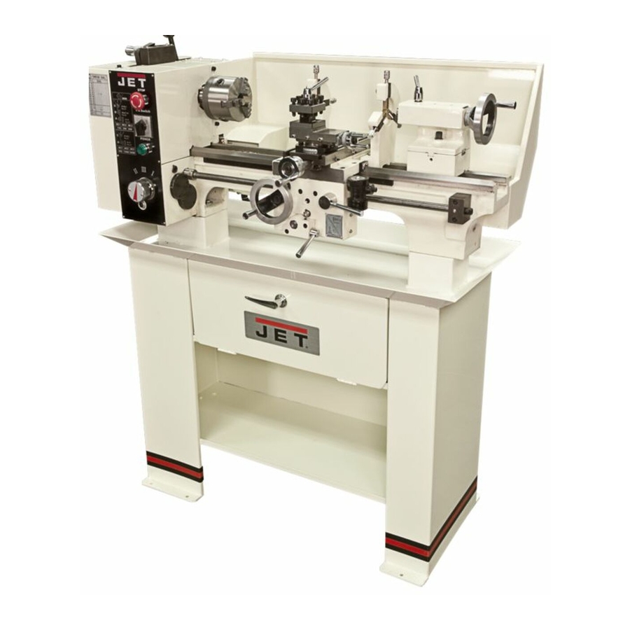
9 x 20-inch Belt Drive Bench Lathe
Model BD-920W
WALTER MEIER (Manufacturing) Inc.
427 New Sanford Road
LaVergne, Tennessee 37086
Part No. M-321376
Ph.: 800-274-6848
Revision H 01/2013
www.waltermeier.com
Copyright © 2013 Walter Meier (Manufacturing) Inc.
Advertisement
Table of Contents

Related Manuals for Jet BD-920W


Summary of Contents for Jet BD-920W
- Page 1 This .pdf document is bookmarked Operating Instructions and Parts Manual 9 x 20-inch Belt Drive Bench Lathe Model BD-920W WALTER MEIER (Manufacturing) Inc. 427 New Sanford Road LaVergne, Tennessee 37086 Part No. M-321376 Ph.: 800-274-6848 Revision H 01/2013 www.waltermeier.com Copyright © 2013 Walter Meier (Manufacturing) Inc.
-
Page 2: Warranty And Service
Walter Meier is consistently adding new products to the line. For complete, up-to-date product information, check with your local Walter Meier distributor, or visit www.jettools.com. WARRANTY JET products carry a limited warranty which varies in duration based upon the product (MW = Metalworking, WW = Woodworking). WHAT IS COVERED? This warranty covers any defects in workmanship or materials subject to the exceptions stated below. -
Page 3: Table Of Contents
Table of Contents Warranty and Service ............................2 Table of Contents ..............................3 Introduction ................................7 Specifications ................................ 7 Unpacking ................................8 Contents of the Shipping Container ...................... 8 Set Up and Preparation for Operation ........................9 ... - Page 4 A. GROUNDING INSTRUCTIONS 1. All grounded, cord-connected tools: In the event of a malfunction or breakdown, grounding provides a path of least resistance for electric current to reduce the risk of electric shock. This tool is equipped with an electric cord having an equipment-grounding conductor and a grounding plug.
- Page 5 B. FOR ALL TOOLS AS APPLICABLE 1. READ AND UNDERSTAND the warnings posted on the machine and in this manual. Failure to comply with all of these warnings may cause serious injury. 2. Replace the warning labels if they become obscured or removed. 3.
- Page 6 21. USE RECOMMENDED ACCESSORIES. Consult the owner's manual for recommended accessories. The use of improper accessories may cause risk of injury to persons. 22. NEVER STAND ON TOOL. Serious injury could occur if the tool is tipped or if the cutting tool is unintentionally contacted.
-
Page 7: Introduction
This manual is provided by Walter Meier (Manufacturing) Inc., covering the safe operation and maintenance procedures for a JET Model BD-920W Bench Lathe. This manual contains instructions on installation, safety precautions, general operating procedures, maintenance instructions and parts breakdown. This machine has been designed and constructed to provide years of trouble free operation if used in accordance with instructions set forth in this manual. -
Page 8: Unpacking
Unpacking Open shipping container and check for shipping damage; report any damage immediately to your distributor and shipping agent. Do not discard any shipping material until the Lathe is assembled and running properly. Compare the contents of your container with the following parts list to make sure all parts are intact. Missing parts, if any, should be reported to your distributor. -
Page 9: Set Up And Preparation For Operation
If stand mounted, the stand must be fastened to the floor. (An optional JET stand is available for this lathe – order stock no. 321374.) Remove rust protectant from all surfaces with kerosene, diesel oil, or a mild solvent. - Page 10 Carriage The carriage (Figure 5) is made from high-grade cast iron. The sliding parts are smooth ground. They fit the V on the bed without play. The lower sliding parts can be easily and simply adjusted. The cross slide is mounted on the carriage and moves on a dovetail.
- Page 11 Tailstock The tailstock (Figure 9) slides on a V-way and can be clamped at any location. The tailstock has a heavy duty spindle with a Morse taper No.2 socket and a graduated scale. The spindle can be clamped at any location with a clamping lever.
-
Page 12: Controls
Controls Figure 12 1. Forward/Reverse Switch 10. Tailstock Spindle Clamping Lever 2. V-Belt Tension Lever 11. Tailstock Locking Screw 3. Longitudinal Travel Handwheel 12. Tailstock Off-Set Adjustment 4. Half-Nut Lever 13. Automatic Feed Lever 5. Cross Slide Handwheel 14. Gear Box Quick Change Lever 6. -
Page 13: Operation
Operation Tool Set-Up The cutting angle is correct when the cutting edge is in line with the center axis of the work piece. The correct height of the tool can be achieved by comparing the tool point with the point of the center mounted in the tailstock. -
Page 14: Taper Turning Using Tailstock Off-Set
Taper Turning Using Tailstock Off-Set Offsetting the tailstock can turn work to side angle of 5º. The angle depends on the length of the workpiece. To off-set the tailstock, loosen locking screw (1, Figure 16) loosen the front adjusting screw (2) and take up the same amount by tightening the rear adjusting screw (3) until the desired taper has been reached. -
Page 15: Thread Cutting
Thread Cutting As indicated on the threading charts (see Figure 21), several different threads can be cut using the proper combination of gears and settings. When cutting inch threads, the half nut and threading dial (Figure 19) are used to thread in a conventional manner. -
Page 16: Lathe Accessories
Lathe Accessories Three Jaw Universal Lathe Chuck Using this universal chuck (Figure 22), round, triangular, square, hexagonal, octagonal, and twelve-cornered stock may be clamped. Note: new lathes have very tight fitting jaws. This is necessary to ensure accurate clamping and long service life. With repeated opening and closing, the jaws adjust automatically and their operation becomes progressively smoother. - Page 17 Steady Rest The steady rest (Figure 26) serves as a support for shafts on the free tailstock end. For many operations, the tailstock cannot be used as it obstructs the turning tool or drilling tool, and therefore, must be removed from the machine. The steady rest, which functions as an end support, ensures chatter-free operation.
-
Page 18: Adjustment And Replacement
Four‐way Tool Post The four-way tool post is mounted on the top slide and allows for tools to be clamped. Loosen the center clamp handle to rotate any of the four tools into position (Figure 29). Use a minimum of two clamping screws when installing a cutting tool. -
Page 19: Adjustment Of Compound Feed Screw And Float
Adjustment of Compound Feed Screw and Float To adjust the slides on the saddle: 1. Loosen screw (1, Figure 33) and lock nut (2, Figure 33). 18. Adjust the nut until all play has been taken up. Lock the nut (2) with the screw (1). Figure 33 Cross Slide Screw Remove the compound slide and adjust screw (1,... -
Page 20: Adjustment Of Half-Nut Guide
Adjustment of Half-Nut guide Loosen two nuts (1, Figure 36) on the right side of the apron and adjust the control screws (2, Figure 36) until both half nuts move freely without play. Tighten both nuts. Replacing the Shear Pin in the Leadscrew If the shear pin breaks, it must be replaced (Figure Figure 36... -
Page 21: Lubrication Schedule
Lubrication Schedule (Figures 40 and 41) Note: Lubricate all locations daily. Grease refers to #2 tube grease. Oil refers to 20W machine oil. 1 – 1 to 2 squirts of oil into oil ball on gear hub. 2 – Grease teeth of feed and change gears. 1 to 2 squirts of oil into oil ball on gear hub. -
Page 22: Replacement Parts
Replacement Parts Replacement parts are listed on the following pages. To order parts or reach our service department, call 1-800-274- 6848, Monday through Friday (see our website for business hours, www.waltermeier.com). Having the Model Number and Serial Number of your machine available when you call will allow us to serve you quickly and accurately. Headstock Assembly –... -
Page 23: Headstock Assembly - Parts List
Headstock Assembly – Parts List Index No. Part No. Description Size Qty 1 ....BD920N-1002 ..Headstock Casting ................1 2 ....1003 ......Cover ......................2 3 ....32007 ......Ball Bearing ................... 2 4 ....1005 ......Gasket ......................2 5 .... -
Page 24: Drive Assembly - Exploded View
Drive Assembly – Exploded View... -
Page 25: Drive Assembly - Parts List
Drive Assembly – Parts List Index No. Part No. Description Size Qty ....BD920N-3J.B.S..4-inch 3-Jaw Chuck (not shown) ..............1 ....BD920N-CJ3 ..... Chuck Jaw Set (set of 3; not shown) ............. 1 ....BD920N-ST ....Spanner Tool for Chuck (not shown) ............. 1 .... -
Page 26: Tension Roller Assembly - Exploded View & Parts List
Tension Roller Assembly – Exploded View & Parts List Index No. Part No. Description Size Qty 1 ....1040N......Washer ..............16mm ......1 3 ....1035A ......Swing Arm ..................... 1 4 .... -
Page 27: Quadrant Assembly - Exploded View & Parts List
Quadrant Assembly – Exploded View & Parts List Index No. Part No. Description Size Qty 1 ....2003A ......Bracket......................1 2 ....2004 ......T-Nut ......................1 3 .... -
Page 28: Electrical Assembly - Exploded View
Electrical Assembly – Exploded View... -
Page 29: Electrical Assembly - Parts List
Electrical Assembly – Parts List Index No. Part No. Description Size Qty 1 ....BD920N-E20 ..... EMG Switch ....................1 2 ....BD920N-E21 ..... Switch ......................1 3 ....BD920N-E22 ..... Indicator Light ....................1 4 ....TS-1531012 ....Phillips Pan Head Machine Screw ......M3x5 ......6 5 .... -
Page 30: Gear Box Assembly - Exploded View
Gear Box Assembly – Exploded View... -
Page 31: Gear Box Assembly - Parts List
Gear Box Assembly – Parts List Index No. Part No. Description Size Qty 1 ....TS-1522011 ....Set Screw ..............M5x6 ......1 2 ....BD920N-GB02 ..Bushing ......................1 3 ....BD920N-GB15 ..Snap Ring ..............16mm ......1 4 ....CQ6123B-3114 ..Gear ................. 27T ........ 1 5 .... -
Page 32: Apron Assembly - Exploded View
Apron Assembly – Exploded View... -
Page 33: Apron Assembly - Parts List
Apron Assembly – Parts List Index No. Part No. Description Size Qty 1 ....4006 ......Apron Casting ....................1 2 ....4004 ......Gear ................. 17T ........ 1 3 ....4011 ......Gear ................. 36T ........ 1 4 ....4009 ......Shaft ......................1 5 .... -
Page 34: Apron Assembly (Continued) - Exploded View
Apron Assembly (continued) – Exploded View... -
Page 35: Apron Assembly (Continued) - Parts List
Apron Assembly (continued) – Parts List Index No. Part No. Description Size Qty 35 ....TS-1540061 ....Hex Nut ..............M8 ......... 1 36 ....TS-1550061 ....Washer ..............8mm ......1 37 ....4029 ......Worm Gear .............. 64T ........ 1 38 .... -
Page 36: Saddle And Cross Slide - Exploded View
Saddle and Cross Slide – Exploded View... -
Page 37: Saddle And Cross Slide Assembly - Parts List
Saddle and Cross Slide Assembly – Parts List Index No. Part No. Description Size Qty 1 ....5005 ......Saddle......................1 2 ....5006 ......Cross Slide ....................1 3 ....5002 ......Gib ......................... 1 4 ....5036 ......Nut ......................... 1 5 .... -
Page 38: Top Slide Assembly - Exploded View
Top Slide Assembly – Exploded View... -
Page 39: Top Slide Assembly - Parts List
Top Slide Assembly – Parts List Index No. Part No. Description Size Qty ....BD920N-TSA .... Top Slide Assembly without Tool Post ............1 (index nos. 1-32, 36-38, 40, 41) ....BD920N-TP ....Four Way Tool Post, Complete (index nos. 35 and 39) ........1 1 .... -
Page 40: Tailstock Assembly - Exploded View
Tailstock Assembly – Exploded View... -
Page 41: Tailstock Assembly - Parts List
Tailstock Assembly – Parts List Index No. Part No. Description Size Qty 1 ....8009 ......Tailstock Ram ....................1 2 ....8008 ......Lever ......................1 3 ....BD920N-H ....Handle ......................1 4 ....8001 ......Clamp ......................1 5 .... -
Page 42: Steady Rest Assembly - Exploded View & Parts List
Steady Rest Assembly – Exploded View & Parts List Index No. Part No. Description Size Qty ....BD920N-SR ....Steady Rest Complete (index nos. 1-9) ............1 1 .... -
Page 43: Travel Rest Assembly - Exploded View & Parts List
Travel Rest Assembly – Exploded View & Parts List Index No. Part No. Description Size Qty ....BD920N-FR....Follow Rest Assembly (index nos. 1-9) ............1 1 .... -
Page 44: Lathe Bed Assembly - Exploded View
Lathe Bed Assembly – Exploded View... -
Page 45: Lathe Bed Assembly - Parts List
Lathe Bed Assembly – Parts List Index No. Part No. Description Size Qty 1 ....7001 ......Bed ........................ 1 2 ....7002 ......Rack....................... 1 3 ....TS-1501021 ....Socket Head Cap Screw.......... M4x8 ......6 4 ....7003 ......Leadscrew ............... 16TPI ......1 5 .... -
Page 46: Wiring Diagram
Wiring Diagram... - Page 47 This page intentionally left blank.
- Page 48 WALTER MEIER (Manufacturing) Inc. 427 New Sanford Road LaVergne, Tennessee 37086 Phone: 800-274-6848 www.jettools.com www.waltermeier.com...
Need help?
Do you have a question about the BD-920W and is the answer not in the manual?
Questions and answers