Carrier 42C Installation And Start-Up Instructions Manual
Ddc fan coil controller
Hide thumbs
Also See for 42C:
- Product data (140 pages) ,
- Installation instructions manual (100 pages) ,
- Installation, start-up and service instructions manual (82 pages)
Table of Contents
Advertisement
Quick Links
Installation and Start-Up Instructions
CONTENTS
SAFETY CONSIDERATIONS . . . . . . . . . . . . . . . . . . . . . . 1
GENERAL . . . . . . . . . . . . . . . . . . . . . . . . . . . . . . . . . . . . . . . . 1
INSTALLATION . . . . . . . . . . . . . . . . . . . . . . . . . . . . . . . . 1-17
General . . . . . . . . . . . . . . . . . . . . . . . . . . . . . . . . . . . . . . . . . . 1
Optional Field-Supplied Hardware. . . . . . . . . . . . . . . . 2
Control Power . . . . . . . . . . . . . . . . . . . . . . . . . . . . . . . . . . . . 2
Fan Coil Controller Inputs and Outputs . . . . . . . . . . 5
Install Sensors . . . . . . . . . . . . . . . . . . . . . . . . . . . . . . . . . . . 5
SENSOR INSTALLATION
INSTALLATION
INSTALLATION (Monitor Only)
INSTALLATION
Connect the Outputs . . . . . . . . . . . . . . . . . . . . . . . . . . . . 10
Connect Accessories . . . . . . . . . . . . . . . . . . . . . . . . . . . 13
Connect the CCN Communication Bus . . . . . . . . . . 13
START-UP . . . . . . . . . . . . . . . . . . . . . . . . . . . . . . . . . . . . 18,19
Perform System Check-Out . . . . . . . . . . . . . . . . . . . . . 18
Initial Operation and Test. . . . . . . . . . . . . . . . . . . . . . . . 18
DDC Fan Coil Control Testing Procedure . . . . . . . . 18
SAFETY CONSIDERATIONS
SAFETY NOTE
Air-handling equipment will provide safe and reliable
service when operated within design specifications. The
equipment should be operated and serviced only by
authorized personnel who have a thorough knowledge
of system operation, safety devices and emergency
procedures.
Good judgement should be used in applying any manu-
facturer's instructions to avoid injury to personnel or dam-
age to equipment and property.
Disconnect all power to the unit before performing mainte-
nance or service. Unit may automatically start if power is
not disconnected. Electrical shock and personal injury
could result.
Manufacturer reserves the right to discontinue, or change at any time, specifications or designs without notice and without incurring obligations.
PC 201
Book 3
Tab
7a
Page
) SENSOR
2
Catalog No. 534-231
Printed in U.S.A.
DDC Fan Coil Controller
42C,D,S,V Units
If it is necessary to remove and dispose of mercury contac-
tors in electric heat section, follow all local, state, and fed-
eral laws regarding disposal of equipment containing
hazardous materials.
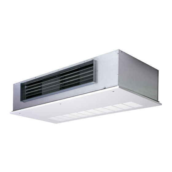
The DDC Fan Coil Controller is a factory-installed, CCN
(Carrier Comfort Network) communication control for fan coil
units. The fan coil controller is a microprocessor-based direct
digital control (DDC) controller for fan coil units. See Fig. 1.
The fan coil controller can function as either a stand-alone
control or as part of the CCN. User interfaces include the CCN
Network Service Tool, ComfortVIEW™, and Comfort-
®
WORKS
software. When used as part of the CCN, other de-
vices such as the CCN Data Transfer, Linkage Thermostat, or
Comfort Controller can read data from or write data to the fan
coil controller.
General -
The DDC fan coil controller can be connected
to a wall-mounted, field-supplied, space temperature sensor
(SPT) in order to monitor zone temperature changes and satisfy
zone demand. An optional factory-mounted return air sensor is
also available. See Fig. 2 and 3.
The following control options are available:
• heating only
• cooling only
• heating/cooling 2-pipe system with changeover
• heating/cooling 4-pipe system (available with 2-position
or modulating water valves)
• DX (direct expansion) cooling only
• DX cooling only and electric heat
On all heating or cooling applications, the fan coil controller
must be connected to a factory-installed supply-air temperature
(SAT) sensor to monitor the temperature of the air delivered by
the fan coil.
The following factory-installed sensor options are available:
• return-air sensor
• return-air sensor with T56 sensor (set point adjustment)
• return-air sensor with T57 fan coil thermostat (provides
set point adjustment and fan speed adjustment)
• changeover sensor
Carrier's Network Service Tool can be connected to the sys-
tem at the SPT sensor if CCN communication wiring is run to
an RJ-11 jack at the SPT sensor. The Network Service Tool can
be used to adjust set points, set operating parameters, and fully
configure the fan coil controller.
Form 42-1SI
GENERAL
INSTALLATION
Pg 1
12-00
Replaces: New
Advertisement
Table of Contents

Related Manuals for Carrier 42C


Summary of Contents for Carrier 42C
-
Page 1: Table Of Contents
Good judgement should be used in applying any manu- • changeover sensor facturer’s instructions to avoid injury to personnel or dam- Carrier’s Network Service Tool can be connected to the sys- age to equipment and property. tem at the SPT sensor if CCN communication wiring is run to an RJ-11 jack at the SPT sensor. -
Page 2: Installation
SOR — Each fan coil controller can support a field-supplied power transformer is supplied for each fan coil controller. Carrier space temperature sensor. There are three sensors avail- Transformers are UL (Underwriters’ Laboratories) Class 2 rat- able for this application: ed. -
Page 5: Fan Coil Controller Inputs And Outputs
Fan Coil Controller Inputs and Outputs — NOTE: When a wall-mounted space temperature sensor is The fan used, the return air sensor is disconnected by the installer. coil controller inputs and outputs are shown in Fig. 4-6. WALL-MOUNTED SPACE TEMPERATURE SENSOR Install Sensors —... - Page 6 Daughter Board Outputs (J6, J7) CHANNEL TERMINATIONS(+,–) DESCRIPTION CONTROL DEVICE FAN AC J6-1, J1-1 Fan Input Power 24V, 5A Fan Start/Stop FAN ON J6-2, J1-2 24V, 5A (Low Speed) J6-3, J1-2 Not Used 24V, 5A J6-4, J1-2 Med Speed 24V, 5A J6-5, J1-2 High Speed 24V, 5A...
- Page 7 Install the sensor as follows (see Fig. 8): terminal on the SEN terminal block (COM on 33ZCT57SPT). 1. Locate the two Allen type screws at the bottom of the sensor. d. Connect the remaining wire (WHITE/CLR) to the T56 terminal on the controller. Connect the other 2.
- Page 8 (33ZCT56SPT) WHITE (SPEED) 3-CONDUCTOR 3-CONDUCTOR SHIELDED CABLE SHIELDED CABLE LEGEND — Carrier Comfort Network — Switch Set Point — Set Point Adjust NOTES: 1. Do not connect white wire to SET termi- nal if set point adjustment is not needed.
- Page 9 Wiring when distance between fan coil controller and space temperature sensor is 50 feet or less 50 FT. MAXIMUM CCN COMM BUS 3 COND COMM CABLE (TYP) 2 COND TWISTED CABLE OR 3 COND CABLE (TEMP SENSOR WIRING) (TYP) FAN COIL ZONE CONTROLLER TYPICAL...
-
Page 10: Supply Air Temperature Sensor
The sensor must be mounted vertically on the wall. The (Monitor Only) — The indoor air quality (IAQ) sensor acces- Carrier logo should be oriented correctly when the sensor is sory monitors carbon dioxide levels. This information is used properly mounted. - Page 11 5.625 (14.3) (12.7) 3.25 0.25 1.125 (0.8) (8.3) (2.9) NOTE: Dimensions are in inches. Dimensions in ( ) are in centimeters. Fig. 12 — Indoor Air Quality (CO ) Sensor (33ZCSENCO2) (Monitor Only) 24 VAC LINE VOLTAGE SEPARATE POWER SUPPLY +24V DC REQUIRED +10V...
- Page 12 Fig. 14 — Wall Mounted Relative Humidity Sensor (P/N 33AMSENRHS000) HUMIDITY SENSOR WHITE BLACK Shield (If Used) +24V DC +10V FAN AC SPEED CNGOVR CONDSW REMOTE HIGH 24VAC Fresh Not Used Damper communications communications Valve Valve 24 VAC Line HEAT1 24VAC HEAT2 Voltage...
-
Page 13: Connect Accessories
At any baud (9600, 19200, 38400 baud), the number of con- SIGNAL TYPE COLOR NUMBER trollers is limited to 239 zones maximum. When Carrier link- age thermostats are used on the same bus as fan coil units, no Ground Green/White more than 128 fan coils and 12 linkage thermostats may be on –... - Page 14 Fig. 16 — Linkage Thermostat Wiring Connections (Field-Installed)
- Page 15 +24V DC 10 uf, 25VDC +10V FAN AC SPEED CNGOVR CONDSW REMOTE Use two conductor shielded cable HIGH 24VAC Fresh Not Used Damper communications communications Valve Valve HEAT1 24VAC HEAT2 24 VAC Line Voltage Equipment Ground NOTE: To ensure that the switch operates reliably in a low voltage circuit, install a field-supplied 10 µf, 25 VDC capacitor across the switch contacts.
- Page 16 POSITION DAMPER +24V DC +10V FAN AC SPEED CNGOVR CONDSW REMOTE HIGH 24VAC Fresh Not Used Damper communications communications Valve Valve 24 VAC Line HEAT1 24VAC HEAT2 Voltage Equipment Ground Fig. 18 — Two-Position, Minimum Outdoor Air Damper Wiring (Field-Installed)
- Page 17 BLK (TYP) WHT (TYP) RED (TYP) 1 2 3 1 2 3 1 2 3 1 2 3 1 2 3 COMM BRIDGE (RECOMMENDED) LEGEND CCN — Carrier Comfort Network FCC — Fan Coil Controller Fig. 20 — Communication Bus Wiring...
-
Page 18: Start-Up
TEMPERATURE SENSOR INPUT TEST — From the Points Display screen, verify the Space (Return Air) Temperature Use the Carrier network communication software to start up (RAT) and the Supply Air Temperature (SAT) are reading a and configure the fan coil controller. - Page 19 ELECTRIC HEAT TEST (Single-Stage Heat) 5. Move the slide bar adjustment on the sensor to the full right position. Verify on the display screen that the NOTE: This test should be performed with the unit power on temperature reset value changes to 2. and the supply fan running at high speed.
- Page 20 Copyright 2000 Carrier Corporation Manufacturer reserves the right to discontinue, or change at any time, specifications or designs without notice and without incurring obligations. Book 3 PC 201 Catalog No. 534-231 Printed in U.S.A. Form 42-1SI Pg 20 12-00 Replaces: New...
Need help?
Do you have a question about the 42C and is the answer not in the manual?
Questions and answers