Carrier 42C Series Product Data
Fan coil 50/60 hz 150 to 2000 cfm
Hide thumbs
Also See for 42C Series:
- Product data (140 pages) ,
- Installation instructions manual (100 pages) ,
- Installation, start-up and service instructions manual (82 pages)
Table of Contents
Advertisement
42SH STACK
Copyright 2004 Carrier Corporation
Product
Data
42CA HORIZONTAL
42DA DUCTED
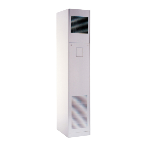
42VB VERTICAL
42C,D,S,V Series
Fan Coil
Air Conditioners
50/60 Hz
150 to 2000 cfm
Carrier's 42C,D,S,V Series fan-coil
units combine design flexibility with
easy, low-cost installation.
Features/Benefits
Versatility
If room fan coils are the answer to your
job requirements, choose from Carrier's
extensive range of superior fan-coil
units.
With Carrier's 42 series fan coils, you
can select from 5 horizontal, 6 vertical,
5 ducted or 3 stacked models; furred-in
or cabinet style, slant top or low silhou-
ette, in 150 through 2000 cfm capaci-
ties. Coils are available with 1, 2, 3, 4,
or 5 rows (depending on model), to
satisfy a variety of application require-
ments. The units are ideal for installa-
tion in motels, apartments, and other
multi-room buildings. Many optional
control packages are available, including
2-pipe heating and cooling, 2-pipe
heating and cooling with auxiliary elec-
tric heat, 2-pipe cooling with total elec-
tric heat, and 4-pipe heating and cool-
ing. Also offered are manual and auto-
matic changeover controls and several
thermostat options.
Casings and frame are fabricated from
tough, heavy gage galvanized steel. Op-
tional decorative colors allow the unit to
blend with any interior design.
Low-cost installation and
operation
Each unit is designed to occupy a
minimum space. No complex system
controls are required for Carrier fan coil
units. Piping, drain, and wiring connec-
tions are readily accessible and mount-
ing holes and slots are pre-drilled to
save installation time and field labor
expense.
Form 42-2PD
Advertisement
Table of Contents

Related Manuals for Carrier 42C Series


Summary of Contents for Carrier 42C Series
- Page 1 Carrier’s extensive range of superior fan-coil units. With Carrier’s 42 series fan coils, you can select from 5 horizontal, 6 vertical, 5 ducted or 3 stacked models; furred-in or cabinet style, slant top or low silhou- ette, in 150 through 2000 cfm capaci- ties.
-
Page 2: Table Of Contents
Guide Specifications — 42C Series ......105,106 heating and cooling performance Guide Specifications —... -
Page 3: Features/Benefits
Features/Benefits (cont) 42CF High-static, furred-in model. (400-1000 cfm) 42CA Furred-in ceiling model with low silhouette. (200-1200 cfm) 42CG Cabinet model for under-ceiling mount with bottom or rear stamped louver return air grille. (200-1200 cfm) 42CE Furred-in ceiling model with factory-installed plenum. - Page 4 Features/Benefits (cont) 42VC Furred-in loboy model for concealed under-the- 42VA window applications. (200-600 cfm) Furred-in model for under-the-window applications with top or front discharge. (200-1200 cfm) 42VE Cabinet loboy model with stamped louver dis- charge grille and 2 control access doors. (200-600 cfm) 42VB Cabinet model with top or...
- Page 5 42DD 42DA Vertical model with galvanized casing. Commonly for closet installation. Furred-in model for installation in the ceiling or over the closet. 42DE Ceiling model with galvanized casing. 42DC Furred-in ceiling model with factory-installed insulated plenum. 42DF Exposed-ceiling cabinet model with inte- gral double-deflection discharge grille and a bar-type return-air grille.
- Page 6 Features/Benefits (cont) 42SG — Furred-in-stack 42SJ — Back-to-back 42SH — Cabinet stack furred-in stack The furred-in-stack is a single unit, con- The back-to-back furred-in stack is The cabinet stack unit is designed for structed of 18-gage galvanized steel designed for installation in the separation applications where concealed installa- designed for concealed applications in wall between 2 separate rooms.
-
Page 7: Options And Accessories
42VA, 42VB, 42VF matically bleeding the system, and eliminating the need to • 4/1 High Capacity Same End Coil - 42C series, 42VA, manually remove air from the system. When wet, washers 42VB, 42VF swell and seal the system. - Page 8 Options and accessories (cont) Return-air grilles — Stamped-type return-air grilles are Trim strips — Strips are available for use with partially standard on 42C, V, S units. Anodized aluminum hinged recessed vertical 42VA units and 42S only. bar-type grilles are installed on 42CG, CK and DF (avail- Wall boxes —...
-
Page 9: Options And Accessories
• • • Filter and with or without Damper Damper, Linkage and Motor Wired to • • • Auxiliary Contact of 3-Speed Switch DECORATIVE COLORS (See Carrier Fan Coil Paint Selector • • • • • • • • •... -
Page 10: Controls
Controls Use the Control Selection guide to make sure that all NOTE: When thermostatic fan control is selected or when necessary components are provided for and that the com- unit outside air dampers are used, unit-mounted thermo- ponents are compatible with the required control system. stats are not recommended as their use will result in poor room temperature sensing. - Page 11 Remote-mounted controls Optional remote-mounted thermostat Line voltage T155 thermostat — Features 50 to 90 F temperature range, manual 3-speed fan control, mount is a standard 2 x 4 in. box, 4-pipe, 2-pipe and autochangeover applications. Available in vertical or horizontal styles. Unit-mounted controls Standard 3-speed switch —...
-
Page 12: Controls
Controls (cont) Four-pipe thermostat, model TH104 — With this Fan coil control relay board — The fan coil relay board thermostat, heating and cooling are sequenced (automatic is used in conjunction with the Debonair thermostat or a changeover) with 6 degree separation between HEATING CCN fan coil controller to regulate a single-speed or multi- ON and COOLING ON. -
Page 13: Application Data
Application data Basic definitions Opposite end connection (4-pipe option) — Hot water (HW) piping connections and electrical will be on the Unit hand — When facing the supply air outlet from the end (side) opposite the chilled water (CW) and drain front of the unit (air blowing in your face), your right hand connections. - Page 14 Application data (cont) System piping SYSTEM 2 — REVERSE RETURN The following diagrams show some common methods used to pipe the 42S series units. Only the 2-pipe systems are shown; however, the methods would be the same for 4-pipe systems. System 1, the “direct return”...
- Page 15 Risers Condensate drains are available in sizes down to one inch for greater first cost economy. Riser diameter is an important consideration in the design of stack series systems. Standard units can accommodate Riser size-reducers are factory installed and caps are pro- -in.
- Page 16 Application data (cont) PIPING COMPONENTS FACTOR RATING* STEAM SYMBOL/SKETCH DESCRIPTION MANUAL AIR VENT: Threaded brass needle valve with screwdriver slot for adjustment. Application — Body brazed into high point of heating and cooling coils for bleeding air from coil. Standard item on all hydronic coils (not used on steam or DX coils).
- Page 17 PIPING COMPONENTS (cont) FACTOR RATING STEAM SYMBOL/SKETCH DESCRIPTION PRESSURE TEST PORT: Brass body ser- vice access fitting with removable depressor type core. Application — Installed on both sides of the coil to allow for pressure sensing. Attach pressure gages to facilitate close tolerance water balancing.
- Page 18 Application data (cont) PIPING COMPONENTS (cont) FACTOR RATING STEAM SYMBOL/SKETCH DESCRIPTION STRAINER: Y-type body with 50 mesh stain- less steel screen. Application — Used for removal of small parti- cles from system water during normal system operation. Should not be used in lieu of main 19.0 system strainers.
- Page 19 PIPING COMPONENTS (cont) FACTOR RATING STEAM SYMBOL/SKETCH DESCRIPTION 2-WAY MOTORIZED VALVE: Electric 2-posi- tion flow control valve (open/closed). Normally closed body with manual override lever. Installed in supply line to unit. Application — All standard control and valve packages are based upon normally closed valves (valve electrically powered open and closed by spring return when electric power removed).
-
Page 20: Valve Packages
Application data (cont) Valve packages Valve packages are shipped with the units or in unit car- tons. Valve packages include belled ends for field soldering There are limitations on physical size of pneumatic valves, to coil connections. quantity and type of matching components, and required control interface. -
Page 21: Valve Package Arrangements
VALVE PACKAGE ARRANGEMENTS LEGEND Ball Valve Ball Valve with Memory Stop Gate Shut Off Valve Balancing Valve Circuit Setter Motorized 2-Way Valve Motorized 3-Way Valve *When aquastat is used for automatic changeover, bypass is required as indicated by dashed line. NOTES: 1. - Page 22 Application data (cont) Cv FACTOR VS WATER PRESSURE DROP FACTOR: The flow rate in gallons per minute (gpm) through a piping component when the pressure drop (∆P) in pounds per square inch (psi) across the component is 1.0 (psi). Pressure drop (ft-H O) = 2.31 x psi (pressure drop) GRAPH EXAMPLE: ∆P for 2.0 gpm through a component with a C...
- Page 23 ENTHALPY AT SATURATION ENTHALPY AT ENTHALPY AT TEMPERATURE SATURATION TEMPERATURE SATURATION (Btu per lb. (Btu per lb of dry air) of dry air) 15.230 26.46 15.697 27.15 16.172 27.85 16.657 28.57 17.149 29.31 17.650 30.06 18.161 30.83 18.680 31.62 19.211 32.42 19.751 33.25...
- Page 24 42S stack units, the strip heater is located in the fan dis- charge on the leaving side of the coil. Electric heaters are available for installation on Carrier fan coil units in the following applications. Sheath heaters are used with Model 42V vertical units.
- Page 25 UNIT SIZE HEATER CAPACITY VOLTAGE VOLTAGE (Btuh) 1,708 3,415 5,123 6,830 10,245 3,415 5,123 208, 6,830 240, 10,245 13,660 17,075 240,277 20,490 NOTE: All heaters are single-stage and single-phase. Contact your Carrier representative for heater availability for 220-1-50 units. 240, 10.0...
-
Page 26: Selection Procedure
Selection procedure Refer to the Carrier Electronic Selection Program for infor- 3. Select the actual cfm from the Air Delivery table on mation to determine unit sizing for your needs. The follow- page 82. ing selection procedure applies to all Carrier 42 series... -
Page 27: Model Number Nomenclature
Model number nomenclature – – – – 42 – Series Fan-Coil Unit Arrangement 42V: 5 – Front Return, Top Supply Model 7 – Front Return, Front Supply Vertical Units 42C: VA – Furred-In 5 – Bottom Return, Front Supply VB – Cabinet 6 –... -
Page 28: Ari Capacity Ratings
ARI capacity ratings The 42C, V series fan coil units are certified in compliance with the Air Conditioning and Refrigeration Institute (ARI) Industry Standard 440-98 for room fan coil units. Ap- proved standard ratings are tabulated below: ARI APPROVED STANDARD RATINGS* COOLING CAPACITY UNIT COIL... -
Page 29: Sound Data
Sound data SOUND POWER DATA 42CA,CG,CE,CK SOUND RATINGS — OCTAVE BAND POWER LEVEL RATINGS* (dB) CENTER FREQUENCY — Hz NOMINAL SIZE SPEED 1000 2000 4000 8000 High 1130 Medium 1060 High 1125 Medium 1025 High 1400 Medium — — High 1525 Medium 1100... -
Page 30: Sound Data
Sound data (cont) SOUND POWER DATA 42VA,VB,VF SOUND RATINGS — OCTAVE BAND SOUND POWER LEVEL RATINGS* (dB) CENTER FREQUENCY — Hz NOMINAL SIZE SPEED 1000 2000 4000 8000 High 1130 Medium 1090 — 1025 — High 1120 Medium 1070 — 1000 —... -
Page 31: Physical Data And Dimensions
— — 1.02 1.42 1.71 2.32 — COILS 10 fins/inch Coil Face Area (sq. ft)† MOTOR (qty) 42C Series BLOWER (qty) 42CA, CE, CG, CK 42CF — — — FILTERS Nominal Size (in.) (1-in. thick) 42CA** 10 x 24 10 x 28... - Page 32 Physical data and dimensions (cont) 42CA FURRED-IN HORIZONTAL UNIT NOTES: LEGEND 1. Right hand unit shown; left hand unit opposite. Coil connection loca- 1 — Flexible Metal Conduit tions are ± -in. 2 — Air Vent, -in. MPT 2. Unit sizes 02 and 03 have one motor, one blower; sizes 04 through 3 —...
- Page 33 42CE FURRED-IN HORIZONTAL UNIT WITH PLENUM LEGEND NOTES: 1. Right hand unit with standard 3-row coil shown; left hand unit opposite. Coil — Flexible Metal Conduit connection locations are ± -in. — Junction Box, 4 in. x 4 in. 2. Unit sizes 02 and 03 have one motor, one blower; sizes 04 through 08 have —...
- Page 34 Physical data and dimensions (cont) 42CF FURRED-IN HIGH-STATIC HORIZONTAL UNIT WITH PLENUM NOTES: LEGEND 1. Right hand unit shown; left hand unit opposite. Coil connection — Flexible Metal Conduit locations are ± -in. — Junction Box, Installed with Plenum 2. Unit sizes 04 thru 08 have one motor, 2 blowers; size 10 has —...
- Page 35 42CG HORIZONTAL CABINET UNIT NOTES: LEGEND 1. Right hand unit shown; left hand unit opposite. Coil connection — Junction Box, 4 in. x 4 in. locations are ± -in. — Mounting Holes (4), Rubber Grommets 2. Unit sizes 02 and 03 have one motor, one blower; sizes 04 through have -in.
- Page 36 Physical data and dimensions (cont) 42CK HORIZONTAL CABINET UNIT WITH TELESCOPING ACCESS PANEL LEGEND NOTES: 1. Right hand unit shown; left hand unit opposite. Coil connection — Duct Collar, Telescoping locations are ± -in. — Mounting Holes (4), Rubber Grommets 2.
- Page 37 42VA FURRED-IN VERTICAL UNIT LEGEND NOTES: 1. Right hand unit shown; left hand unit opposite. Coil connection — Wall Mounting Holes (4), -in. Diameter locations are ± -in. — Drain Pan, Auxiliary, Shipped Loose 2. Unit sizes 02 and 03 have one motor, one blower; sizes 04 through —...
- Page 38 Physical data and dimensions (cont) 42VB VERTICAL CABINET UNIT LEGEND NOTES: 1. Right hand unit shown; left hand unit opposite. Coil connection — Access Door, Fan Switch locations are ± -in. — Electrical KO 2. Unit sizes 02 and 03 have one motor, one blower; sizes 04 through —...
- Page 39 42VF VERTICAL CABINET UNIT WITH SLANT TOP LEGEND NOTES: 1. Right hand unit shown; left hand unit opposite. Coil connection — Fan Switch, 3 speed locations are ± -in. — Wall Mounting Holes -in. Diameter 2. Unit sizes 02 and 03 have one motor, one blower; sizes 04 through —...
- Page 40 Physical data and dimensions (cont) 42VC FURRED-IN LOBOY UNIT LEGEND NOTES: 1. Right hand unit shown; left hand unit opposite. Coil connection — Discharge Opening locations are ± -in. — Junction Box, 4 in. x 4 in. 2. Unit sizes 02 through 04 have one motor, 2 blowers; size 06 has —...
- Page 41 42VE CABINET LOBOY UNIT LEGEND NOTES: 1. Right hand unit shown; left hand unit opposite. Coil connection — Fan Switch, 3-Speed, behind Access Door locations are ± -in. — Stamped Supply Grille 2. Unit sizes 02 through 04 have one motor, 2 blowers; size 06 has —...
-
Page 42: Physical Data And Dimensions
Physical data and dimensions (cont) 42VG FURRED-IN WALL UNIT LEGEND NOTES: 1. Right hand unit shown; left hand unit opposite. Coil connection — Electrical KO, -in. Diameter locations are ± -in. — Stamped Supply Grille 2. Front panel has an Arctic White baked finish. —... -
Page 43: Accessory Dimensions
Accessory dimensions OUTSIDE AIR OPENING/DAMPER NOMINAL UNIT DIM. A AIRFLOW SIZE (in.) (CFM) 1000 1200 NOTE: A 6-in. diameter outside air opening with duct collar and filter is available for 42CE,CF,CG,CK,VA,VB, and VF units. It is also available with a round damper. -
Page 44: Accessory Dimensions
Accessory dimensions (cont) - Page 46 Accessory dimensions (cont) 42VC,VE OPTIONAL COIL CONNECTION LOCATION SIZE 02 THRU 06 NOTES: 1. Dimensions for split coils with opposite end connections will vary. 2. Coil connection diemsnions are for coils stub outs only (valve packages not included). 3. All dimensions are in inches. COIL CONNECTION DIMENSIONS 23-ROW COIL 3-ROW COIL...
- Page 47 DECORATIVE WALL PANELS (42VA units only) WALL OPENING DIM UNIT SIZE CFM A (in.) B (in.) WALL OPENING DIM 1/2” 1/2” 1/2” 1/2” Front Return Front Return and Supply Top Supply with Access Doors 25” 30” 1000 1200 1/2” 1/2” 1/2”...
-
Page 48: Performance Data
Performance data 42CA,CE,CF,CG,CK,VA,VB,VF COOLING CAPACITY (by GPM) 3-ROW COIL 75 F DB/63 F WB 80 F DB/67 F WB 85 F DB/71 F WB UNIT 40 F EWT 45 F EWT 50 F EWT 40 F EWT 45 F EWT 50 F EWT 40 F EWT 45 F EWT... - Page 49 42CA,CE,CF,CG,CK,VA,VB,VF COOLING CAPACITY (by ∆T) 3-ROW COIL 75 F DB/63 F WB 80 F DB/67 F WB 85 F DB/71 F WB UNIT ∆T 40 F EWT 45 F EWT 50 F EWT 40 F EWT 45 F EWT 50 F EWT 40 F EWT 45 F EWT 50 F EWT...
-
Page 50: Performance Data
Performance data (cont) 42VC,VE,VG COOLING CAPACITY (by GPM) 2-ROW COIL 75 F DB/63 F WB 80 F DB/67 F WB 85 F DB/71 F WB UNIT 40 F EWT 45 F EWT 50 F EWT 40 F EWT 45 F EWT 50 F EWT 40 F EWT 45 F EWT... - Page 51 42VC,VE,VG COOLING CAPACITY (by ∆T) 2-ROW COIL 75 F DB/63 F WB 80 F DB/67 F WB 85 F DB/71 F WB UNIT ∆T 40 F EWT 45 F EWT 50 F EWT 40 F EWT 45 F EWT 50 F EWT 40 F EWT 45 F EWT 50 F EWT...
- Page 52 Performance data (cont) AIR DELIVERY (CFM) 42CA — 60 Hz MOTOR EXTERNAL STATIC PRESSURE (in. wg) UNIT COIL SIZE ROWS SPEED 0.00 0.05 0.10 0.15 0.20 0.25 0.30 High — — — — — — — — — — — —...
- Page 53 AIR DELIVERY (CFM) (cont) 42CA — 60 Hz MOTOR (cont) EXTERNAL STATIC PRESSURE (in. wg) UNIT COIL SIZE ROWS SPEED 0.00 0.05 0.10 0.15 0.20 0.25 0.30 High — — — — — — — — High — — — —...
- Page 54 Performance data (cont) AIR DELIVERY (CFM) (cont) 42CE,CG,CK — 60 Hz MOTOR EXTERNAL STATIC PRESSURE (in. wg) UNIT COIL SIZE ROWS SPEED 0.00 0.05 0.10 0.15 0.20 0.25 0.30 High — — — — — — — — — — —...
- Page 55 AIR DELIVERY (CFM) (cont) 42CE,CG,CK — 60 Hz MOTOR (cont) EXTERNAL STATIC PRESSURE (in. wg) UNIT COIL SIZE ROWS SPEED 0.00 0.05 0.10 0.15 0.20 0.25 0.30 High — — — — — — — — High — — — —...
- Page 56 Performance data (cont) AIR DELIVERY (CFM) (cont) 42CF — 60 Hz MOTOR EXTERNAL STATIC PRESSURE (in. wg) UNIT COIL SIZE ROWS SPEED 0.00 0.05 0.10 0.15 0.20 0.25 0.30 High — — — — — — High — — — —...
- Page 57 AIR DELIVERY (CFM) (cont) 42VA,VB,VF — 60 Hz MOTOR EXTERNAL STATIC PRESSURE (in. wg) UNIT COIL SIZE ROWS SPEED 0.00 0.05 0.10 0.15 0.20 0.25 0.30 High — — — — — — — — — — — — High —...
- Page 58 Performance data (cont) AIR DELIVERY (CFM) (cont) 42VA,VB,VF — 60 Hz MOTOR (cont) EXTERNAL STATIC PRESSURE (in. wg) UNIT COIL SIZE ROWS SPEED 0.00 0.05 0.10 0.15 0.20 0.25 0.30 High — — — — — — — — — High —...
- Page 59 AIR DELIVERY (CFM) (cont) 42VC,VE — 60 Hz MOTOR EXTERNAL STATIC PRESSURE (in. wg) UNIT COIL SIZE ROWS SPEED 0.00 0.05 0.10 0.15 0.20 0.25 0.30 High — — — — — — — — — — — High — —...
- Page 60 Performance data (cont) COOLING CAPACITY CORRECTION FACTORS UNIT SIZE ACTUAL AIRFLOW (Cfm) 0.62 0.57 — — — — — — — — — — — — 0.72 0.69 0.54 0.48 0.44 0.39 — — — — — — — — 0.82 0.80 0.62...
- Page 61 DIRECT-EXPANSION (DX) COIL COOLING CAPACITIES (MBtuh)* — MODELS 42VA,VB,VF 3 ROW 4 ROW Entering Air (F) — db/wb UNIT SUCT SIZE TEMP 76/63 78/65 80/67 82/69 76/63 78/65 80/67 82/69 10.1 11.1 10.7 11.8 12.9 11.6 12.8 14.0 15.3 11.0 10.8 12.0 13.3...
- Page 62 Performance data (cont) HOT WATER HEATING CAPACITIES (MBtuh)* — MODELS 42CA,CE,CF,CG,CK,VA,VB,VF WATER FLOW (GPM) UNIT ROWS SIZE 10.0 12.0 — — — — — — 11.2 12.0 12.5 12.8 13.0 — — — — — — 12.0 14.0 15.3 16.2 16.8 17.1 —...
- Page 63 COOLING AND HEATING CAPACITIES (Btuh) — MODEL 42VG COOLING HEATING PRESSURE UNIT AIRFLOW WATER FLOW DROP Entering Water Temperature (F) SIZE (Cfm) (Gpm) (ft. wg) 4,240 3,450 2,750 8,200 10,000 4,950 4,080 3,270 8,750 10,850 5,320 4,500 3,500 9,220 11,300 5,500 4,620 3,620...
-
Page 64: Electrical Data
FLA — Full Load Amps NOTE: All heaters are single-stage and single-phase. UL Listing The UL Listing signifies that Carrier’s fan coil units have been examined by UL and comply with the organization’s applicable standards. The Canadian Standards Association (CSA) and Underwriters’ Laboratories of Canada also approve the fan coil units. - Page 65 42CF MOTOR DATA UNIT SIZE VOLTS-PH-Hz SPEED SPEED Nominal Nominal Nominal Nominal (RPM) Watts Amps Watts Amps Watts Amps Watts Amps 1200 1.40 0.83 1.70 2.80 115-1-60 1.65 1.70 1.70 3.37 1.45 1.65 1.45 2.95 1200 0.68 1.45 0.74 1.44 208-1-60 0.60 0.72...
- Page 66 Electrical data (cont) 42VC,VE MOTOR DATA UNIT SIZE VOLTS-PH-Hz SPEED SPEED Nominal Nominal Nominal (RPM) Watts Amps Watts Amps Watts Amps 1200 0.34 1.35 1.45 115-1-60 0.30 0.60 0.60 0.20 0.30 0.30 1200 0.46 0.56 0.60 208-1-60 0.20 0.30 0.30 1200 0.50 0.60...
-
Page 67: Model Number Nomenclature
Model number nomenclature 06 B – – – – – Arrangement 42DA, DC, DE, DF 42DD 42D Series – Ducted Fan Coil Unit Return Supply Return Supply 5 – Bottom Front Front Model 6 – Rear Front Bottom A – Furred-in ceiling model C –... -
Page 68: Sound Data
Sound data SOUND POWER DATA 42D SOUND RATINGS — OCTAVE BAND SOUND POWER LEVEL RATINGS* (dB) CENTER FREQUENCY — Hz NOMINAL SIZE SPEED 1000 2000 4000 8000 High 68.5 55.5 42.5 34.5 Medium 64.5 60.5 51.5 48.5 40.5 35.5 — 50.5 —... - Page 69 Physical data and dimensions (cont) 42DA FURRED-IN CEILING MODEL LEGEND DIMENSIONS (in. ± UNIT 1 — Motor-Blower Assembly SIZE 2 — Motor Junction Box 3 — Auxiliary Drip Lip (Optional, Shipped Loose) 4 — Supply Duct Collar, 1 inch 5 — Mounting Holes (four, -in.
- Page 70 Physical data and dimensions (cont) 42DC FURRED-IN CEILING MODEL WITH PLENUM LEGEND DIMENSIONS (in. ± UNIT 1 — Mounting Clips (Shipped Loose) SIZE 2 — Motor Junction Box Opposite Piping 3 — Insulated Return Air Plenum Mounting Holes (four, -in. diameter) 4 —...
- Page 71 9. For bottom return (required for optional slide-in filter service from front) use dimen- sion B minus 3 in. 10. Consult Carrier for ducted front return air and external filter rack with 1-in. duct col- lar and throwaway filters. 11. Units with electric heat require additional access on the side of unit for servicing...
- Page 72 Physical data and dimensions (cont) 42DE CEILING MODEL WITH FULL CASING LEGEND DIMENSIONS (in. ± UNIT 1 — Insulation, -in. Thick Fiberglass SIZE 2 — Coil, 4-row 3 — Unit Mounting Channel (2), 14-gage; 4 Mounting Slots, -in. x 2-in. 4 —...
- Page 73 42DF EXPOSED CEILING CABINET MODEL WITH SUPPLY AND RETURN AIR GRILLES LEGEND 1 — Coil, 4-row 2 — Insulation, -in. Thick Fiberglass 3 — Junction Box 4 — Filter, Throwaway 5 — Unit Mounting Channel (2), 14-gage; 4 Mounting Slots, in.
-
Page 74: Accessory Dimensions
Accessory dimensions... - Page 76 49 x 13 2000 54 x 14 48 x 14 53 x 13 NOTES: 1. Refer to Physical Data pages for actual return opening dimensions. Field-furnished duct transitions may be required. 2. For return air grille filter sizes, contact Carrier.
-
Page 77: Performance Data
Performance data 42D COOLING CAPACITY (by GPM) 3-ROW COIL 75 F DB/63 F WB 80 F DB/67 F WB 85 F DB/71 F WB UNIT 40 F EWT 45 F EWT 50 F EWT 40 F EWT 45 F EWT 50 F EWT 40 F EWT 45 F EWT... - Page 78 Performance data (cont) 42D COOLING CAPACITY (by GPM) 6-ROW COIL 75 F DB/63 F WB 80 F DB/67 F WB 85 F DB/71 F WB UNIT 40 F EWT 45 F EWT 50 F EWT 40 F EWT 45 F EWT 50 F EWT 40 F EWT 45 F EWT...
- Page 79 42D COOLING CAPACITY (by ∆T) 3-ROW COIL 75 F DB/63 F WB 80 F DB/67 F WB 85 F DB/71 F WB UNIT ∆T 40 F EWT 45 F EWT 50 F EWT 40°F EWT 45 F EWT 50 F EWT 40 F EWT 45 F EWT 50 F EWT...
- Page 80 Performance data (cont) 42D COOLING CAPACITY (by ∆T) 6-ROW COIL 75 F DB/63 F WB 80 F DB/67 F WB 85 F DB/71 F WB UNIT SIZE ∆T 40 F EWT 45 F EWT 50 F EWT 40 F EWT 45 F EWT 50 F EWT 40 F EWT...
- Page 81 AIR DELIVERY (CFM) — 60 Hz MOTOR 42DA EXTERNAL STATIC PRESSURE (in. wg) UNIT ROWS SIZE SPEED 0.05 0.10 0.15 0.20 0.25 0.30 0.40 0.50 0.60 HIGH — — — — — — — — — — HIGH — — —...
- Page 82 Performance data (cont) AIR DELIVERY (CFM) — 60 Hz MOTOR (cont) 42DC,DD, AND DE EXTERNAL STATIC PRESSURE (in. wg) UNIT ROWS SIZE SPEED 0.05 0.10 0.15 0.20 0.25 0.30 0.40 0.50 0.60 HIGH — — — — — — — —...
- Page 83 AIR DELIVERY (CFM) — 60 Hz MOTOR (cont) 42DF EXTERNAL STATIC PRESSURE (in. wg) UNIT ROWS SIZE SPEED 0.05 0.10 0.15 0.20 0.25 HIGH — — — — — HIGH — — — — — — — HIGH — — —...
- Page 84 Performance data (cont) 42D SERIES COOLING CAPACITY CORRECTION FACTORS UNIT SIZE ACTUAL — — — — — — — — — — — — — — — — — — — — — — — — — — — — —...
- Page 85 DIRECT-EXPANSION (DX) COIL COOLING CAPACITIES* (MBtuh) 4 ROW 6 ROW SAT. Entering Air Temperature (F) — db/wb UNIT SUCT SIZE TEMP 76/63 78/65 80/67 82/69 76/63 78/65 80/67 82/69 21.0 15.8 23.1 16.4 25.3 17.0 27.5 17.5 26.0 18.9 23.3 19.5 30.8 20.0...
-
Page 86: Performance Data
Performance data (cont) 42D HOT WATER HEATING CAPACITIES (MBtuh) UNIT ROWS SIZE 10.0 11.0 13.5 17.5 19.5 20.5 21.3 21.8 22.2 22.5 — — — — — — — 16.0 22.0 24.6 26.5 27.9 29.0 29.5 29.9 — — — —... -
Page 87: Electrical Data
Power supply circuit to unit must be field furnished and installed in accordance with applicable codes. UL Listing The UL Listing signifies that Carrier’s fan coil units have been examined by UL and comply with the organization’s applicable standards. The Canadian Standards Association (CSA) and Underwriters’... -
Page 88: Electrical Data
Electrical data (cont) 42DA MOTOR DATA UNIT SIZE VOLTS/PH-Hz SPEED SPEED (RPM) Nominal Nominal Nominal Nominal Watts Amps Watts Amps Watts Amps Watts Amps 1200 2.70 3.10 5.60 5.30 115-1-60 2.00 2.25 3.70 2.92 1.50 1.44 2.60 1.93 1200 1.10 1.80 2.00 2.10... - Page 89 42DF MOTOR DATA UNIT SIZE VOLTS/PH-Hz SPEED SPEED Nominal Nominal Nominal Nominal (RPM) Watts Amps Watts Amps Watts Amps Watts Amps 1200 2.40 3.10 3.70 4.40 115-1-60 1.70 2.10 3.00 3.00 1.15 1.58 2.00 2.10 1200 1.00 1.05 1.80 2.00 208/230-1-60 0.72 0.65...
-
Page 90: 42S
Model number nomenclature 42S G A 06 - Size (cfm) 42S - Vertical Stack Unit 03 - 04 - 06 - 08 - 10 - 1000 12 - 1200 Model G - Furred-In Single H - Cabinet J - Furred-In Back-to-Back Series ARI capacity ratings The 42S series fan coil units are certified in compliance... -
Page 91: Sound Data
Sound data SOUND PRESSURE DATA 42S SOUND RATINGS — OCTAVE BAND SOUND POWER LEVEL RATINGS* (db) CENTER FREQUENCY — Hz NOMINAL SIZE SPEED 1000 2000 4000 8000 High 1075 64.5 52.5 35.5 Medium 61.5 51.5 48.5 43.5 33.5 30.5 24.5 45.5 42.5 35.5... - Page 92 Physical data and dimensions (cont) 42SG FURRED-IN STACK 42SGA 4–PIPE OPTION NOTES: 1. Units are fabricated of 18-gage galvanized steel with a 16-gage galvanized fan deck. TOP VIEW 2. All risers are insulated with -in. closed cell insulation. 3. Thermostats shipped loose for field connection. 4.
- Page 93 42SH CABINET CR CS 42SHA 4–PIPE OPTIONS NOTES: TOP VIEW 1. Units are fabricated of 18-gage galvanized steel with a 16-gage galvanized fan deck, painted with Arctic White. 2. 3 speed switch and thermostat are unit mounted. 3. Risers are piped to coil with valves as specified.
-
Page 94: Physical Data And Dimensions
Physical data and dimensions (cont) 42SJ BACK-TO-BACK FURRED-IN STACK NOTES: 1. Units are fabricated of 18-gage galva- ‘A’ nized steel with a 16-gage galvanized fan deck. SIDE ‘A’ ‘B’ 2. All risers are insulated with -in. 4–PIPE SIDE SIDE closed cell insulation. 3. -
Page 95: Accessory Dimensions
Accessory dimensions PANEL NO. 1 PANEL NO. 2 SHORT FRAME — SURFACE MOUNTED GRILLE LONG FRAME — SURFACE MOUNTED GRILLE PANEL NO. 3 GRILLE LOCATIONS UNIT FIG. GRILLE ARRANGEMENTS Up to 3 grilles located on any of Supply 3 sides shown. 42SG One grille located on any of 3 sides Return... -
Page 96: Accessory Dimensions
Accessory dimensions (cont) PANEL NO. 4 PANEL NO. 5 SHORT FRAME — FLUSH MOUNTED GRILLE LONG FRAME — FLUSH MOUNTED GRILLE... - Page 97 RETURN-AIR WALL PANELS FOR FURRED-IN UNITS Panel and Frame Dimensions (in.) PANEL UNIT SIZE 03, 04 — 06, 08 — 10, 12 — 03, 04 — 06, 08 — 10, 12 — 03, 04 — — — 06, 08 — —...
-
Page 98: Performance Data
Performance data AIR DELIVERY CFM AT 0.0 ESP FOR FAN SPEED HIGH SPEED CFM AT ESP INDICATED UNIT SIZE COIL High 0.05 0.10 0.15 0.20 0.25 3 Row 1130 1100 1070 1040 1000 1260 1230 1200 1160 1130 1090 42SG,SH,SJ 4 Row 1090 1060... - Page 99 42S COOLING CAPACITY (GPM) 3-ROW COIL 75 F DB/63 F WB 80 F DB/67 F WB 85 F DB/71 F WB UNIT 40 F EWT 45 F EWT 50 F EWT 40 F EWT 45 F EWT 50 F EWT 40 F EWT 45 F EWT 50 F EWT...
-
Page 100: Performance Data
Performance data (cont) 42S COOLING CAPACITY (∆T) 3-ROW COIL 75 F DB/63 F WB 80 F DB/67 F WB 85 F DB/71 F WB UNIT ∆T 40 F EWT 45 F EWT 50 F EWT 40 F EWT 45 F EWT 50 F EWT 40 F EWT 45 F EWT... - Page 101 42S COOLING CAPACITY CORRECTION FACTORS UNIT SIZE ACTUAL — — — — — — — — — — — — 0.54 0.48 0.44 0.39 — — — — — — — — 0.62 0.57 0.51 0.45 — — — — —...
- Page 102 Performance data (cont) 42S HOT WATER HEATING CAPACITIES (MBtuh) ROWS UNIT SIZE 14.7 15.7 16.4 — — — 15.5 18.4 19.2 — — — — 15.7 23.3 25.3 26.2 — — 1 ROW — 16.6 25.7 28.2 29.0 — — —...
- Page 103 MAIN RISER PRESSURE DROPS...
-
Page 104: Electrical Data
Power supply circuit to unit must be field furnished and installed in accordance with applicable codes. UL Listing The UL Listing signifies that Carrier's fan coil units have been examined by UL and comply with the organization's applicable standards. The Canadian Standards Association (CSA) and Underwriters' Laboratories of Canada also approve the fan coil units. -
Page 105: Guide Specifications - 42C Series
Guide specifications — 42C series with ½-in. fiberglass Tuf-Skin II insulation. Unit shall Fan Coil Unit — Horizontal Models have a removable panel to provide access to fan/ HVAC Guide Specifications — 42C motor assemblies and unit identification label. Size Range: 200 to 1200 Nominal Cfm D. -
Page 106: Guide Specifications — 42C Series
Guide specifications — 42C series (cont) type bearings and oversized oil reservoirs to ensure act as an indicator that the main drain is lubrication. plugged. L. Special Features: 9. A hinged, bar type aluminum return-air grille with filter holder shall be furnished for field Certain standard features are not applicable when installation (42CA, CE, CF). -
Page 107: Guide Specifications - 42D Series
HVAC Guide Specifications — 42D D. Horizontal, Enclosed Unit for Concealed Installation Size Range: 600 to 2000 Nominal Cfm (42DE): Carrier Model Numbers: Unit shall be constructed of galvanized steel with 42DA (Ceiling Furred-in) removable panels for access to internal compo- 42DC (Ceiling Furred-in with Plenum) nents. -
Page 108: Guide Specifications — 42D Series
8. Drain pan shall include a second drain connec- the features designated by * are specified. See tion located above the main drain connection to your local Carrier Sales Office for amending act as an indicator that the main drain is specifications. -
Page 109: Guide Specifications - 42S Series
18-gage galvanized steel back Size Range: 300 to 1200 Nominal Cfm panel. These units are similar to the 42SG but are Carrier Model Numbers: actually two completely separate units contained in 42SGA (Furred-in) one cabinet that share a common set of risers. -
Page 110: Guide Specifications — 42S Series
Guide specifications — 42S series (cont) I. Risers: * 3. For installation in a 4-pipe system, unit shall be equipped with: 1. Standard factory-furnished and installed risers shall be 104 in. long with 3-in. belled ends at a. A 3/1, 3/2 or 4/1 row-split coil, as shown the top such that only one sweat connection on equipment drawings for cooling and shall be required at each floor to join one riser... - Page 111 *d. For total electric heat, unit controls shall 18. Fused or unfused disconnect switch shall be include a sequenced heating and cooling provided for field installation. Switch shall be thermostat in lieu of the heating/cooling suitable for single phase, 60 Hz service for 115, thermostat automatic changeover...
-
Page 112: Guide Specifications - 42V Series
Size Range: 200 to 1200 Nominal Cfm cabinet height shall not exceed 14 in. on low profile 42VE unit.) Carrier Model Numbers: 42VA (Furred-in) 3. The 42VF top panel shall slope down from 42VB (Cabinet) back to front at an angle of 25 degrees. Stan-... - Page 113 (Not available for VG unit.) the features designated by * are specified. See 14. Manual stop, gate, balancing, combination bal- your local Carrier Sales Office for amending ance and stop (ball type), and flow control specifications. valves shall be factory furnished and installed as * 1.
- Page 114 Electric heaters Selection procedure 10, 24, 25, 64, 87, 104 Carrier Corporation • Syracuse, New York 13221 2-04 Manufacturer reserves the right to discontinue, or change at any time, specifications or designs without notice and without incurring obligations. Book 3...
Need help?
Do you have a question about the 42C Series and is the answer not in the manual?
Questions and answers