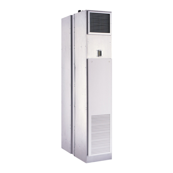
Carrier 42S Series Installation, Start-Up And Service Instructions Manual
Fan coil air conditioners
Hide thumbs
Also See for 42S Series:
- Instruction manual (44 pages) ,
- Product data (140 pages) ,
- Installation, start-up and service instructions manual (82 pages)
Table of Contents
Advertisement
Installation, Start-Up and Service
CONTENTS
SAFETY CONSIDERATIONS . . . . . . . . . . . . . . . . . . 1
INTRODUCTION . . . . . . . . . . . . . . . . . . . . . . . . . . . . 2
PHYSICAL DATA . . . . . . . . . . . . . . . . . . . . . . . . . . . 2
PRE-INSTALLATION . . . . . . . . . . . . . . . . . . . . . . . . 2
Unpack and Inspect Units . . . . . . . . . . . . . . . . . . . . 2
Protect Units From Damage . . . . . . . . . . . . . . . . . . 2
Prepare Jobsite for Unit Installation . . . . . . . . . . . 3
Identify and Prepare Units. . . . . . . . . . . . . . . . . . . 13
INSTALLATION. . . . . . . . . . . . . . . . . . . . . . . . . . . . 13
Step 1 - Place Units in Position . . . . . . . . . . . . . 13
Step 2 - Make Electrical Connections . . . . . . . . 22
Step 3 - Make Duct Connections . . . . . . . . . . . . 23
Step 4 - Frame and Finish Unit . . . . . . . . . . . . . . 23
Step 6 - Make Final Preparations . . . . . . . . . . . . 24
START-UP . . . . . . . . . . . . . . . . . . . . . . . . . . . . . . . . 25
Cooling/Heating System . . . . . . . . . . . . . . . . . . . . 25
Air System Balancing . . . . . . . . . . . . . . . . . . . . . . 26
Water System Balancing . . . . . . . . . . . . . . . . . . . . 26
Water Treatment. . . . . . . . . . . . . . . . . . . . . . . . . . . 26
Controls Operation . . . . . . . . . . . . . . . . . . . . . . . . 26
SERVICE . . . . . . . . . . . . . . . . . . . . . . . . . . . . . . . . . 26
Excessive Condensation on Unit . . . . . . . . . . . . . 26
To Clean Coil . . . . . . . . . . . . . . . . . . . . . . . . . . . . . 27
Check Drain . . . . . . . . . . . . . . . . . . . . . . . . . . . . . . 27
Fan Motor Bearings . . . . . . . . . . . . . . . . . . . . . . . . 27
Clean Fan Wheel . . . . . . . . . . . . . . . . . . . . . . . . . . 27
Clean Electric Heater . . . . . . . . . . . . . . . . . . . . . . . 27
Electrical Wiring and Controls . . . . . . . . . . . . . . . 27
Valves and Piping . . . . . . . . . . . . . . . . . . . . . . . . . 27
Filters . . . . . . . . . . . . . . . . . . . . . . . . . . . . . . . . . . . 27
Drain . . . . . . . . . . . . . . . . . . . . . . . . . . . . . . . . . . . . 27
Warranty . . . . . . . . . . . . . . . . . . . . . . . . . . . . . . . . . 28
Manufacturer reserves the right to discontinue, or change at any time, specifications or designs without notice and without incurring obligations.
Catalog No. 04-53420017-01
Instructions
Printed in U.S.A.
Form 42S-4SI
Fan Coil Air Conditioners
CONSTRUCTION . . . . . . . . . . . . . . . . . . . . . . . .29
ADJUSTMENT . . . . . . . . . . . . . . . . . . . . . . . . . .32
ADJUSTMENT . . . . . . . . . . . . . . . . . . . . . . . . . .33
SAFETY CONSIDERATIONS
Installation of this unit can be hazardous due to electrical
components and equipment location (such as an elevated
structure). Only trained, qualified installers and service me-
chanics should install and service this equipment.
See Fig. 1 for the Proposition 65 warning label.
CAUTION
When installing this unit, observe precautions in the liter-
ature, labels attached to the equipment, and any other
safety precautions that apply.
•
Follow all safety codes.
•
Wear safety glasses and work gloves. Never wear
bulky or loose fitting clothing when working on any
mechanical equipment. Gloves should be worn for
proper protection against heat and other possible inju-
ries. Safety glasses or goggles should always be worn
when drilling, cutting, or working with chemicals
such as refrigerants or lubricants.
•
Use care in handling and installing this unit.
•
Never pressurize any equipment beyond specified test
pressures. Always pressure-test with an inert fluid or
gas such as clear water or dry nitrogen to avoid possi-
ble damage or injury in the event of a leak or compo-
nent failure during testing. Always protect adjacent
flammable material when welding or soldering. Use a
suitable heat-shield material to contain sparks or drops
of solder. Have a fire extinguisher readily available.
WARNING
ELECTRICAL SHOCK HAZARD
Failure to follow this warning could cause personal injury or
death.
Before performing installation, service, or maintenance opera-
tions on unit, turn off main power switch to unit and install
lock(s) and lockout tag(s). Ensure electrical service to unit
agrees with voltage and amperage listed on the unit rating
plate. Unit may have more than one power switch.
Pg 1
42S Series
8-18
Replaces: 42S-3SI
Advertisement
Table of Contents

Related Manuals for Carrier 42S Series


Summary of Contents for Carrier 42S Series
-
Page 1: Table Of Contents
Unpack and Inspect Units ....2 START-UP CHECKLIST FOR 42S SERIES FAN COIL AIR CONDITIONERS ..CL-1 Protect Units From Damage . -
Page 2: Introduction
Carrier should be notified. In the event a claim for shipping damage is filed, the unit, shipping carton, and all packing must be retained for physical inspection by the transportation company. -
Page 3: Prepare Jobsite For Unit Installation
Table 1 — Physical Data — 42S Series Units UNIT SIZE 42S NOMINAL AIRFLOW (cfm) - Page 4 LEGEND CR — Cold Water Return CS — Cold Water Supply — Drain ITEM DESCRIPTION HR — Hot Water Return HS — Hot Water Supply Electrical Knockouts — Return 3-in. Expanded Section — Supply Strip Heater (Optional) *Drawing provided for reference only. Dimensions may vary with options ordered. Limit Switch**††...
- Page 5 LEGEND CR — Cold Water Return CS — Cold Water Supply — Drain HR — Hot Water Return HS — Hot Water Supply ITEM DESCRIPTION — Return — Supply Full Riser Chase Electrical Knockouts *Drawing provided for reference only. Dimensions may vary with options ordered. NOTES: 3-in.
- Page 6 3-5/8(92)* 3(76) TOP VIEW 4-PIPE 3(76) OPTION 3-5/8(92) 1-1/4 (32) 3 (76) 3 (76) 1 (25) 2558 (NOTE7) (1372) (1600) 5 (127) LEGEND CR — Cold Water Return CS — Cold Water Supply D — Drain HR — Hot Water Return HS —...
- Page 7 LEGEND CR — Cold Water Return CS — Cold Water Supply D — Drain HR — Hot Water Return HS — Hot Water Supply R — Return S — Supply *Drawing provided for reference only. Dimensions may vary with options ordered. ITEM DESCRIPTION NOTES:...
- Page 8 LEGEND CR — Cold Water Return CS — Cold Water Supply D — Drain HR — Hot Water Return HS — Hot Water Supply R — Return S — Supply *Drawing provided for reference only. Dimensions may vary with options ordered. ITEM DESCRIPTION NOTES:...
- Page 9 (76) ITEM DESCRIPTION (76) 3-5/8 3-5/8 Float Switch (Optional) (92) 1-1/4 (92) (32) Drain Pan Flexible Drain Tube/P-Trap 1 each 1-1/4 Drain Knockout (3 Sides) side (32) Blower (102) Riser Knockouts (3 Sides) 1-1/4 (32) -in. Flare Adaptor (SWT x 37.5) Coil, -in.
- Page 10 (76) (76) 3-5/8 3-5/8 (92) 1-1/4 (92) (32) CR CS 1-1/4 (32) (102) 1-1/4 (32) TOP VIEW DETAIL SIDE VIEW ITEM DESCRIPTION Float Switch (Optional) Drain Pan Flexible Drain Tube/P-Trap 1 each Drain Knockout (3 Sides) side Limit Switch (Factory Installed) Strip Heater (2235) Blower...
- Page 11 (76) (76) (76) (76) 3-5/8 3-5/8 (92) 1-1/4 1-1/4 (92) (32) (32) (280) (280) ELECTRICAL KNOCKOUTS (76) (76) (610) (610) 4-PIPE 2-PIPE 1 (25) 1 (25) 4 (102) 4 (102) (559) (559) SUPPLY PLENUM (OPTIONAL) (406) (406) SUPPLY (559) SUPPLY AIR TOP DUCT OPENING 4-3/4 (121)
- Page 12 PANEL DIMENSIONS (in.) PANEL UNIT UNIT SIZE 03, 04 15.5 42SG,SJ, 06, 08 19.5 10, 12 23.5 42SM 14,16,20 29.5 03, 04 15.5 42SG,SJ 06, 08 19.5 10, 12 23.5 03, 04 15.2 42SG,SJ 06, 08 19.2 55.3 10, 12 23.2 55.5 61.1...
-
Page 13: Identify And Prepare Units
PANEL AND FRAME DIMENSIONS (in.) PANEL NO. UNIT UNIT SIZE 03, 04 15.1 42SG,SJ, 06, 08 19.1 10, 12 23.1 03, 04 15.1 42SG,SJ 06, 08 19.1 10, 12 23.1 NOTE: Dimensions in inches. 60.4 60.4 54.7 51.7 PANEL NO. 4 FOR 42SU PANEL NO. -
Page 14: 42Sg, Sh, And Sj Units
handling. Never use the riser to lift the unit. To maintain the straight and square cabinet alignment, avoid lifting or sup- porting the cabinet only at the top and bottom. 42SJA 42SJA While the manufacturer does not become involved in the de- sign and selection of support methods and components, it should be noted that unacceptable system operating charac- teristics and/or performance may result from improper or in-... - Page 15 After units are positioned and riser centered in pipe chase, make unit plumb in two directions, using unit INSTALL WALL GYPSUM frame as a reference. WALL STUDS BOARD c. Anchor unit to building. Use bolts or lag screws (TO WALL AND through holes provided in unit frame.
-
Page 16: 42Su Universal Arrangement
water piping and valves are located over the drain pan REAR and need not be insulated. (RISER SIDE) 11. If required, fireproof where necessary. Any fireproofing requirements where risers or piping penetrate floors or walls are the responsibility of the installer. This work should be done only after all pressure testing is com- 42SU RIGHT... - Page 17 SIDE VIEW DRAIN INSULATION SUPPLY AND RETURN CUT LINE INSULATION CUT LINE SIDE SUPPLY AIR KNOCKOUT (1 PER SIDE) Fig. 19 — 42SU Unit Knockout Insulation Removal CAUTION OPTIONAL ELECTRICAL KNOCKOUTS Toxic residues and loose particles resulting from manu- facturing and field piping techniques such as joint com- pounds, soldering flux, and metal shavings may be pres- ent in the unit and the piping system.
- Page 18 knockouts, making sure the insulation penetrates into the BALL unit as shown in Fig. 20-23. VALVE WRENCH Before anchoring the equipment in place, the unit must be leveled and the cabinet must be plumb and squared. The unit may be anchored in place by bolting directly through the unit floor or attaching to the cabinet in some location that will not interfere with drywall or other items such as the supply grille, thermostat, or return...
-
Page 19: 42Sm Units
also allow risers to be drained down after testing in the can now be used as drywall stops to prevent coverage of winter to avoid freeze-up problems. In the event that discharge opening (see Fig. 25). leaking or defective components are discovered, the DUCT FLANGE sales representative must be notified BEFORE any repairs are attempted. - Page 20 Supply, Return, and Drain Risers FLEXIBLE CAUTION HOSE KIT RISER STUBOUT Toxic residues and loose particles resulting from manu- INSULATION BALL facturing and field piping techniques such as joint com- VALVE RISER pounds, soldering flux, and metal shavings may be pres- ent in the unit and the piping system.
- Page 21 Locate the unit’s coil fitting. field-supplied isolation ball valve is installed between The plastic flare caps on the end of the coil fitting should each supply and return piping connection to the unit. be removed and discarded. Flare fittings are factory provided to allow connection Use a wrench to tighten the swivel connections.
-
Page 22: Step 2 - Make Electrical Connections
codes and ordinances. Compliance with all codes is the re- TOP VIEW sponsibility of the installing contractor. The fan motor(s) should never be controlled by any wiring or device other than the factory-supplied switch or thermostat/ switch combination unless prior factory authorization is ob- tained. -
Page 23: Standard Wiring Packages
STANDARD WIRING PACKAGES Normally an automatic changeover thermostat is used, but a manual changeover thermostat is also suitable. Two 2-way Thermostatic Electric Valve Control, 2-Pipe valves, two 3-way valves, or one 2-way plus one 3-way valve A thermostatically controlled 2-position valve provides supe- must be selected. -
Page 24: Step 5 - Cut Out Openings For Grilles And Thermostats
heating performance and could experience excessive or pre- Install filter in frame at front of coil. If field-supplied fil- mature component failures. ters are used, be sure size is as specified in Table 1. Prevent sheetrock dust or other debris from settling on coil fins, motor-blower assembly or other unit interior surfaces. -
Page 25: Start-Up
Fig. 35 — ECM Rheostat Speed Board (42SM Only) The building must be completely finished including doors, Carrier’s convention is to preset and wire Flo1 for high speed, windows, and insulation. All internal walls and doors should Flo2 for medium, and Flo3 for low. Flo4 is not used with any be in place and in the normal position. -
Page 26: Air System Balancing
During system filling, air venting from the unit is accom- plished by the use of standard manual air vent or optional au- Carrier’s water coil tubes and headers are constructed of pure tomatic air venting installed on the coil. Manual air vents are copper. -
Page 27: To Clean Coil
limit thermal cutout device and may not be evident until actu- To Clean Coil al heater element failure. Be sure electrical service switch is open, locked, and tagged while working on unit. Electrical Wiring and Controls Remove return-air grille access panel and brush between The electrical operation of each unit is determined by the coil fins with stiff wire brush. -
Page 28: Warranty
and line are clear. If it is clogged, take steps to clear the debris Warranty so that condensate will flow easily. All equipment and components sold through the Parts De- Make periodic checks of the drain during the cooling season partment are warranted under the same conditions as the stan- to maintain a free flowing condensate. -
Page 29: Appendix A - Block-Out Construction
APPENDIX A — BLOCK-OUT CONSTRUCTION This section provides rough guidelines for the block-out slot Table B — SHORT 79-IN. CABINET, TWO-PIPE size for 42S units with risers included. Therefore, the floor UNITS block-out slot dimensions listed in this document should be BLOCK-OUT CONSTRUCTION SIZE considered estimates. - Page 30 APPENDIX A — BLOCK-OUT CONSTRUCTION (cont.) Table C — STANDARD 88-IN. CABINET (Four-Pipe Table D — SHORT 79-IN. CABINET (Four-Pipe 42S Units) 42S Units) BLOCK-OUT CONSTRUCTION SIZE BLOCK-OUT CONSTRUCTION SIZE TYPE OF INSTALLATION TYPE OF INSTALLATION TYPE 1 TYPE 2 TYPE 3* TYPE 1 TYPE 2...
- Page 31 APPENDIX A — BLOCK-OUT CONSTRUCTION (cont.) BLOCK-OUT WIDTH UNIT BLOCK-OUT LENGTH RISER COLUMN FLOOR PENETRATION (BLOCK-OUT) FLOOR UNIT RISER LENGTH* CLEAR HEIGHT FLOOR TO FLOOR FLOOR SLAB THICKNESS NOTE: Riser Length = Floor-to-floor dimensions ± 2-in. (maximum riser length of 115-in. When riser length must exceed 115-in. use 104-in.
-
Page 32: Appendix B - Potentiometer Adjustment
APPENDIX B — POTENTIOMETER ADJUSTMENT Fig. C — 3-Speed ECM Adjusting the low, medium, and high potentiometers requires Attach the red (positive) lead of the meter to the red wire the use of a multi-meter capable of measuring 0~5 vdc (See that bridges the 0-10 vdc outputs: high, medium, and Fig. -
Page 33: Appendix C - Evo/Ecm 4-Speed Adjustment
Attach black (negative) lead of meter to the “Com” ter- speed operation. minal to the left of the potentiometers and below the sta- For setting of Flo0 and Flo4, contact Carrier, otherwise tus light. these potentiometers should be set to full counter-clock- Attach the red (positive) lead of the meter to the high wise rotation. - Page 34 © Carrier Corporation 2018 Manufacturer reserves the right to discontinue, or change at any time, specifications or designs without notice and without incurring obligations. Catalog No. 04-53420017-01 Printed in U.S.A. Form 42S-4SI Pg 34 8-18 Replaces: 42S-3SI...
-
Page 35: Start-Up Checklist For 42S Series Fan Coil Air Conditioners
START-UP CHECKLIST FOR 42S SERIES FAN COIL AIR CONDITIONERS NOTE: To avoid injury to personnel and damage to equipment or prop- erty when completing the procedures listed in this start-up checklist, use good judgment, follow safe practices, and adhere to the safety considerations/information as outlined in preceding sections of this Installation, Start-Up, and Service Instructions document. - Page 36 © Carrier Corporation 2018 Manufacturer reserves the right to discontinue, or change at any time, specifications or designs without notice and without incurring obligations. Catalog No. 04-53420017-01 Printed in U.S.A. Form 42S-4SI Pg CL-2 8-18 Replaces: 42S-3SI...
Need help?
Do you have a question about the 42S Series and is the answer not in the manual?
Questions and answers