Carrier 42C Series Product Data
Fan coil air conditioners 50/60 hz 150 to 2000 cfm
Hide thumbs
Also See for 42C Series:
- Product data (140 pages) ,
- Installation instructions manual (100 pages) ,
- Installation, start-up and service instructions manual (82 pages)
Table of Contents
Advertisement
42SH STACK
Copyright 2011 Carrier Corporation
Product
Data
42CA HORIZONTAL
42DA DUCTED
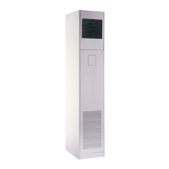
42VB VERTICAL
42C,D,S,V Series
Fan Coil
Air Conditioners
50/60 Hz
150 to 2000 cfm
Carrier's 42C,D,S,V Series fan coil
units offer:
• Design flexibility, occupying minimum
space
• Easy, low-cost installation
• Permanent split capacitor motors
deliver peak operating efficiency
• High performance, low cost
• Greater zone comfort control
Features/Benefits
Carrier's extensive range of
superior fan-coil units
combine design flexibility
with easy, low-cost
installation.
Versatility
With Carrier's 42 Series fan coils, you
can select from 6 horizontal, 6 vertical,
5 ducted or 5 stacked models; furred-in
or cabinet style, slant top or low silhou-
ette, in 150 through 2000 cfm capaci-
ties. Coils are available with 1, 2, 3, 4,
or 5 rows (depending on model), to sat-
isfy a variety of application require-
ments. The units are ideal for installa-
tion in motels, apartments, and other
multi-room buildings. Many optional
control packages are available, including
2-pipe heating and cooling, 2-pipe
heating and cooling with auxiliary elec-
tric heat, 2-pipe cooling with total elec-
tric heat, and 4-pipe heating and cool-
ing. Also offered are manual and auto-
matic changeover controls and several
thermostats.
Casings and frame are fabricated from
tough, heavy gage galvanized steel. Op-
tional decorative colors allow the unit to
blend with any interior design.
Form 42-7PD
Advertisement
Table of Contents

Related Manuals for Carrier 42C Series


Summary of Contents for Carrier 42C Series
- Page 1 Versatility With Carrier’s 42 Series fan coils, you can select from 6 horizontal, 6 vertical, 5 ducted or 5 stacked models; furred-in or cabinet style, slant top or low silhou- ette, in 150 through 2000 cfm capaci- ties.
-
Page 2: Table Of Contents
Series vertical units energy savings, sound absorption and Carrier room fan-coil units provide Carrier room fan coil units operate at indoor air quality (IAQ) preservation. unsurpassed year-round comfort, with exceptionally low sound levels. A Water never touches the pan, so corro-... - Page 3 The 42SG furred-in-stack is a single 42S stacked units unit installation, all risers are shipped unit, designed for concealed Each Carrier stack unit comes factory separately from the units for pre-instal- applications in corners or along room equipped with insulated supply, return, lation and testing purposes.
-
Page 4: Features/Benefits
Features/Benefits (cont) 42CA Furred-in ceiling model with low silhouette. (200-1200 cfm) 42CG Cabinet model for under-ceiling mount with bottom or rear stamped louver return air grille. (200-1200 cfm) 42CE Furred-in ceiling model with factory-installed plenum. 42CH (200-1200 cfm) High-static, furred-in model. (400-1000 cfm) 42CK Cabinet model with telescoping flip-down panel... - Page 5 42VC Furred-in lowboy model for concealed under- 42VA the-window applications. (200-600 cfm) Furred-in model for under-the-window applications with top or front discharge. (200-1200 cfm) 42VE Cabinet lowboy model with stamped louver dis- charge grille and 2 control access doors. (200-600 cfm) 42VB Cabinet model with top or front discharge.
- Page 6 Features/Benefits (cont) 42-68d 42DD 42DA Vertical model with galvanized casing. Furred-in model for installation in the Commonly for closet installation. ceiling or over the closet. (600-2000 cfm) (600-2000 cfm) 42DE Ceiling model with galvanized casing. (600-2000 cfm) 42DC Furred-in ceiling model with factory-installed insulated plenum.
- Page 7 42SJ — Back-to-back 42SH — Cabinet stack 42SG — Furred-in-stack furred-in stack (300-1200 cfm) (300-1200 cfm) (300-1200 cfm) 42-100d 42SM — Mega furred-in-stack 42SU — Universal furred-in-stack (1400-2000 cfm) (300-1200 cfm) a42-4148 a42-4260...
-
Page 8: Options
6 in. Opening with Manual Sliding Damper Outside-Air Knockouts Outdoor-Air Connection ETO ETO ETO ETO ETO ETO ETO ETO DECORATIVE COLORS See Carrier Paint Selector Guide DISCHARGE GRILLES Stamped Discharge Std Std Std Std Double Deflection, Factory-Installed† Double Deflection, Shipped Loose†... - Page 9 AVAILABLE OPTIONS (cont) UNIT SERIES — 42 OPTIONS OR STANDARD FEATURES* Ceiling — Horizontal Floor — Vertical Ducted — Horizontal Stack — Vertical DUCT COLLAR Discharge Std Std Std Std Std Std Std Std Std Discharge Knockouts ELECTRIC HEATERS Nichrome Wire Strip Heater Sheath Type Heater FAN SWITCH Unit-Mounted and Factory Wired...
- Page 10 6-Row Coil — • — — are available for all 42C Series except 42CA, CH; 42DC, Opposite End Coil Connections DD, DE; all 42V Series except 42VG; and all 42S Series 42VA,VB, except 42SU, SM units.
- Page 11 Thermostat control packages — We offer a variety of Condensate drains are available in sizes down to 1-in. for control devices to meet the most basic to the most greater cost economy. Riser size-reducers are factory-in- demanding operating logic. All of our control schemes uti- stalled on 42SG, SJ, and SH.
-
Page 12: Options
Options (cont) Tell-tale drain pan — A secondary drain connection is 42SM units. Wall-mounted line voltage and 24-v thermo- located above the primary drain to act as a “tell-tale” in the stats are available on the 42 Series fan coil units. For ther- event that the primary drain becomes obstructed. -
Page 13: Controls
Controls Use the Control Selection Guide table to make sure that all NOTE: When thermostatic fan control is selected or when necessary components are provided for and that the com- unit outside-air dampers are used, unit-mounted thermo- ponents are compatible with the required control system. stats are not recommended as their use will result in poor room temperature sensing. - Page 14 Controls (cont) Remote-mounted controls Optional remote-mounted line-voltage thermostat 3-SPEED SWITCH LINE VOLTAGE T155 THERMOSTAT Line voltage T155 thermostat — Features 50 to 90 F temperature range, manual 3-speed fan control, mount is a standard 2 x 4 in. box, 4-pipe, 2-pipe and autochangeover applications.
- Page 15 The fan coil open controller also features plug-and-play connectively to Carrier’s i-Vu ® open control system. For added flexibility, the fan coil controller is capable of stand alone operation, or can be integrated with any Building Automation System (BAS) utilizing BACnet* protocol.
-
Page 16: Controls
Controls (cont) Automatic changeover (Summer-Winter switch) — The automatic-changeover thermostat sensor is a 10 kilo- FAN COIL CONTROL RELAY BOARD ohm thermister (33ZCSENCHG) in a moistureproof and dust-proof enclosure. Cable and temperature sensing ele- ment are hermetically sealed in a polypropylene enclosure with epoxy resin. -
Page 17: Selection Procedure
Selection procedure Refer to the Carrier Electronic Selection Program for infor- mation to determine unit sizing for your needs. Application data Basic definitions Unit hand — When facing the supply air outlet from the Opposite end connection (4-pipe option) — Hot... - Page 18 Application data (cont) System piping The following diagrams show some common methods SYSTEM 2 — REVERSE RETURN used to pipe the 42S Series units. Only the 2-pipe systems are shown; however, the methods would be the same for 4-pipe systems. System 1, the “direct return”...
- Page 19 Risers (42S units) by 3 gpm per floor, so that after 3 floors, the total flow is 21 gpm and riser size can be reduced to one inch. See Riser diameter is an important consideration in the design chart on page 118. of stack series systems.
- Page 20 Application data (cont) TYPICAL ARRANGEMENT APPLICATIONS a42-3987...
- Page 21 42SU ARRANGEMENT OPTIONS One of the unique traits of the Universal Stack (42SU) is the variety of possible unit arrangements. The best unit design configuration can be selected by choosing from numerous unit arrangement options that utilize knock-out designs while conserving floor space and reducing installation costs. Below are just a few pictorials of the many arrangement possibilities of the 42SU fan coil system.
- Page 22 Application data (cont) 42SM UNIT CONFIGURATION OPTIONS Mega Stack units (42SM) are designed to be installed either in a small mechanical closet or furred in with drywall adhered directly to the cabinet. One of the unique traits of the 42SM unit is its optional discharge plenum.
- Page 23 PIPING COMPONENTS FACTOR RATING* STEAM SYMBOL/SKETCH DESCRIPTION MANUAL AIR VENT: Threaded brass needle valve with screwdriver slot for adjustment. Application — Body brazed into high point of heating and cooling coils for bleeding air from coil. Standard item on all hydronic coils (not used on steam or DX coils).
- Page 24 Application data (cont) PIPING COMPONENTS (cont) FACTOR RATING STEAM SYMBOL/SKETCH DESCRIPTION BALANCE VALVE: Variable water flow man- ual balancing valve with screwdriver slot adjustment screw. Application — Often used in conjunction with test port fittings for water flow balancing. Bal- ance by temperature differential or coil pres- sure drop (check specifications for service fittings required if balancing by pressure drop).
- Page 25 PIPING COMPONENTS (cont) FACTOR RATING STEAM SYMBOL/SKETCH DESCRIPTION 2-WAY MOTORIZED VALVE (25 PSI close off differential pressure): Electric 2-position flow control valve (open/closed). Normally closed body with manual override lever. Installed in supply line to unit. Application — All standard control and valve packages are based upon normally closed valves (valve electrically powered open and closed by spring return when electric power...
- Page 26 Application data (cont) PIPING COMPONENTS (cont) FACTOR RATING STEAM SYMBOL/SKETCH DESCRIPTION MODULATING VALVE (Optional) (Non-Spring Return, Floating Point Actua- tor): Modulating valves are designed to con- trol the flow in the circuit by making incremental adjustments to the flow path within the valve.
-
Page 27: Valve Packages
Valve packages Valve packages are shipped with the units or in unit car- tons. Valve packages include belled ends for field soldering There are limitations on physical size of pneumatic valves, to coil connections. quantity and type of matching components, and required control interface. - Page 28 Application data (cont) VALVE PACKAGE ARRANGEMENTS LEGEND Ball Valve Ball Valve with Memory Stop Circuit Setter Motorized 2-Way Valve Motorized 3-Way Valve *When aquastat is used for automatic changeover, bypass is required as indicated by dashed line. NOTES: a42-3988 1. Packages factory furnished and field installed (except 42S units). 2.
- Page 29 VALVE PACKAGE SPACING RECOMMENDATIONS 25" VALVE CABINET PACKAGE AREA 9-1/4" 9-1/2" 42VAA (SEE NOTE 3) PLENUM COIL HEIGHT OF COIL VALVE PACKAGE AREA 18" DRAIN PAN 24" 42CEA, CFA, DCA (SEE NOTES 1, 2) 14-3/8" VALVE (SEE PACKAGE NOTE 4) CABINET AREA NOTES:...
- Page 30 Application data (cont) Cv FACTOR VS WATER PRESSURE DROP FACTOR: The flow rate in gallons per minute (gpm) through a piping component when the pressure drop (P) in pounds per square inch (psi) across the component is 1.0 (psi). Pressure drop (ft-H O) = 2.31 x psi (pressure drop) GRAPH EXAMPLE: P for 2.0 gpm through a component with a C...
- Page 31 ENTHALPY AT SATURATION ENTHALPY AT ENTHALPY AT TEMPERATURE SATURATION TEMPERATURE SATURATION (Btu per lb (Btu per lb of dry air) of dry air) 15.230 26.46 15.697 27.15 16.172 27.85 16.657 28.57 17.149 29.31 17.650 30.06 18.161 30.83 18.680 31.62 19.211 32.42 19.751 33.25...
- Page 32 42S stack units, the strip heater is located in the fan dis- charge on the leaving side of the coil. Electric heaters are available for installation on Carrier fan Sheath heaters are used with Model 42V vertical units. coil units in the following applications.
- Page 33 17,075 NOTES: 240,277 20,490 1. Contact your Carrier representative for heater availability on 42SU NOTE: All heaters are single-stage and single-phase. Contact your unit quick ship program. Carrier representative for heater availability for 220-1-50 units. 2. 12 kW heater only available with 277V heater voltage.
-
Page 34: Application Data
Application data (cont) ECM motor control methods fan speed with more precision than the predetermined fan speed percentage in control method no. 1. Customer can There are three main control methods to control the speed connect a voltmeter to the rheostat knobs and adjust the of electronically commutated motor (ECM) for desirable air- voltage output of each fan speed to slow down or speed up flow for a given application. -
Page 35: Model Number Nomenclature
Model number nomenclature *Model 42CG only. a42-4098.eps... -
Page 36: Ahri Capacity Ratings
AHRI capacity ratings The 42C,V Series fan coil units are certified in compliance with the Air Conditioning, Heating and Refrigeration Insti- tute (AHRI) Industry Standard 440 for room fan coil units. Approved standard ratings are tabulated below: AHRI APPROVED STANDARD RATINGS* COOLING CAPACITY UNIT COIL... - Page 37 SOUND POWER DATA 42CA,CE,CK SOUND RATINGS — OCTAVE BAND POWER LEVEL RATINGS* (dB) SOUND POWER LEVEL, L (dB one reference pico watt) — Hz A-wgt SIZE RATING SPEED (dBA) 1000 2000 4000 8000 High CASING Medium RADIATED High DISCHARGE Medium High CASING Medium...
- Page 38 AHRI capacity ratings (cont) SOUND POWER DATA 42CG SOUND RATINGS — OCTAVE BAND POWER LEVEL RATINGS* (dB) SOUND POWER LEVEL, L (dB one reference pico watt) — Hz A-wgt SIZE RATING SPEED (dBA) 1000 2000 4000 8000 High CASING Medium RADIATED High CASING...
- Page 39 SOUND POWER DATA (cont) 42VA,VB,VF SOUND RATINGS — OCTAVE BAND SOUND POWER LEVEL RATINGS* (dB) SOUND POWER LEVEL, L (dB one reference pico watt) — Hz A-wgt SIZE RATING SPEED (dBA) 1000 2000 4000 8000 High CASING Medium RADIATED High CASING Medium RADIATED...
-
Page 40: Physical Data
— — 1.02 1.42 1.71 2.32 — COILS 10 fins/inch Coil Face Area (sq ft)† MOTOR (qty) 42C Series BLOWER (qty) 42CA, CE, CG, CK 42CF, CH — — — FILTERS Nominal Size (in.) (1-in. thick) 42CA** 10 x 24... -
Page 41: Base Unit Dimensions
Base unit dimensions 42CA FURRED-IN HORIZONTAL UNIT NOTES: LEGEND 1. Right hand unit shown; left hand unit opposite. Coil connection loca- 1 — Junction Box (remote mount) tions are ± -inches. 2 — Flexible Metal Conduit 2. Unit sizes 02 and 03 have one motor, one blower; sizes 04 through 3 —... - Page 42 Base unit dimensions (cont) 42CA FURRED-IN HORIZONTAL UNIT WITH ELECTRIC HEAT NOTES: LEGEND 1. Right hand unit shown; left hand unit opposite. Coil connection loca- 1 — Junction Box (remote mount) tions are ± -inches. 2 — Flexible Metal Conduit 2.
- Page 43 42CE FURRED-IN HORIZONTAL UNIT WITH PLENUM LEGEND NOTES: 1. Right hand unit with standard 3-row coil shown; left hand unit opposite. Coil 1 — Junction Box, 4 in. x 4 in. connection locations are ± -inches. 2 — Flexible Metal Conduit 2.
- Page 44 Base unit dimensions (cont) 42CE FURRED-IN HORIZONTAL UNIT WITH PLENUM AND ELECTRIC HEAT NOTES: LEGEND 1. Right hand unit with standard 3-row coil shown; left hand unit opposite. Coil 1 — Junction Box, 4 in. x 4 in. connection locations are ± -inches.
- Page 45 42CF FURRED-IN HIGH-STATIC HORIZONTAL UNIT WITH PLENUM NOTES: LEGEND 1. Right hand unit shown; left hand unit opposite. Coil connection 1 — Junction Box, Installed with Plenum locations are ± -inches. 2 — Flexible Metal Conduit 2. Unit sizes 04 thru 08 have one motor, 2 blowers; size 10 has 3 —...
- Page 46 Base unit dimensions (cont) 42CF FURRED-IN HIGH-STATIC HORIZONTAL UNIT WITH PLENUM AND ELECTRIC HEAT NOTES: LEGEND 1. Right hand unit shown; left hand unit opposite. Coil connection 1 — Junction Box, Installed with Plenum locations are ± -inches. 2 — Plenum 2.
- Page 47 42CG HORIZONTAL CABINET UNIT NOTES: LEGEND 1. Right hand unit shown; left hand unit opposite. Coil connection 1 — Junction Box, 4 in. x 4 in. locations are ± -inches. 2 — Optional Return Air Location 2. Unit sizes 02 and 03 have one motor, one blower; sizes 04 3 —...
- Page 48 Base unit dimensions (cont) 42CG HORIZONTAL CABINET WITH ELECTRIC HEAT NOTES: LEGEND 1. Right hand unit shown; left hand unit opposite. Coil connection 1 — Junction Box, 4 in. x 4 in. locations are ± -inches. 2 — Optional Stamped Rear Return Grille 2.
- Page 49 42CH FURRED-IN HIGH-STATIC HORIZONTAL UNIT FLEXIBLE METAL CONDUIT OPTIONAL (25) 5/8"(16) O.D. TELL-TALE DRAIN 7/8"(22) O.D. CONNECTION, CONDENSATE AVAILABLE DRAIN ON STANDARD JUNCTION BOX AND EXTENDED (REMOTE MOUNT) DRAIN PANS 6(152) OPTIONAL EXTENDED 1-1/2 DRAIN PAN (SEE NOTE 2) (38) 1-1/8 MTG.
- Page 50 Base unit dimensions (cont) 42CH FURRED-IN HIGH-STATIC HORIZONTAL UNIT WITH ELECTRIC HEAT FLEXIBLE METAL CONTACTOR BOX CONDUIT (REMOTE MOUNT) OPTIONAL 5/8"(16) O.D. STRIP HEATER TELL-TALE DRAIN CONNECTION, AVAILABLE (25) ON STANDARD AND EXTENDED DRAIN PANS 7/8"(22) O.D. CONDENSATE DRAIN (152) 1-1/2(38) OPTIONAL EXTENDED 1-1/8...
- Page 51 42CK HORIZONTAL CABINET UNIT WITH TELESCOPIC ACCESS PANEL, FRONT SUPPLY, AND BOTTOM RETURN A42-4149 LEGEND NOTES: 1. Right hand unit shown; left hand unit opposite. 1 — Junction Box 2. Internal factory valve package and drains may not align with cabinet 2 —...
- Page 52 Base unit dimensions (cont) 42CK HORIZONTAL CABINET UNIT WITH TELESCOPIC ACCESS PANEL, FRONT SUPPLY, BOTTOM RETURN, AND HEATER a42-4150 LEGEND NOTES: 1. Right hand unit shown; left hand unit opposite. 1 — Contactor Box 2. Internal factory valve package and drains may not align with 2 —...
- Page 53 42CK HORIZONTAL CABINET UNIT WITH TELESCOPIC ACCESS PANEL, FRONT SUPPLY, AND REAR RETURN a42-4151 LEGEND NOTES: 1. Right hand unit shown; left hand unit opposite. 1 — Junction Box 2. Internal factory valve package and drains may not align with 2 —...
- Page 54 Base unit dimensions (cont) 42CK HORIZONTAL CABINET UNIT WITH TELESCOPIC ACCESS PANEL, FRONT SUPPLY, REAR RETURN, AND HEATER a42-4152 LEGEND NOTES: 1. Right hand unit shown; left hand unit opposite. 1 — Contactor Box 2. Internal factory valve package and drains may not align with 2 —...
- Page 55 42CK HORIZONTAL CABINET UNIT WITH TELESCOPIC ACCESS PANEL, BOTTOM SUPPLY, BOTTOM RETURN* LEGEND * ETO — Engineered to Order. NOTES: 1 — Junction Box, 4 in. x 4 in. 1. Right hand unit shown; left hand unit opposite. Coil connection 2 —...
- Page 56 Base unit dimensions (cont) 42CK HORIZONTAL CABINET WITH TELESCOPIC ACCESS PANEL BOTTOM SUPPLY, BOTTOM RETURN, AND ELECTRIC HEAT* LEGEND * ETO — Engineered to Order. NOTES: 1 — Junction Box, 4 in. x 4 in. 1. Right hand unit shown; left hand unit opposite. Coil connection 2 —...
- Page 57 42VA FURRED-IN VERTICAL UNIT LEGEND NOTES: 1. Right hand unit shown; left hand unit opposite. Coil connection 1 — Optional Unit Mounted Control Box locations are ± -inches. 2 — Wall Mounting Holes (4), -in. Diameter 2. Unit sizes 02 and 03 have one motor, one blower; sizes 04 through 3 —...
- Page 58 Base unit dimensions (cont) 42VB VERTICAL CABINET UNIT LEGEND NOTES: 1. Right hand unit shown; left hand unit opposite. Coil connection 1 — Standard Stamped Supply Grille locations are ± -inches. 2 — Access Door, Fan Switch 2. Unit sizes 02 and 03 have one motor, one blower; sizes 04 through 3 —...
- Page 59 42VF VERTICAL CABINET UNIT WITH SLANT TOP LEGEND NOTES: 1. Right hand unit shown; left hand unit opposite. Coil connection 1 — Standard Stamped Supply Grille locations are ± -inches. 2 — Access Door, Fan Switch 2. Unit sizes 02 and 03 have one motor, one blower; sizes 04 3 —...
- Page 60 Base unit dimensions (cont) 42VC FURRED-IN LOWBOY UNIT 14-3/8 (368) NOTES: LEGEND 1. Right hand unit shown; left hand unit opposite. Coil connection 1 — Optional Unit Mounted Control Box locations are ± -inches. 2 — Drain Pan, Auxiliary, Shipped Loose 2.
- Page 61 42VC FURRED-IN LOWBOY UNIT WITH ELECTRIC HEAT LEGEND NOTES: 1. Right hand unit shown; left hand unit opposite. Coil connection 1 — Unit-Mounted Control Box (Optional) locations are ± -inches. 2 — Drain Pan, Auxiliary, Shipped Loose 2. Unit sizes 02 through 04 have one motor, 2 blowers; size 06 has 3 —...
- Page 62 Base unit dimensions (cont) 42VE CABINET LOWBOY UNIT 14-3/8 (368) LEGEND NOTES: 1. Right hand unit shown; left hand unit opposite. Coil connection 1 — Fan Switch, 3-Speed, behind Access Door locations are ± -inches. 2 — Front Panel Fastener 2.
- Page 63 42VE CABINET LOWBOY UNIT WITH ELECTRIC HEAT NOTES: LEGEND 1. Right hand unit shown; left hand unit opposite. Coil connection 1 — Fan Switch, 3-Speed, behind Access Door locations are ± -inches. 2 — Electrical Sheath Heater Element 2. Unit sizes 02 through 04 have one motor, 2 blowers; size 06 has 3 —...
-
Page 64: Base Unit Dimensions
Base unit dimensions (cont) 42VG FURRED-IN WALL UNIT (OPTIONAL) LEGEND NOTES: 1. Right hand unit shown; left hand unit opposite. Coil connection 1 — Supply Conn, -in. OD locations are ± -inches. 2 — Air Vent, -in. MPT 2. Front panel has an Arctic White baked finish. 3 —... -
Page 65: Accessory Dimensions
Accessory dimensions OUTSIDE AIR OPENING/DAMPER DIMENSION A (in.) NOMINAL UNIT SIZE AIRFLOW VA,VB,VF VC,VE (CFM) Units Units — 1000 — 1200 — NOTES: 1. The above figure shows the outside air arrangement in 42V Series units. Manual or motorized dampers are available for 42VA,VB, and VF units. - Page 66 Accessory dimensions (cont)
- Page 67 a42-3994...
- Page 68 Accessory dimensions (cont) 42VC,VE OPTIONAL COIL CONNECTION LOCATION SIZES 02–06 NOTES: 1. Dimensions for split coils with opposite end connections will vary. 2. Coil connection dimensions are for coil stub outs only (valve packages not included). 3. All dimensions are in inches. 4.
- Page 69 DECORATIVE WALL PANELS (42VA units only) FRONT RETURN TOP SUPPLY FRONT RETURN AND SUPPLY WITH ACCESS DOORS a42-4193 UNIT SIZE A (in.) 30˝ 1000 1200 FRONT RETURN AND TOP SUPPLY WITH ACCESS DOORS (ETO) NOTE: ETO — Engineered To Order.
-
Page 70: Accessory Dimensions
Accessory dimensions (cont) DISCHARGE AIR GRILLES INTEGRAL DOUBLE-DEFLECTION GRILLE DISCHARGE GRILLES FOR HORIZONTAL UNITS Recommended Grille Sizes (in.) Nominal (Installed on 42CG Unit as Shown) Unit Airflow Unit Size (Cfm) 42C* 42VA 42VB,VF 42VC* 42VE 16 x 6 16 x 5 16 x 6 16 x 5 16 x 6... -
Page 71: Performance Data
Performance data AIR DELIVERY (CFM) 42C SERIES — 60 Hz MOTOR EXTERNAL STATIC PRESSURE (in. wg) 0.00 0.05 0.10 0.15 0.20 0.25 0.30 UNIT SIZE COIL Fan Speed High High High High High High High 3-Row — — — 4-Row —... - Page 72 Performance data (cont) AIR DELIVERY (CFM) (cont) 42V SERIES — 60 Hz MOTOR EXTERNAL STATIC PRESSURE (in. wg) 0.00 0.05 0.15 0.20 0.30 UNIT SIZE COIL Fan Speed High High High High High 3-Row — 4-Row — 3-Row 4-Row 3-Row 4-Row 3-Row 42VA,VB,VF...
- Page 73 HOT WATER HEATING CAPACITIES (MBtuh) — MODELS 42CA,CE,CF,CG,CH,CK,VA,VB,VF WATER FLOW (GPM) UNIT ROWS SIZE 10.0 12.0 — — — — — — 11.2 12.0 12.5 12.8 13.0 — — — — — — 12.0 14.0 15.3 16.2 16.8 17.1 — —...
-
Page 74: Performance Data
Performance data (cont) COOLING AND HEATING CAPACITIES (Btuh) — MODEL 42VG COOLING HEATING PRESSURE UNIT AIRFLOW WATER FLOW DROP Entering Water Temperature (F) SIZE (Cfm) (Gpm) (ft wg) 4,240 3,450 2,750 8,200 10,000 4,950 4,080 3,270 8,750 10,850 5,320 4,500 3,500 9,220 11,300... -
Page 75: Electrical Data
Electrical data ELECTRIC HEATER DATA HEATER kW HEATER 10.0 VOLTAGE 12.5 16.7 25.0 — — — — — 14.4 19.2 24.0 28.8 38.5 — 12.5 16.7 20.8 25.0 33.3 — 10.8 14.4 18.05 21.7 28.9 36.1 LEGEND FLA — Full Load Amps NOTE: All heaters are single-stage and single-phase. - Page 76 Electrical data (cont) 42C HIGH-STATIC PSC MOTOR DATA SIZE NOMINAL HP AMPS WATTS 42C*02 42C*03 42C*04 42C*06 42C*08 42C*10 42C*12 NOTES: 2. Motor amps and watts based on 115V motors. 1. High-static PSC motors are available on 42CA,CE,CK for 60 Hz voltages with a special quote.
- Page 77 42VA,VB, AND VF MOTOR DATA UNIT SIZE V-Ph-Hz SPEED SPEED (RPM) Nominal Hp Watts Amps Nominal Hp Watts Amps Nominal Hp Watts Amps Nominal Hp Watts Amps 1200 0.53 0.83 1.40 2.50 115-1-60 0.31 0.48 0.70 1.30 0.27 0.33 0.47 0.57 1200 0.48...
-
Page 78: Electrical Data
Electrical data (cont) 42VC,VE MOTOR DATA UNIT SIZE V-Ph-Hz SPEED SPEED Nominal Nominal (RPM) Watts Amps Watts Amps 1200 0.60 1.60 115-1-60 0.30 0.60 0.20 0.30 1200 0.50 0.66 208-1-60 0.20 0.30 1200 0.50 0.66 230-1-60 0.22 0.28 1200 0.30 0.50 277-1-60 0.12... -
Page 79: Model Number Nomenclature
Model number nomenclature LEGEND a42-3995 PSC — Permanent Split Capacitor AHRI capacity ratings The 42D Series fan coil units are certified in compliance with the Air Conditioning, Heating and Refrigeration Insti- tute (AHRI) Industry Standard 440 for room fan coil units. Approved standard ratings are tabulated below: AHRI APPROVED STANDARD RATINGS* COOLING CAPACITY... -
Page 80: Ahri Capacity Ratings
AHRI capacity rating (cont) SOUND POWER DATA 42DA, DC, DD, DE SOUND RATINGS — OCTAVE BAND SOUND POWER LEVEL RATINGS* (dB) SOUND POWER LEVEL, L (dB one reference pico watt) — Hz A-wgt SIZE RATING SPEED (dBA) 1000 2000 4000 8000 High CASING... -
Page 81: Physical Data
SOUND POWER DATA 42DF SOUND RATINGS — OCTAVE BAND SOUND POWER LEVEL RATINGS* (dB) SOUND POWER LEVEL, L (dB one reference pico watt) — Hz A-wgt SIZE RATING SPEED (dBA) 1000 2000 4000 8000 High CASING Medium RADIATED High CASING Medium RADIATED High... -
Page 82: Base Unit Dimensions
Base unit dimensions 42DA FURRED-IN CEILING UNIT WITH ELECTRIC HEAT LEGEND DIMENSIONS (in. ± QTY/UNIT UNIT UNIT 1 — Motor Junction Box WEIGHT* AIRFLOW 2 — Motor-Blower Assembly SIZE A’ D’ Blower Motor (lb) (Cfm) 3 — Electric Strip Heater Element (optional) 4 —... - Page 83 42DC FURRED-IN CEILING UNIT WITH PLENUM AND ELECTRIC HEAT DIMENSIONS (in. ± QTY/UNIT UNIT LEGEND UNIT WEIGHT* AIRFLOW SIZE 1 — Motor Junction Box Opposite Piping A’ D’ Blower Motor (lb) (Cfm) 2 — Insulated Return Air Plenum 3 — Mounting Clips (Shipped Loose) 4 —...
- Page 84 8. Units with internal factory valve packages have external connections located in triangu- lar section above coil. 9. Consult Carrier for ducted front return air and external filter rack with 1-in. duct collar and throwaway filters. 10. Units with electric heat require additional access on the side of unit for servicing contac- tor box.
- Page 85 42DE CEILING UNIT WITH FULL CASING AND ELECTRIC HEAT LEGEND DIMENSIONS (in. ± QTY/UNIT UNIT UNIT 1 — Motor Junction Box AIRFLOW WEIGHT* SIZE Blower Motor (Cfm) (lb) 2 — Unit Mounting Channel (2), 14-gage; 4 Mounting Slots, -in. x 2-in. 3 —...
-
Page 86: Base Unit Dimensions
Base unit dimensions (cont) 42DF EXPOSED CEILING UNIT WITH DISCHARGE AND RETURN GRILLE AND ELECTRIC HEAT LEGEND DIMENSIONS (in. ± QTY/UNIT UNIT UNIT AIRFLOW WEIGHT* — Junction Box SIZE Blower Motor (Cfm) (lb) — Return Air Grille, Hinged, Bar Type, with Fil- ter Frame (Anodized Aluminum Only) —... -
Page 87: Accessory Dimensions
Accessory dimensions a42-3996... - Page 88 Accessory dimensions (cont) a42-3997...
-
Page 89: Performance Data
Performance data AIR DELIVERY (CFM) — 42DA,DC,DD,DE EXTERNAL STATIC PRESSURE (in. wg) 0.10 0.20 0.25 0.30 0.40 0.50 0.60 UNIT SIZE COIL Fan Speed High High High High High High High High 3-Row 4-Row 6-Row — 3-Row 1080 1010 4-Row 1060 6-Row 1010... - Page 90 Performance data (cont) 42D STEAM COIL HEATING CAPACITIES (Btuh) AIR DELIVERY (CFM) — 42DF 70 F ENTERING AIR TEMPERATURE UNIT EXTERNAL STATIC PRESSURE (in. wg) SIZE 1-Row Coil 2-Row Coil 0.00 UNIT SIZE COIL 28,900 52,500 Fan Speed 38,400 70,000 High 46,000 86,000...
- Page 91 42D HOT WATER HEATING CAPACITIES (MBtuh) UNIT ROWS SIZE 10.0 11.0 13.5 17.5 19.5 20.5 21.3 21.8 22.2 22.5 — — — — — — — 16.0 22.0 24.6 26.5 27.9 29.0 29.5 29.9 — — — — — — —...
-
Page 92: Electrical Data
Electrical data 42D ELECTRIC HEATER DATA HEATER kW HEATER 10.0 12.0 14.0 VOLTAGE 16.7 25.0 — — — — — — — — — 14.4 19.2 24.0 28.8 33.7 38.5 43.3 48.1 57.7 67.3 12.5 16.7 20.8 25.0 29.2 33.3 37.5 41.7 50.0... - Page 93 42DC,DD AND DE MOTOR DATA UNIT SIZE V-Ph-Hz SPEED SPEED (RPM) Nominal Nominal Nominal Nominal Watts Amps Watts Amps Watts Amps Watts Amps 1200 2.60 3.00 4.50 5.40 115-1-60 1.95 2.30 3.40 3.90 1.54 1.50 2.50 3.10 1200 1.00 1.45 1.80 3.20 208/230-1-60...
-
Page 94: Electrical Data
Electrical data (cont) 42DF MOTOR DATA UNIT SIZE V-Ph-Hz SPEED SPEED Nominal Nominal Nominal Nominal (RPM) Watts Amps Watts Amps Watts Amps Watts Amps 1200 2.40 3.10 3.70 4.40 115-1-60 1.70 2.10 3.00 3.00 1.15 1.58 2.00 2.10 1200 1.00 1.05 1.80 2.00... -
Page 95: Model Number Nomenclature
P – 208/1/60 ECM 3 Discreet Speeds Q – 230/1/60 ECM 3 Discreet Speeds *Contact your local Carrier representative for further options. R – 277/1/60 ECM 3 Discreet Speeds †An upsized cabinet is one size bigger than the standard cabinet. - Page 96 AHRI rating capacity The 42S Series fan coil units are certified in compliance with the Air Conditioning, Heating and Refrigeration Insti- tute (AHRI) Industry Standard 440 for room fan coil units. Approved standard ratings are tabulated below: AHRI APPROVED STANDARD RATINGS — STANDARD CAPACITY COIL COOLING CAPACITY UNIT NOMINAL...
- Page 97 SOUND POWER DATA (cont) 42SG, SH, SJ, SU SOUND RATINGS FOR DUCTED EQUIPMENT — OCTAVE BAND SOUND POWER LEVEL RATINGS* (dB) SOUND POWER LEVEL, L (dB one reference pico watt) — Hz A-wgt SIZE RATING SPEED (dBA) 1000 2000 4000 8000 High CASING...
-
Page 98: Ahri Capacity Ratings
AHRI capacity ratings (cont) 42SM SOUND RATINGS — OCTAVE BAND SOUND POWER LEVEL RATINGS* (dB) SOUND POWER LEVEL, L (dB one reference pico watt) — Hz A-wgt SIZE RATING SPEED (dBA) 1000 2000 4000 8000 High 1343 CASING Medium 1075 RADIATED High 1343... -
Page 99: Base Unit Dimensions
Base unit dimensions 42SGA FURRED-IN STACK UNIT WITHOUT RISER CHASE a42-4187 LEGEND CR — Cold Water Return CS — Cold Water Supply — Drain HR — Hot Water Return HS — Hot Water Supply Return — — Supply ITEM DESCRIPTION NOTES: Electrical Knockouts 1. - Page 100 Base unit dimensions (cont) 42SHA CABINET STACK UNIT a42-4188 LEGEND CR — Cold Water Return CS — Cold Water Supply — Drain HR — Hot Water Return HS — Hot Water Supply Return — Supply — *Drawing provided for reference only. Dimensions may vary with options ordered. NOTES: ITEM DESCRIPTION...
- Page 101 42SJA/42SJB FURRED-IN STACK BACK TO BACK UNIT a42-4189 LEGEND CR — Cold Water Return CS — Cold Water Supply D — Drain HR — Hot Water Return HS — Hot Water Supply R — Return — Supply NOTES: ITEM DESCRIPTION 1.
- Page 102 Base unit dimensions (cont) 42SGM FURRED-IN STACK MASTER UNIT A42-4127 LEGEND CR — Cold Water Return CS — Cold Water Supply D — Drain HR — Hot Water Return HS — Hot Water Supply R — Return — Supply NOTES: ITEM DESCRIPTION 1.
- Page 103 42SGS FURRED-IN SLAVE UNIT a42-4191 LEGEND CR — Cold Water Return CS — Cold Water Supply D — Drain HR — Hot Water Return HS — Hot Water Supply R — Return — Supply ITEM DESCRIPTION NOTES: Electrical Knockouts 1. Units are fabricated of galvanized steel with a 16-gage galvanized fan deck. 2.
- Page 104 Base unit dimensions (cont) 42SU UNIVERSAL FURRED-IN STACK ITEM DESCRIPTION (76) (76) Float Switch (Optional) 3-5/8 3-5/8 (92) 1-1/4 Drain Pan (92) (32) Flexible Drain Tube/P-Trap 1 each 1-1/4 Drain Knockout (3 Sides) side (32) Blower (102) Riser Knockouts (3 Sides) 1-1/4 (32) in.
- Page 105 42SU UNIVERSAL FURRED-IN STACK WITH HEATER (76) (76) 3-5/8 3-5/8 (92) 1-1/4 (92) (32) CR CS 1-1/4 (32) (102) 1-1/4 (32) TOP VIEW ITEM DESCRIPTION Float Switch (Optional) Drain Pan Flexible Drain Tube/P-Trap 1 each Drain Knockout (3 Sides) side Limit Switch (Factory Installed) (2235) Strip Heater...
- Page 106 Base unit dimensions (cont) 42SM MEGA FURRED-IN STACK (76) (76) (76) (76) 3-5/8 3-5/8 (92) 1-1/4 1-1/4 (92) (32) (32) (280) (280) ELECTRICAL KNOCKOUTS (76) (76) (610) (610) 4-PIPE 2-PIPE 1 (25) 1 (25) 4 (102) 4 (102) (559) (559) SUPPLY PLENUM (OPTIONAL) (406)
-
Page 107: Accessory Dimensions
Accessory dimensions 42SM OPTIONAL SUPPLY PLENUM 1-1/4 (32) (279) (610) 3 (76) 3 (76) (610) 1-1/4 (32) 1-1/4 (32) (406) (406) (559) (559) (102) (102) (25) (25) (559) (762) (610) FRONT RIGHT NOTES: 1. Plenum box adds 22-in. (559 mm) to unit height, adds 26 lb (11.8 kg) to unit weight, and is factory a42-4270 installed. -
Page 108: Accessory Dimensions
Accessory dimensions (cont) PANEL NO. 2 WITH CONTROL DOOR PANEL NO. 1 SHORT FRAME — SURFACE MOUNTED GRILLE (for use with surface or wall mounted thermostat applications) LONG FRAME — SURFACE MOUNTED GRILLE (for use with unit mounted thermostat applications) GRILLE LOCATIONS PANEL NO. - Page 109 PANEL NO. 4 PANEL NO. 5 WITH CONTROL DOOR SHORT FRAME — SURFACE MOUNTED GRILLE (for use with surface or wall mounted thermostat applications) LONG FRAME — SURFACE MOUNTED GRILLE (for use with unit mounted thermostat applications) PANEL NO. 2 WITHOUT CONTROL DOOR LONG FRAME —...
- Page 110 Accessory dimensions (cont) RETURN-AIR WALL PANELS FOR FURRED-IN UNITS — PANELS WITH NO FRAME A42-4173 a42-4167 PANEL DIMENSIONS (in.) PANEL NO. UNIT UNIT SIZE 03, 04 15.5 42SG,SJ, 06, 08 19.5 10, 12 23.5 42SM 14,16,20 29.5 03, 04 15.5 42SG,SJ 06, 08 19.5...
- Page 111 RETURN-AIR WALL PANELS FOR FURRED-IN UNITS — PANELS WITH FRAME PANEL AND FRAME DIMENSIONS (in.) PANEL NO. UNIT UNIT SIZE 03, 04 15.1 42SG,SJ, 06, 08 19.1 10, 12 23.1 03, 04 15.1 42SG,SJ 06, 08 19.1 10, 12 23.1 NOTE: Dimensions in inches.
-
Page 112: Performance Data
Performance data AIR DELIVERY 42S SERIES — UNIT SIZE 03 Unit Size 03–MPY, MXY, MAY/MBY, MMY/MSY 0.45 0.35 0.25 0.15 3 Row Coil Row Coil 5 Row Coil 0.05 Medium High SCFM a42-4226 42S SERIES — UNIT SIZE 04 Unit Size 04–MPY, , MXY, , MAY/MBY, , MMY/MSY 0.45 0.35... - Page 113 AIR DELIVERY (cont) 42S SERIES — UNIT SIZE 06 0.45 0.35 0.25 0.15 3 Row Coil 0.05 Row Coil 5 Row Coil High Medium SCFM a42-4228 42S SERIES — UNIT SIZE 08 Unit Size 08–MPY, MXY, MAY/MBY, MMY/MSY 0.45 0.35 0.25 0.15 3 Row Coil...
- Page 114 Performance data (cont) AIR DELIVERY (cont) 42S SERIES — UNIT SIZE 10 Unit Size 10–MPY, MXY, MAY/MBY, MMY/MSY 3 Row Coil Row Coil 5 Row Coil Medium High 1000 1100 1200 SCFM a42-4230 42S SERIES — UNIT SIZE 12 Medium High 3 Row Coil Row Coil...
- Page 115 AIR DELIVERY (cont) 42S SERIES — UNIT SIZE 14 (SGM) High Medium 1000 1200 1400 1600 1800 SCFM PSC Motor Fan Curve: ECM Operating Range: 3 row 4 row 5 row 42S SERIES — UNIT SIZE 16 (SGM) a42-4278 Medium High 1000 1200...
- Page 116 Performance data (cont) AIR DELIVERY (cont) 42S SERIES — UNIT SIZE 20 (SGM) Medium High 1000 1200 1400 1600 1800 2000 2200 2400 SCFM PSC Motor Fan Curve: ECM Operating Range: 3 row 4 row 5 row LEGEND a42-4280 — Electronically Commutated —...
- Page 117 For High-Static Fan Performance data, refer to Carrier Electronic Selection Program. 42S BASE STEAM CAPACITIES (MBtuh) UNIT SIZE 1-ROW COIL 2-ROW COIL 16.8 28.5 21.9 37.5 31.6 54.9 40.4 71.2 52.6 91.6 62.3 109.1 42S HOT WATER HEATING CAPACITIES (MBtuh)
-
Page 118: Performance Data
Performance data (cont) MAIN RISER PRESSURE DROPS 4.0 5.0 6.0 8.0 10 50 60 80 100 4.0 5.0 6.0 8.0 10 50 60 80 100 WATER FLOW RATE– GPM a42-4225... -
Page 119: Electrical Data
1.17 NOTES: LEGEND 1. All tables above are based on PSC motors. 2. All PSC motors furnished by Carrier include automatic thermal — Electronically Commutated overload protection. The overload automatically resets when the — External Static Pressure temperature returns to a safe limit. - Page 120 Electrical data (cont) 42S ELECTRIC HEATER DATA HEATER kW HEATER 10.0 VOLTAGE 12.5 16.7 25.0 — — — — — 14.4 19.2 24.0 28.8 38.5 48.1 12.5 16.7 20.8 25.0 33.3 45.5 10.8 14.4 18.0 21.7 28.9 36.1 LEGEND FLA — Full Load Amps NOTES: 1.
-
Page 121: Guide Specifications
Guide specifications — 42C series C. Furred-in Units with Plenum (42CE,CF): Fan Coil Unit — Horizontal Models Base unit with factory-installed plenum section and HVAC Guide Specifications — 42C 1-in. fiberglass throwaway filter as shown on equip- Size Range: 200 to 1200 Nominal Cfm ment drawings. - Page 122 Guide specifications — 42C series (cont) J. Electrical Requirements: * 7. Drain pan shall include a second drain connec- tion located above the main drain connection to Standard unit shall operate on 120 v, single-phase, act as an indicator that the main drain is 60 Hz electric power.
- Page 123 HVAC Guide Specifications — 42D the fan/motor assembly. Size Range: 600 to 2000 Nominal Cfm D. Horizontal, Enclosed Unit for Concealed Installation Carrier Model Numbers: (42DE): 42DA (Ceiling Furred-in) Unit shall be constructed of galvanized steel with 42DC (Ceiling Furred-in with Plenum)
- Page 124 * are specified. See water valves. your local Carrier Sales Office for amending 9. Six-in. diameter outside air opening with duct specifications. collar shall be provided to duct outside ventila- * 1.
- Page 125 D. Back-To-Back Furred-In Stack Units (42SJ): Size Range: 300 to 2000 Nominal Cfm The open unit shall be constructed of 18-gage galva- Carrier Model Numbers: nized steel frame and 18-gage galvanized steel back 42SG (Furred-in) panel. These units are similar to the 42SG but are...
- Page 126 Guide specifications — 42S series (cont) H. Filter: 2. Regulations: A filter track complete with 1-in. non-woven syn- a. Hoses shall meet UL-94 VO rating listed as thetic throwaway filter shall be installed in the unit. Underwriters Laboratories Yellow Card num- Optional filters are available.
- Page 127 Factory-Installed Carrier Fan Coil Open Controller: BACnet based communicating 10. Ceiling skirts for exposed stack units shall be controller with pre-programmed control provided for field trim and installation.
- Page 128 Size Range: 200 to 1200 Nominal Cfm cabinet height shall not exceed 14 -in. on low profile 42VE unit.) Carrier Model Numbers: 42VA (Furred-in) 3. The 42VF top panel shall slope down from 42VB (Cabinet) back to front at an angle of 25 degrees. Stan-...
- Page 129 (ball type), and flow control valves shall the features designated by * are specified. See be factory furnished and installed as indicated your local Carrier Sales Office for amending on the equipment drawings. specifications. 14. Motorized 2-way and 3-way valves shall be fac- * 1.
- Page 130 Guide specifications — 42V series (cont) 28. Stainless steel chassis, including stainless steel 29. Stainless steel cabinet, including brushed 304 construction of innercase legs, coil supports, stainless steel construction of top panel, front rear panel, coil end sheets and baffles, baffle panel, outer case legs, sub base, base plate, and extensions, drain pan and blower deck, baffle filter channel.
- Page 131 Index 42CA section Guide specifications 35-78 42CE section 35-78 121, 122 42CF section 35-78 123, 124 42CG section 35-78 125-127 42CH section 35-78 128-130 42CK section Isolation valves 35-78 42DA section Model number nomenclature 79-94 42DC section 79-94 42DD section 79-94 42DE section 79-94...
- Page 132 Carrier Corporation • Syracuse, New York 13221 7-11 Manufacturer reserves the right to discontinue, or change at any time, specifications or designs without notice and without incurring obligations. Section 8 Pg 132 Catalog No. 04-52420011-01 Printed in U.S.A. Form 42-7PD...
Need help?
Do you have a question about the 42C Series and is the answer not in the manual?
Questions and answers
THIS MODEL NUMBER IS INVERTER? 42CVACAR25FENS2GN2