
Related Manuals for Ludlum Measurements 177


Summary of Contents for Ludlum Measurements 177
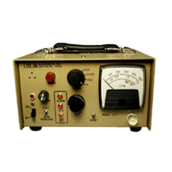
- Page 1 LUDLUM MODEL 177 ALARM RATEMETER October 2018 Serial Number 322945 and Succeeding Serial Numbers...
- Page 2 LUDLUM MODEL 177 ALARM RATEMETER October 2018 Serial Number 322945 and Succeeding Serial Numbers...
- Page 3 RETURN OF GOODS TO MANUFACTURER If equipment needs to be returned to Ludlum Measurements, Inc. for repair or calibration, please send to the address below. All shipments should include documentation containing return shipping address, customer name, telephone number, description of service requested, and all other necessary information.
-
Page 6: Table Of Contents
Model 177 Technical Manual Table of Contents Introduction Getting Started Unpacking and Repacking Preparing the Instrument for Use Operating the Instrument Specifications Description of Controls and Functions Front Panel Back Panel CAL Control Internal Controls (Overhaul Only) Safety Considerations Environmental Conditions for Normal Use... - Page 7 Low Voltage Battery Charge High Voltage Test Alarm Set Voltage Battery Test Voltage Recycling Parts List Model 177 Alarm Ratemeter 10-1 Main Board, Drawing 347 × 496 10-1 Calibration Board, Drawing 347 × 132 10-4 Wiring Diagram, Drawing 347 × 492...
-
Page 8: Introduction
Section 1 Section Introduction he Ludlum Model 177 Alarm Ratemeter may be used with GM (Geiger-Mueller) or scintillation detectors for contamination monitoring, surveying and area monitoring. The unit provides four ranges (in decades) of the analog meter, enabling measurement from 0 to 500,000 counts per minute (CPM) on the standard meter dial;... -
Page 9: Getting Started
Check individual item serial numbers and ensure calibration certificates match between instruments and detectors (if applicable). The Model 177 serial number is located on the back panel of the instrument. To return an instrument for repair or calibration, provide sufficient packing material to prevent damage during shipment. -
Page 10: Operating The Instrument
Model 177 Technical Manual Section 2 Select the operating voltage. This voltage is set by the manufacturer for the detector shipped with the instrument and recorded on the Certificate of Calibration. For other detector/instrument setups, consult the detector manual or manufacturer. Then adjust the potentiometer accordingly. -
Page 11: Specifications
Model 177 Technical Manual Section 3 Section Specifications 95-250 Vac wall transformer and 6 volt gell-cell (sealed lead-acid) Power: battery; typical battery life of approximately 50 hours in a non-alarming condition with a fully charged battery. internal resettable Fuse: toggle switch control selects FAST (2.2 seconds) or... - Page 12 Model 177 Technical Manual Section 3 adjustable from 0 through 150% of full scale Alarm Range: visual indicator (lamp), audible tone and remote current Alarm Output: sink factory set to latching, non-latching alarm available Alarm Control: through the removal of main board resistor R116...
-
Page 13: Description Of Controls And Functions
Model 177 Technical Manual Section 4 Section Description of Controls and Functions Front Panel provides 9 Vdc through a wall transformer to the Power ON-OFF Switch: instrument and trickle-charges the standby battery. In case of line power failure, the battery automatically comes on-line to power the instrument. -
Page 14: Back Panel
Model 177 Technical Manual Section 4 Series "C" connector (Series BNC and MHV connectors are Connector: also available). The connector is provided on the front of the instrument for connection to a detector. This button, when depressed, provides a rapid means of RESET Button: driving the meter needle to zero. -
Page 15: Cal Control
Model 177 Technical Manual Section 4 instrument common (ground). PIN 3: alarm sink. The open collector of a 2N7002L. Limits PIN 4: sink current to 200 milliamperes with open circuit voltage limited to a range of 0 to +50 volts. Unit conducts when in alarm. -
Page 16: Internal Controls (Overhaul Only)
Model 177 Technical Manual Section 4 Internal Controls (Overhaul Only) The following controls are located internally, on the main circuit board: used to adjust charge voltage to 6.825 volts. BAT C: used to adjust meter test voltage reading to 5.97 volts at the BAT T: line. -
Page 17: Safety Considerations
Cleaning Instructions and Precautions The Model 177 Alarm Ratemeter may be cleaned externally with a damp cloth, using only water as the wetting agent. Do not immerse the instrument in any liquid. Observe the following precautions when cleaning: 1. -
Page 18: Warning Markings And Symbols
Model 177 Technical Manual Section 5 Warning Markings and Symbols Caution! The operator or responsible body is cautioned that the protection provided by the equipment may be impaired if the equipment is used in a manner not specified by Ludlum Measurements, Inc. - Page 19 Doing so may result in the unit falling down and causing personal injury and/or property damage. The Model 177 Alarm Ratemeter is marked with the following symbols: CAUTION (per ISO 3864, No. B.3.1) – designates hazardous live voltage and risk of electric shock.
-
Page 20: Calibration And Maintenance
Adjust until the meter DISCR reaches 75% of the generated incoming count rate. Connect the Model 177 to an external voltmeter. Adjust the rear panel control for a reading of 1000 Vdc on the voltmeter. Depress . On HV TEST the main board, adjust for a meter reading of 1.0 kV. -
Page 21: Establishing An Operating Point
Model 177 Technical Manual Section 6 Establishing an Operating Point The operating point for the instrument and detectors is established by setting the detector voltage and instrument sensitivity ( ). The proper selection of this point is the key to instrument performance. -
Page 22: Maintenance
Recalibration should be accomplished after any maintenance or adjustment has been performed on the instrument. Ludlum Measurements recommends recalibration at intervals no greater than one year. Local regulations may have precedence over this recommendation. -
Page 23: Troubleshooting
Model 177 Technical Manual Section 7 Section Troubleshooting ccasionally, you may encounter problems with your LMI instrument or detector that may be repaired or resolved in the field, saving turn-around time and expense in returning the instrument to us for repair. Toward that end, LMI electronics technicians offer the following tips for troubleshooting the most common problems. -
Page 24: Troubleshooting Gm Detectors
Model 177 Technical Manual Section 7 SYMPTOM POSSIBLE SOLUTION Non-linear Readings Check the high voltage (HV) by pressing the button. If a HV TEST Multimeter is used to check the HV, ensure that one with high impedance is used; as a standard multimeter could be damaged in this process. -
Page 25: Troubleshooting Scintillators
Model 177 Technical Manual Section 7 2. Check the HV. For most GM tubes, the voltage is normally 900 Vdc, or 460-550 Vdc for “peanut” tubes (Ludlum Model 133 series). 3. If the input sensitivity is too low, the user could see some double-pulsing. -
Page 26: Technical Theory Of Operation
Model 177 Technical Manual Section 8 Section Technical Theory of Operation Amplifier Negative detector pulses are coupled through C124 to emitter follower Pin U121. R127 protects the input from inadvertent high-voltage shorts. R129 couples the detector to the high-voltage supply. -
Page 27: Alarm
Model 177 Technical Manual Section 8 discharged by R124. The average voltage on C122 is coupled through , and switch to voltage-follower Pin 5 of U311. Pin 7 of ALARM TEST U311 drives the meter and recorder output. Time Constant The meter time constant is determined by R124 and C122. -
Page 28: High Voltage (Hv)
Model 177 Technical Manual Section 8 For counting, audio pulse width is set by R113/C111 of U011 with one pulse per count. For an alarm condition, Pin 4 U111 is held high through CR112 until alarm is reset. Alarm audio tone is controlled by R117 and C112. -
Page 29: Battery Test Voltage
Model 177 Technical Manual Section 8 Battery Test Voltage Battery test voltage is controlled by R002 through switch, BAT TEST ALARM switch, then voltage follower Pin 5 of U311 to the meter. TEST Page 8-4 October 2018 Ludlum Measurements, Inc. -
Page 30: Recycling
To this end, Ludlum Measurements, Inc. strives to supply the consumer of its goods with information regarding reuse and recycling of the many different types of materials used in its products. With many different agencies –... -
Page 31: Parts List
Technical Manual Section 10 Section Parts List Reference Description Part Number Model 177 Alarm UNIT Completely Assembled Ratemeter Model 177 Alarm Ratemeter 48-1632 Main Board, Drawing BOARD Completely Assembled 347 × 496 Circuit Board 5347-502 CAPACITORS C001 10µF, 25V, 04-5655... - Page 32 Model 177 Technical Manual Section 10 Reference Description Part Number C401-C402 1µF, 35V 04-5656 C403 0.1µF, 50V 04-5663 C411 47µF, 10V 04-5666 C421-C423 0.0047UF, 3KV 04-5547 TRANSISTORS Q101 2N7002LT1G 05-5840 Q102 MMBT3904T1G 05-5841 Q103 MJD210 05-5843 Q104 MMBT3904T1G 05-5841 Q111...
- Page 33 Model 177 Technical Manual Section 10 Reference Description Part Number RESISTORS R003 475K, 1%, 250mW 12-7859 R004 150 ohm, 1%, 250mW 12-7062 R011 4.75K, 1%, 250mW 12-7858 R012 82.5K, 1%, 250mW 12-7849 R014-R015 100K, 1%, 250mW 12 7834 R016 100 ohm, 1%, 250mW...
-
Page 34: Calibration Board, Drawing 347 × 132
Model 177 Technical Manual Section 10 Reference Description Part Number R302 1.00K, 1%, 250mW 12-7832 R303 2.21K, 1%, 250mW 12-7835 R311 750K, 1%, 250mW 12-7882 R312 301 ohm, 1%, 250mW 12-7863 R313 475 ohm, 1%, 250mW 12-7851 R315 22.1K, 1%, 250mW... -
Page 35: Wiring Diagram, Drawing 347 × 492
Model 177 Technical Manual Section 10 Reference Description Part Number RESISTOR 680, 1/3W 12-7885 RESISTOR NETWORK 12-7720 MISCELLANEOUS CONN 1-640457-1 MTA100 13 8397 Wiring Diagram, Drawing 347 × 492 46206-LR SLIDE 08-6523 PA-1002 08-6543 SWITCHES 7101-SYZ-QE 08-6511 HV (#923 SWITCHCRAFT) - Page 36 UNIMORPH (TEC3526PU) 21-9251 BATTERY 6V (PS610 GELL CELL) 21-9385 MISCELLANEOUS 1 AMP (FUSE #312001 AGC-1) 21-9704 LAMP-PT 502-OUR-002F-W6 21-9169 LAMP-PT 502-OUR-002F-W6 21-9169 Model 177 METER 4173-166 KNOB PKG-50B 08-6601 KNOB-407D2KI 08-6604 KNOB-LOCK KL 701 08-6607 KNOB-70-1-2G 08-6637 WALL TRANSFORMER 21-8887 PX9025AWPL05 9 VDC 2.5A...
- Page 37 Model 177 Technical Manual Section 11 Section Drawings MAIN BOARD, Drawing 347 × 496 (4 sheets) MAIN BOARD Component Layout, Drawing 347 × 503 CALIBRATION BOARD, Drawing 347 × 132 CALIBRATION BOARD Component Layout, Drawing 347 × 133 CONNECTOR BOARD, Drawing 347 x 489 CONNECTOR BOARD Component Layout, Drawing 347 x 490 WIRING DIAGRAM, Drawing 347 ×...
Need help?
Do you have a question about the 177 and is the answer not in the manual?
Questions and answers