
Related Manuals for Ludlum Measurements 18


Summary of Contents for Ludlum Measurements 18
- Page 1 LUDLUM MODEL 18 ANALYZER March 2012 Serial Number 217996 and Succeeding Serial Numbers...
- Page 2 LUDLUM MODEL 18 ANALYZER March 2012 Serial Number 217996 and Succeeding Serial Numbers...
- Page 3 RETURN OF GOODS TO MANUFACTURER If equipment needs to be returned to Ludlum Measurements, Inc. for repair or calibration, please send to the address below. All shipments should include documentation containing return shipping address, customer name, telephone number, description of service requested, and all other necessary information.
-
Page 5: Table Of Contents
Cleaning and Maintenance Precautions Calibration and Maintenance Establishing an Operating Point Calibration GM Detectors Proportional Detectors Scintillation Detectors Window Calibration HV Calibration Ratemeter Calibration Detector Overload (Option) Calibration With Scintillation Detectors With GM Detectors Maintenance Recalibration March 2012 Ludlum Measurements, Inc. - Page 6 Model 18 Analyzer Technical Manual Batteries Troubleshooting Troubleshooting Electronics which utilize a GM, Scintillator, or Proportional Detector Troubleshooting GM Detectors Troubleshooting Scintillators Troubleshooting Proportional Detectors Recycling Parts List Model 18 Analyzer Main Board, Drawing 363 × 509 Calibration Board, Drawing 363 × 513 Wiring Diagram, Drawing 363 ×...
-
Page 7: Introduction
The Model 18 also incorporates a window circuit allowing a narrow peak to be monitored. For example, by setting the window at 1.5 times threshold, settings of 12 keV through 18 keV for plutonium, 45 keV through 67 keV for americium, and 130 keV through 195 keV for U may be used for a better estimate. -
Page 8: Getting Started
The Model 18 serial number is located on the front panel below the battery compartment. Most Ludlum Measurements, Inc. detectors have a label on the base or body of the detector for model and serial number identification. -
Page 9: Connecting A Detector To The Instrument
A mild electric shock may occur if you make contact with the center pin of the input connector. Switch the Model 18 range selector switch to the position before connecting or disconnecting the cable or detector. -
Page 10: Operational Check
Model 18 Analyzer Technical Manual Section 2 The instrument speaker should emit ˝clicks˝ relative to the rate of counts detected. The switch will silence the audible clicks if in the AUD ON position. It is recommended that the switch be kept in the AUD ON position when not needed in order to preserve battery life. - Page 11 Model 18 Analyzer Technical Manual Section 2 A reference reading with a check source should be obtained at the time of initial calibration or as soon as possible for use in confirming proper instrument operation. In each case, ensure a proper reading on each scale. If the instrument fails to read within 20% of a proper reading, it should be sent to a calibration facility for recalibration.
-
Page 12: Specifications
Model 18 Analyzer Technical Manual Section 3 Section Specifications : GM, proportional, and scintillation Compatible Detectors : ×1, ×10, ×100, and ×1000 selected by a front-panel range Multipliers selector switch : three independent settings adjustable from 400 to 2500 High Voltage volts;... - Page 13 Model 18 Analyzer Technical Manual Section 3 : built-in unimorph speaker with switch (greater than Audio 60 dB at 0.61 m {2 ft}) : toggle switch for 4 seconds in the fast ( ) position or 22 Response seconds in the slow ( ) position from 10% to 90% of final reading : Series ˝C˝...
-
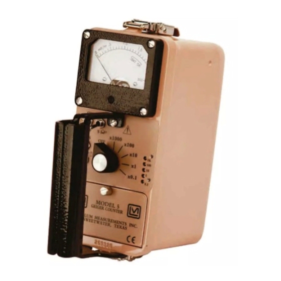
Page 14: Identification Of Controls And Functions
Model 18 Analyzer Technical Manual Section 4 Section Identification of Controls and Functions : A six-position switch marked Range Selector Switch ×1000, ×100, ×10, and ×1. Turning the range selector switch from provides the operator with a battery check of the instrument. A check scale on the meter provides a visual means of checking the battery-charge status. - Page 15 Model 18 Analyzer Technical Manual Section 4 : A three-position switch located below the HV selector switch switch, used for the selection of any one of the desired preset high voltage settings. : Recessed potentiometers located under the calibration HV Adjustments...
-
Page 16: Safety Considerations
Ludlum Measurements, Inc. The Model 18 Analyzer is marked with the following symbols: CAUTION, RISK OF ELECTRIC SHOCK (per ISO 3864, No. B.3.6) –... -
Page 17: Cleaning And Maintenance Precautions
See section 8, “Recycling,” for further information. Cleaning and Maintenance Precautions The Model 18 may be cleaned externally with a damp cloth, using only water as the wetting agent. Do not immerse the instrument in any liquid. Observe... -
Page 18: Calibration And Maintenance
Model 18 Analyzer Technical Manual Section 6 Section Calibration and Maintenance Establishing an Operating Point The operating point for the instrument and probes is established by setting the probe voltage and instrument sensitivity ( ). The proper selection of this point is the key to instrument performance. -
Page 19: Gm Detectors
Model 18 Analyzer Technical Manual Section 6 GM D ETECTORS Note: The GM detector pulse is NOT proportional to Gamma Energy. operation has no function. WINDOW 1. Check GM detector specifications for proper operating high voltage. Select this voltage with the calibration control. -
Page 20: Window Calibration
INDOW ALIBRATION Window calibration will be valid only with the specific detector to be used with the Model 18. A check source will be required. A Model 500 Pulser will be required if the calibration is shifted to another energy. -
Page 21: Hv Calibration
1000 megohm input resistance. High-voltage readout may be calibrated with an internal control. Remove instrument can. Connect the Model 18 to the Model 500 Pulser. Observe the high-voltage reading on the Model 500. Press the pushbutton. Adjust R423 on the main circuit board for the same reading. -
Page 22: Ratemeter Calibration
Model 18 Analyzer Technical Manual Section 6 ATEMETER ALIBRATION The ratemeter may be calibrated by adjusting calibration controls labeled 1, 10, 100, and 1k. Starting with the 1000 range, apply 400,000 CPM from the Model 500. Adjust for proper reading. Drop pulse rate to 100,000 CPM and confirm reading at 100,000 ±10,000 CPM. -
Page 23: Maintenance
Maintenance Instrument maintenance consists of keeping the instrument clean and periodically checking the batteries and the calibration. The Model 18 instrument may be cleaned with a damp cloth (using only water as the wetting agent). Do not immerse instrument in any liquid. Observe the following precautions when cleaning: 1. -
Page 24: Recalibration
Check the appropriate regulations to determine required recalibration intervals. Ludlum Measurements offers a full-service repair and calibration department. We not only repair and calibrate our own instruments, but most other manufacturers’ instruments as well. Calibration procedures are available upon request for customers who choose to calibrate their own instruments. -
Page 25: Troubleshooting
Model 18 Analyzer Technical Manual Section 7 Section Troubleshooting ccasionally, you may encounter problems with your LMI instrument or detector that may be repaired or resolved in the field, saving turnaround time and expense in returning the instrument to us for repair. Toward that end, LMI electronics technicians offer the following tips for troubleshooting the most common problems. - Page 26 Model 18 Analyzer Technical Manual Section 7 SYMPTOM POSSIBLE SOLUTION No power (or meter Check battery contacts. Clean them does not reach with rough sandpaper or use an engraver to clean the tips. TEST BAT OK mark) (continued) Check for loose or broken wires, especially between the main board and the calibration board.
-
Page 27: Troubleshooting Gm Detectors
Model 18 Analyzer Technical Manual Section 7 SYMPTOM POSSIBLE SOLUTION Meter goes full-scale Check for loose wires, especially or “pegs out” between the main board and the (continued) calibration board. Ensure that the instrument’s ˝can˝ is properly attached. When attached properly, the speaker will be located on the left side of the instrument. -
Page 28: Troubleshooting Scintillators
Model 18 Analyzer Technical Manual Section 7 3. If the input sensitivity is too low, the user could see some double-pulsing. 4. Wires to the tube may be broken or the crimped connector could have a loose wire. Troubleshooting Scintillators 1. - Page 29 Model 18 Analyzer Technical Manual Section 7 Neutron He detectors typically require a 2 mV threshold and about 1700 Vdc. Neutron BF detectors typically operate at 1750 Vdc and 30 mV threshold. 3. Gas proportional detectors need P-10 gas, so check the window for tears or leaks and ensure an adequate supply of gas.
-
Page 30: Recycling
To this end, Ludlum Measurements, Inc. strives to supply the consumer of its goods with information regarding reuse and recycling of the many different types of materials used in its products. With many different agencies –... -
Page 31: Parts List
Model 18 Analyzer Technical Manual Section 9 Section Parts List Reference Description Part Number Model 18 Analyzer UNIT Completely Assembled Model 18 Analyzer 48-1613 Main Board, BOARD Completely Assembled Drawing 363 × 509 Main Circuit Board 5363-655 CAPACITORS C001-C002 0.0047μF, 3kV... - Page 32 Model 18 Analyzer Technical Manual Section 9 Reference Description Part Number TRANSISTORS Q021 MJD210 05-5843 Q111 MMBT3904T 05-5841 Q121 MMBT4403LT 05-5842 Q211 MMBT3904T 05-5841 Q301 MMBT3904T 05-5841 INTEGRATED CIRCUITS U021 MAX631AESA 06-6285 U111 TLC27M7ID 06-6292 U211 ICM7555CBA 06-6300 U311-U312 CD74HC4538M...
-
Page 33: Calibration Board, Drawing 363 × 513
Model 18 Analyzer Technical Manual Section 9 Reference Description Part Number R306 4.75k, 1% 12-7858 R307 10k, 1% 12-7839 R308 8.25k, 1% 12-7838 R309 82.5k, 1% 12-7849 R311-R313 100k, 1% 12-7834 R321 10k, 1% 12-7839 R401 1k, 1% 12-7832 R402... -
Page 34: Wiring Diagram, Drawing 363 × 515
Model 18 Analyzer Technical Manual Section 9 Reference Description Part Number 1 M, ×1 09-6814 250k, HV 1 09-6819 250k, HV2 09-6819 250k, HV 3 09-6819 250k, THRESHOLD 09-6819 250k, WINDOW 09-6819 680k, 5% 12-7694 RESISTORS 3.3k 10-7013 RESISTOR NETWORK... - Page 35 Model 18 Analyzer Technical Manual Section 9 Reference Description Part Number PORTABLE KNOB 08-6613 PORT MTR. BEZEL W/MVMNT ASSY. 4363-188 PORT MTR BEZEL W/ GLASS; SCREWS 4363-352 PORT CAL COVER W/SCREWS 9363-200-01 UNIMORPH W/WIRES & O'RING 40-0034 PORT HANDLE (GRIP)
- Page 36 Model 18 Analyzer Technical Manual Section 10 Section Drawings MAIN CIRCUIT BOARD SCHEMATIC, Drawing 363 × 509 MAIN CIRCUIT BOARD LAYOUT, Drawing 363 × 510 CALIBRATION BOARD SCHEMATIC, Drawing 363 × 513 CALIBRATION BOARD LAYOUT, Drawing 363 × 514 WIRING DIAGRAM, Drawing 363 × 516...
Need help?
Do you have a question about the 18 and is the answer not in the manual?
Questions and answers