
Related Manuals for Ludlum Measurements 12


Summary of Contents for Ludlum Measurements 12
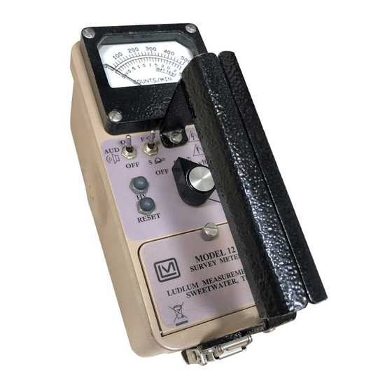
- Page 1 LUDLUM MODEL 12 SURVEY METER July 2017 Serial Number 218039 and Succeeding Serial Numbers...
- Page 2 LUDLUM MODEL 12 SURVEY METER July 2017 Serial Number 218039 and Succeeding Serial Numbers...
- Page 3 RETURN OF GOODS TO MANUFACTURER If equipment needs to be returned to Ludlum Measurements, Inc. for repair or calibration, please send to the address below. All shipments should include documentation containing return shipping address, customer name, telephone number, description of service requested, and all other necessary information.
-
Page 4: Table Of Contents
Cleaning and Maintenance Precautions Calibration and Maintenance Calibration True Reading Calibration Internal Calibration after overhaul Establishing an Operating Point Maintenance Recalibration Batteries Troubleshooting Troubleshooting Electronics which utilize a GM, Scintillator, or Proportional Detector Troubleshooting GM Detectors Ludlum Measurements, Inc. July 2017... - Page 5 HV Power Supply Board (Drawing 464 × 243) Switching Convertor Feedback Voltage Control Filtering Recycling Parts List Model 12 Survey Meter 10-1 Main Board, Drawing 464 × 275 10-1 HV Power Supply Board, Drawing 464 × 243 10-4 Wiring Diagram, Drawing 464 × 309...
-
Page 6: Introduction
Model 12 Technical Manual Section 1 Section Introduction he Model 12 is a portable survey meter with four linear ranges used in combination with exposure rate or meter dials. The instrument features a regulated high-voltage power supply, unimorph speaker with audio... -
Page 7: Getting Started
The Model 12 serial number is located on the front panel below the battery compartment. Most Ludlum Measurements, Inc. detectors have a label on the base or body of the detector for model and serial number identification. -
Page 8: Connecting A Detector To The Instrument
A mild electric shock may occur if you make contact with the center pin of the input connector. Switch the Model 12 range selector switch to the position before connecting or disconnecting the cable or detector. -
Page 9: Reading The Meter Face Dial
Model 12 Technical Manual Section 2 the audible clicks if in the position. It is recommended that the switch be kept in the position when not needed in order to preserve battery life. The detector cable can be a source of problems. Test the detector cable by bending and flexing either end of the cable and checking for an increase in the rate of counts detected. - Page 10 Model 12 Technical Manual Section 2 The same needle indications on successive ranges would be: ×1 = 3.5 kcpm (or 3500 cpm) ×10 = 35 kcpm (or 35,000 cpm) ×100 = 350 kcpm (or 350,000 cpm) A typical dual scale (two arcs) meter face is shown below. The top scale reads 0-2 mR/hr.
- Page 11 Model 12 Technical Manual Section 2 The dial shown below has three arcs: a counts per minute scale (cpm), a linear mR/hr scale, and a non-linear mR/hr scale for the ×100 range only. The meter face also has a position.
-
Page 12: Operational Check
Model 12 Technical Manual Section 2 The same needle indications on successive ranges would be: ×1 = 4.2 kcpm (or 4,200 cpm) ×10 = 42 kcpm (or 42,000 cpm) ×100 = 420 kcpm (or 420,000 cpm) If you use the mR/hr scales, then the readings would be: ×0.1 = 0.13 mR/hr... -
Page 13: Specifications
Model 12 Technical Manual Section 3 Section Specifications : ×1, ×10, ×100, and ×1000 selected by a front-panel range Multipliers selector switch High Voltage : adjustable from 400 to 2500 volts; can be read on the meter; electronically regulated to 1%; support of scintillation loads to... - Page 14 Model 12 Technical Manual Section 3 : two ˝ ˝ cell batteries housed in a sealed externally accessible Power compartment : instrument calibration change less than 3% Battery Dependence within battery check limits on the meter : typically 2000 hours with alkaline batteries (battery...
-
Page 15: Identification Of Controls And Functions
Technical Manual Section 4 Section Identification of Controls and Functions See the Model 12 front-panel drawing at the beginning of this manual to reference the following controls: : 6.4 cm (2.5 in.) arc, 1 mA analog type with pivot-and-jewel (A) Meter suspension. - Page 16 Model 12 Technical Manual Section 4 : when depressed, this switch provides a (F) RES Pushbutton Switch rapid means of driving the meter needle to zero. : In the position, this operates the (G) AUD ON-OFF Toggle Switch unimorph speaker, located on the left side of the instrument. The frequency of the clicks is relative to the rate of the incoming pulses.
-
Page 17: Safety Considerations
Model 12 Technical Manual Section 5 Section Safety Considerations Environmental Conditions for Normal Use The detector may be affected by altitude. Refer to the detector manual for more information. Indoor or outdoor use No maximum altitude Temperature range of -20 to 50 °C (-4 to 122 °F); may be certified for operation from -40 to 65 °C (-40 to 150 °F) -
Page 18: Cleaning And Maintenance Precautions
European Union. It is located on the battery lid. Cleaning and Maintenance Precautions The Model 12 may be cleaned externally with a damp cloth, using only water as the wetting agent. Do not immerse the instrument in any liquid. Observe... -
Page 19: Calibration And Maintenance
Model 12 Technical Manual Section 6 Section Calibration and Maintenance Calibration Calibration controls are located on the front of the instrument under the calibration cover. The controls may be adjusted with a 1/8-inch blade screwdriver. Note: Local procedures may supersede the following The instrument may be calibrated to true reading or, when used with a single source, geometry calibration may be used. -
Page 20: Internal Calibration After Overhaul
Connect instrument to a Model 500 Pulser. Adjust the front-panel adjustment for a pulser high-voltage meter reading of 1500 volts. Depress pushbutton while adjusting the main board potentiometer HV SET (R38) for a Model 12 meter reading of 1500 volts. Ludlum Measurements, Inc. Page 6-2 July 2017... -
Page 21: Establishing An Operating Point
Model 12 Technical Manual Section 6 Establishing an Operating Point The operating point for the instrument and probes is established by setting the probe voltage and instrument sensitivity ( ). The proper selection of this point is the key to instrument performance. Efficiency, background sensitivity and noise are fixed by the physical makeup of the given detector and rarely vary from unit to unit. -
Page 22: Maintenance
Maintenance Instrument maintenance consists of keeping the instrument clean and periodically checking the batteries and the calibration. The Model 12 instrument may be cleaned with a damp cloth (using only water as the wetting agent). Do not immerse instrument in any liquid. Observe the following precautions when cleaning: 1. -
Page 23: Recalibration
Check the appropriate regulations to determine required recalibration intervals. Ludlum Measurements offers a full-service repair and calibration department. We not only repair and calibrate our own instruments, but most other manufacturers’ instruments as well. Calibration procedures are available upon request for customers who choose to calibrate their own instruments. -
Page 24: Troubleshooting
Model 12 Technical Manual Section 7 Section Troubleshooting ccasionally you may encounter problems with your LMI instrument or detector that may be repaired or resolved in the field, saving turn-around time and expense in returning the instrument to us for repair. Toward that end, LMI electronics technicians offer the following tips for troubleshooting the most common problems. - Page 25 Model 12 Technical Manual Section 7 SYMPTOM POSSIBLE SOLUTION No power (or meter Check battery contacts. Clean them does not reach with rough sandpaper or use an engraver to clean the tips. TEST BAT OK mark) (continued) Check for loose or broken wires, especially between the main board and the calibration board.
-
Page 26: Troubleshooting Gm Detectors
Model 12 Technical Manual Section 7 SYMPTOM POSSIBLE SOLUTION Meter goes full-scale Check for loose wires, especially or “pegs out” between the main board and the (continued) calibration board. Ensure that the instrument’s ˝can˝ is properly attached. When attached properly, the speaker will be located on the left side of the instrument. -
Page 27: Troubleshooting Scintillators
Model 12 Technical Manual Section 7 3. If the input sensitivity is too low, the user could see some double-pulsing. 4. Wires to the tube may be broken or the crimped connector could have a loose wire. Troubleshooting Scintillators 1. Alpha or alpha/beta scintillators are prone to light leaks. They can be tested for this problem in a dark room or with a bright light. - Page 28 Model 12 Technical Manual Section 7 2. Neutron He detectors typically require a -2 mV threshold and about 1700 Vdc. Neutron BF detectors typically operate at 1750 Vdc and -30 mV threshold. 3. Gas proportional detectors need P-10 gas, so check the window for tears or leaks and ensure an adequate supply of gas.
-
Page 29: Technical Theory Of Operation
15 millivolts causes the output of U8 to go low. This negative pulse is coupled to pin 5 of U9A for meter drive and pin 12 of U9B for audio drive. The pulse is also available at pin 3 of P2 for special applications. -
Page 30: Scale Ranging
Model 12 Technical Manual Section 8 Scale Ranging Detector pulses from the discriminator are coupled to univibrator pin 5 of U9A. For each scale, the pulse width of pin 6 of U9A is increased by a factor of 10 with the actual pulse width being controlled by the front-panel calibration controls and their related capacitors. -
Page 31: Switching Convertor
Model 12 Technical Manual Section 8 HV Supply Board (Drawing 464 × 243 in back of manual) Switching Convertor High voltage is developed by voltage multiplier CR1 through CR10 and associated capacitors. This multiplier is driven by switching convertor U2 and T1. -
Page 32: Recycling
To this end, Ludlum Measurements, Inc. strives to supply the consumer of its goods with information regarding reuse and recycling of the many different types of materials used in its products. With many different agencies –... -
Page 33: Parts List
Technical Manual Section 10 Section Parts List Reference Description Part Number Model 12 UNIT Completely Assembled Survey Meter Model 12 Survey Meter 48-1609 Main Board, BOARD Completely Assembled Drawing 464 × 275 Main Circuit Board 5464-275 CAPACITORS 47pF, 100V 04-5660 0.1F, 35V-T... - Page 34 Model 12 Technical Manual Section 10 Reference Description Part Number TRANSISTORS MMBT3904LT1 05-5841 MMBT4403LT1 05-5842 Q3-Q4 MMBT3904LT1 05-5841 VOLTAGE REGULATOR LT1460KC53-2.5 05-5867 TPS76038 05-5912 INTEGRATED CIRCUITS U1-U3 MAX4542ESA 06-6453 U4-U5 CMXT3904 05-5888 CMXT3906 05-5890 MAX4541ESA 06-6452 MAX985EUK-T 06-6459 CD74HC4538M 06-6297...
- Page 35 Model 12 Technical Manual Section 10 Reference Description Part Number RESISTORS R1-R5 200K, 1/8W, 1% 12-7992 8.25K, 1/8W, 1% 12-7838 10K, 1/8W, 1% 12-7839 2.37K, 1/8W, 1% 12-7861 R9-R11 10K, 1/8W, 1% 12-7839 1K, 1/4W, 1% 12-7832 10K, 1/8W, 1% 12-7839 4.75K, 1/8W, 1%...
- Page 36 Model 12 Technical Manual Section 10 Reference Description Part Number 640456-4 - MTA100 13-8088 DET PAD-RD120 7464-270 HV PAD-RD120 7464-270 INDUCTORS 22 µH 21-9808 HV Power Supply BOARD Completely Assembled Board, Drawing 464 × 243 HV Power Supply Board 5464-243 C1-C2 0.01F, 3KV, 2%...
- Page 37 Model 12 Technical Manual Section 10 Reference Description Part Number Wiring Diagram, MTA100×5, MAIN BOARD Drawing 464 × 309 5464-275 13-8140 CONNECTORS MTA100×6, OPTIONAL 5464-275 13-8095 MTA 100×2, MAIN BOARD 5464-275 13-8073 MTA100×4, MAIN BOARD 5464-275 13-8088 MAIN BOARD 5464-275...
-
Page 38: Hv Power Supply Board, Drawing 464 × 243
Model 12 Technical Manual Section 11 Section Drawings MAIN CIRCUIT BOARD, Drawing 464 × 275 (3 sheets) MAIN CIRCUIT BOARD LAYOUT, Drawing 464 × 276 (2 sheets) HV POWER SUPPLY BOARD, Drawing 464 × 243 HV POWER SUPPLY BOARD LAYOUT, Drawing 464 × 244 WIRING DIAGRAM, Drawing 464 ×...
Need help?
Do you have a question about the 12 and is the answer not in the manual?
Questions and answers